Table of Contents
Advertisement
Advertisement
Table of Contents

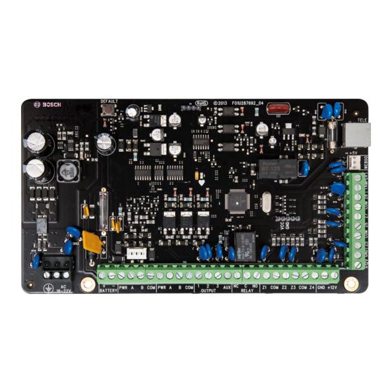
Summary of Contents for Bosch ICP-SOL2-P
- Page 1 Control Panel ICP-SOL2-P/ICP-SOL3-P Installation Guide...
-
Page 3: Table Of Contents
Control Panel Table of Contents | en Table of contents Introduction About documentation Related documentation Bosch Security Systems, Inc. product manufacturing dates System Overview ICP-SOL2-P ICP-SOL3-P Configuration and Parts 2.3.1 Control panel capacities 2.3.2 Parts list 2.3.3 Order separately Installation workflow... - Page 4 en | Table of Contents Control Panel Disable Factory Defaults Configuring for email System Operations Arming the system in AWAY Mode Disarming the system from AWAY Mode Arming the System in STAY Mode 1 Disarming the system from STAY Mode 1 Arming the system from STAY Mode 2 Disarming the system from STAY Mode 2 Codepad duress alarm...
- Page 5 Control Panel Table of Contents | en 7.4.8 Fault Analysis Mode 7.4.9 Initiate a Modem Call 7.4.10 Reset Latching Outputs 7.4.11 Change the Codepad Buzzer Tone 7.4.12 Send Test Report Domestic Dialing Domestic Dialing Funtion Setting Up and Programming Domestic Reporting Zone Information Day Alarm Information 9.1.1...
- Page 6 en | Table of Contents Control Panel 11.3 System Options 3 11.4 System Options 4 11.5 Consumer Options 1 11.6 Consumer Options 2 11.7 Consumer Options 3 Partitioning 12.1 Programming 12.1.1 Partitioning Options 1 12.1.2 Partitioning Options 2 12.2 Zone allocations 12.2.1 Zone area assignments 12.2.2...
- Page 7 Control Panel Table of Contents | en 17.9 RF Low Battery Report 17.10 Arm/Disarm Reports 17.11 Codepad Duress Report 17.12 Codepad Panic Report 17.13 Codepad Fire Report 17.14 Codepad Medical Report 17.15 AUX Power Supply Fail Report 17.16 AUX Power Supply Fail Restore Report 17.17 AC Fail Report 17.18...
-
Page 8: Introduction
These indicate a hazardous situation which, if not avoided, could result in death or serious injury. Copyright This document is the intellectual property of Bosch Security Systems, Inc. and is protected by copyright. All rights reserved. Trademarks All hardware and software product names used in this document are likely to be registered trademarks and must be treated accordingly. -
Page 9: Bosch Security Systems, Inc. Product Manufacturing Dates
*Shipped with the product. Bosch Security Systems, Inc. product manufacturing dates Use the serial number located on the product label and refer to the Bosch Security Systems, Inc. website at http://www.boschsecurity.com/datecodes/. The following image shows an example of a product label and highlights where to find the manufacturing date within the serial number. -
Page 10: System Overview
| System Overview Control Panel System Overview ICP-SOL2-P Callout - Description 1 – Control panel 2 – Keyfob 3 – WE800EV2 receiver 4 – IUI-SOL adapter 5 – Domestic call 6 – CMS A-Link Plus 7 – PSTN 8 - Receiver 9 –... - Page 11 Control Panel System Overview | en Callout - Description 10 - Email 11 – B426 12 – Smartphone app 13 – Wired detector 14 – Touchscreen codepad 15 – LCD text codepad 16 – LCD icon codepad 17 – B308 18 –...
-
Page 12: Icp-Sol3-P
en | System Overview Control Panel ICP-SOL3-P Callout - Description 1 – Control panel 2 – Wireless detector 3 – Wireless repeater 4 – Wireless keyfob 5 – Wireless receiver 6 – Keyfob 7 – WE800EV2 receiver 8 – IUI-SOL adapter 9 –... -
Page 13: Configuration And Parts
2 way communication Direct link Configuration and Parts This section lists each control panel's capacities and a parts list. 2.3.1 Control panel capacities Features ICP-SOL2-P ICP-SOL3-P Number of users Number of zones 4+4 (ZD) 8+8 (ZD) Number of areas/partitions Number of on-board outputs... -
Page 14: Parts List
Number of RADION receivers Number of RADION repeaters 2.3.2 Parts list Control panels ship assembled from the factory with the following parts: Literature – Control Panels (ICP-SOL2-P/ICP-SOL3-P) Quick Reference Guide – Control Panels (ICP-SOL2-P/ICP-SOL3-P) User Guide HW pack – EOL resistors –... -
Page 15: Installation Workflow
Before installing and operating the control panel, read these instructions. Failure to follow these procedures may cause the device not to function properly. Bosch Security Systems Inc. is not responsible for any devices that are improperly installed, tested, or maintained. -
Page 16: Accessories
| Accessories Control Panel Accessories Bosch Security Systems, Inc. manufactures a number of accessories that can be used in conjunction with the control panel. These devices enhance certain features to make the system extremely flexible. Some sections include basic installation instructions. For detailed installation instructions, refer to the Installation Guide that came packaged with the device. - Page 17 Control Panel Accessories | en The IUI-SOL-TEXT and IUI-SOL-ICON have 6 DIP switches that support SDI2 addresses 01 to 16. DIP switches determine the address for the codepad. The control panel uses the address for communications. Use a ballpoint pen to set the switches. If multiple codepads reside on the same system, each codepad must have a unique address.
-
Page 18: Icon Codepad Indicators
en | Accessories Control Panel Callout - Description 1 – Control panel 2 – Terminal wiring 3 – Codepad’s wiring terminal block 4.1.1 Icon Codepad Indicators Codepad indicator Status Definition icons Zone is unsealed. Zone is sealed. ZONE 1 – 8 for ICP- Flashing Fast (0.25 sec Zone is in alarm condition. -
Page 19: Text Codepad Indicators
Control Panel Accessories | en Codepad indicator Status Definition icons Flashing These two indicators flash when you enter Installer’s Programming Mode or use any Master Code function. Programming Mode The OFF indicator lights when the system is disarmed and flashes when a zone becomes unsealed when disarmed. - Page 20 en | Accessories Control Panel Codepad key Function Switch the display item on codepad idle display except the master codepad. Page down the fault item and recall event. Turn menu/option item up. Entry program menu ([-] or PIN+[-]). Exit program item setting. Return to the upper level menu.


Need help?
Do you have a question about the ICP-SOL2-P and is the answer not in the manual?
Questions and answers