
Related Manuals for Fagor Innova 40i TS


Summary of Contents for Fagor Innova 40i TS
- Page 1 Innova 40i TS / 40i TS-B Installation / Oper ation Manual Manual code: 14460114 Manual ver sion: 1205 Software ver sion: 2.00...
-
Page 2: Table Of Contents
INDEX DRO description ..................3 Front plate: ........................3 Turning the unit on and off ..................... 3 Main screen description: ....................4 Function bar ........................4 1.4.1 Access to functions: .........................4 DRO operation ................... 5 Display modes......................... 5 2.1.1 mm / inch ............................5 2.1.2 rad/diam ............................5... - Page 3 Warranty terms ..........................28 4.2.4 Material returning terms .........................28 IMPORTANT NOTE Some of the features described in this manual may not be available in this version. Consult with the Fagor Automation branch office nearest you. 40i TS - v1205 - Installation/Operation - (2/29)
-
Page 4: Dro Description
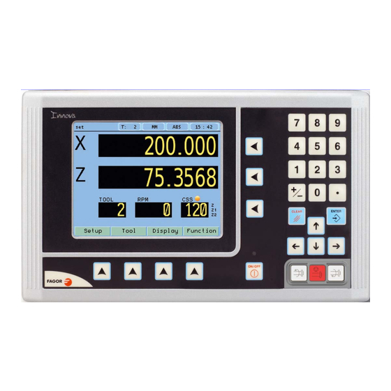
1 DRO description 1.1 Front plate: Keys for axes Keys for entering numeric values TFT screen Abort Validate Cursor keys Spindle keys Keys to open droplist buttons of the FUNCTION BAR Power-off button Power indicator LED 1.2 Turning the unit on and off It turns on automatically when applying voltage or after pressing the on/off key. -
Page 5: Main Screen Description
1.3 Main screen description: Display mode: Display units mm/inch INC/ABS Spindle orientation Chronometer Set/Clear Active tool Nr. STATUS BAR DISPLAY AREA Current range FUNCTION BAR Current tool Current/programmed RPM Current/programmed CSS CSS mode ON When the spindle is off, the RPM and CSS displays show the programmed values. When the spindle is ON and there is an encoder on the spindle, the RPM and CSS displays will show the current value;... -
Page 6: Dro Operation
2 DRO operation Display modes. Toggle the reading of the second axis between Z (Z1 + Z2), Z1 or Z2, when the DRO has been set for 3-axis lathe. 2.1.1 mm / inch Display mm/inch Toggle units between mm and inches. This toggle is possible if the installer parameters have been set as toggle . -
Page 7: Set/Clear
Set/Clear Display Set/Clear There are two ways (modes) to set a value (Set) on the display or zero it (Clear). 2.2.1 In " Set" mode (indicated with an " S" on the upper status bar) Value To preset a value for an axis. To zero the axis, either preset a 0 value using the previous keystroke sequence or use this other sequence (clear + axis). -
Page 8: Tool Setting
2.4.0.1 Tool setting: Teach When going into Teach mode, if the DRO was in INC mode, it switches to ABS mode. 2.4.0.2 Setting the tool by touching a part of known diameter: Enter tool number. Press Enter. Move the X axis until the tool touches the part. Preset the part diameter. -
Page 9: Machine Control
Machine control This unit offers the possibility to control the spindle as well as the inputs and outputs required for it. 2.5.1 Spindle Control The Start Stop keys control the machine spindle. Start spindle in m3. Start spindle in m4. Stop the spindle. -
Page 10: Control Of Maximum Spindle Speed
2.5.3 Control of maximum spindle speed Maximum spindle speed may be limited by an external device connected to inputs DT1, DT2, DT3 and DT4. A rotary selector switch may be used, binary, bcd, gray, etc. Or an intelligent device for safety. -
Page 11: Set Rpm
2.6.1 Set RPM Function For setting the RPM value for the current tool. RPM: Desired value in revolutions per minute Range: Gear range position Validate the programmed values Exit without changing values Note: The preset value must be between the minimum and the maximum rpm for the selected range (gear). Setting the RPM value turns the CSS mode OFF. -
Page 12: Turning Function
2.6.4 Turning function. Function Turning Assistant for defining a turning cycle after having entered the following data: X: Starting diameter. Move the X axis until the tool touches the part. Press X axis button to enter the position value on the X axis. If the part diameter is known, its value may be entered directly. -
Page 13: Dro Installation
3 DRO installation There are two ways to mount the Innova 40i TS: 1- Mounted on the support arm. 2- Built-in model. Mounting on the support arm. The DRO may be mounted at the desired height and may be oriented at will. -
Page 14: Rear Panel
Rear panel On the back of the unit the following items may be found: * Three-prong power connector for AC and ground connection. * M6 mm terminal, for general machine ground connection. * Mounting bracket. * Feedback connectors: X1.-SUB-D HD type 15-pin female connector for 1st axis feedback device. X2.-SUB-D HD type 15-pin female connector for 2nd axis feedback device. -
Page 15: General Technical Characteristics
General technical characteristics Universal Power Supply between 100V AC and 240V AC ±10% at mains frequency between 45 Hz and 400 Hz between 120V DC and 300 V DC. It withstands power outages of up to 20 milliseconds. -10-year memory backup of installation parameters when the unit is off. -The operating temperature inside the DRO enclosure must be between 5º... -
Page 16: Input/Output Connection 37-Pin Connector
3.5.2 Input/output connection 37-pin connector Characteristics of the analog input: Voltage range: ±10V Impedance > 10 kOhm Maximum unshielded cable length: 75mm Characteristics of the analog output: Voltage range: ±10V Minimum impedance of the input to which it is connected: 10 kOhm Maximum unshielded cable length: 75mm We recommend using shielded cables joining the shield to the connector housing at each end. -
Page 17: Connection Diagram
Out 4 Out n 0V external Out 1 3.5.2.2 Connection example SPINDLE ENCODER MOTOR GEAR CONTROL RANGE CONTROL LIMIT ANALOG. SPINDLE ANALOG. GND INNOVA 40i TS DIGITAL POT. ANALOG. EXTERNAL POTENTIOMETER SWITCH EMERGENCY 40i TS - v1205 - Installation/Operation - (16/29) -
Page 18: Power And Machine Connection
3.5.3 Power and machine connection Always mount it vertically so its keyboard is within operator's reach and its digits are easily visible (at operator's eye level). Do not connect or disconnect the DRO connectors while it is under power. Connect all metallic parts to a common point on the machine tool and it to the general ground point. Use cables of enough gage (no thinner than 8 mm ) for this connection. -
Page 19: Installer Parameters
3.6.2.2 Screen color Use the cursor keys to change the colors for the background, for the numbers, for the box, etc. ColorSet The default box shows the three preset options: 1- Default: Blue background with yellow numbers. 2- Color 1: Black background with yellow numbers. 3- Color 2: Green background, white box and green numbers. - Page 20 Axes option: Setup Setup Axes Installer parameters These parameters must be set for each axis. Note: To select the spindle axis (the 4th axis), press the 3rd axis key twice. 1- Combine axes: It is possible to add/subtract any axis to/from another axis.
-
Page 21: Feedback
1Vpp or TTL with distance-coded reference marks. Example: We wish to install a FAGOR GP linear encoder (1 Vpp and 20-micron-pitch graduated glass) with 1 micron resolution: Graduation pitch (20, 40 or 100 µm) -
Page 22: Compensation
This protocol is configured with the following parameters: * Resolution: Only requested if the axis is linear. The resolution to be used with FAGOR absolute linear encoders is 0.0001 mm. *Number of bits: It sets the digital communication between the encoder and the DRO. -
Page 23: Test Mode
Important Before capturing data for an accuracy graph, a home search must be carried out because the compensation will not be applied until the home search is done. To use this compensation, it is recommended to force a home search on power-up. Pressing the Edit button displays a table with 105 points Edit and their corresponding error values. -
Page 24: Spindle Configuration
3.6.5.1 Spindle Configuration Setup Setup Machine Control Setup Spindle Installer parameters For setting the values for spindle control. Spindle encoder. Defines whether the machine has an encoder connected to the spindle or not. Spindle control: When selecting closed loop, the DRO will try to follow the programmed rpm. -
Page 25: Range Configuration
3.6.5.3 Range configuration Setup Setup Machine Control Range Param. Instal. It sets the values for range control Automatic range (gear) detection: For safety, the DRO will control the current range by reading the digital inputs. External speed box: For safety, an external box or selector that indicates to the DRO the maximum RPM allowed. -
Page 26: Active Level Configuration
3.6.5.6 Active level configuration Setup Setup Machine Control Inputs/Outputs Param. Instal. For setting the active level for the digital inputs. Pressing this key displays the following screen: Setup Setup Machine Control Outputs Param. Instal. For setting the active level for the digital outputs. 3.6.5.7 External device or box for speed limitation Setup... -
Page 27: Appendix
Read the following safety measures in order to prevent damage to personnel, to this product and to those products connected to it. Fagor Automation shall not be held responsible for any physical or material damage derived from the violation of these basic safety regulations. - Page 28 Ground connection In order to avoid electrical discharges, connect the ground terminals of all the modules to the main ground terminal. Before connecting the inputs and outputs of this unit, make sure that all the grounding connections are properly made. Before powering the unit up, make sure that it is connected to ground In order to avoid electrical discharges, make sure that all the grounding connections are properly made.
-
Page 29: Warranty Terms
The cardboard being used to make the box must have a resistance of 170 Kg (375 lb.). When sending it to a Fagor Automation office for repair, attach a label indicating the owner of the unit, person to contact, type of unit, serial number, symptom and a brief description of the problem. - Page 30 20500 Arrasate/Mondragón - Spain - Fagor shall not be held responsible for any printing or transcribing errors in this manual and reserves the right to make any modifications to the characteristics of their products without prior notice. 40i TS - v1205 - Installation/Operation - (29/29)
Need help?
Do you have a question about the Innova 40i TS and is the answer not in the manual?
Questions and answers