Fagor CNC 8070 Operating Manual
Hide thumbs
Also See for CNC 8070:
- Programming manual (556 pages) ,
- Operating manual (414 pages) ,
- Hardware configuration (276 pages)
Table of Contents
Advertisement
Quick Links
Advertisement
Table of Contents

Related Manuals for Fagor CNC 8070


Summary of Contents for Fagor CNC 8070
- Page 1 . 0509) V03.0 OPERATING MANUAL (Soft V03.0x) (Ref. 0509)
- Page 3 Operating manual Unauthorized copying or distributing of this software is prohibited. All rights reserved. No part of this documentation may be transmitted, transcribed, stored in a backup device or translated into another language without Fagor Automation’s consent. ® ® Microsoft and Windows are registered trademarks of Microsoft Corporation, U.S.A.
- Page 5 FAGOR AUTOMATION shall not be held responsible for any personal injuries or physical damage caused or suffered by the CNC resulting from any hardware manipulation by personnel unauthorized by Fagor Automation. If the CNC hardware is modified by personnel unauthorized by Fagor Automation, it will no longer be under warranty. COMPUTER VIRUSES FAGOR AUTOMATION guarantees that the software installed contains no computer viruses.
-
Page 7: Table Of Contents
Operating manual I N D E X CHAPTER 1 GENERAL CONCEPTS CNC configuration. Hardware..................1 Turning the CNC on and off ..................3 1.2.1 Emergency shutdown with battery................. 4 Description of the keys ....................5 1.3.1 Keys associated with the information on the screen ..........5 1.3.2 Keyboard layout ..................... - Page 8 Operating manual Operations with the axes ..................67 4.2.1 Home search ....................... 67 4.2.2 Jogging the axes....................68 4.2.3 Jogging the axes with handwheels ..............70 4.2.4 Moving an axis to a particular position (coordinate) ..........72 4.2.5 Coordinate preset ....................73 Spindle control......................
- Page 9 Operating manual CHAPTER 7 MDI MODE Appearance of the MDI mode................152 7.1.1 Window description.................... 153 Standard MDI window ................... 154 7.2.1 Block editing and execution ................155 Full MDI screen ..................... 156 7.3.1 Block execution ....................158 7.3.2 Save the blocks as a program................159 CHAPTER 8 USER TABLES Appearance of the table mode................
- Page 10 Operating manual 11.4 Program editing (softkeys)..................225 11.4.1 Analyze......................225 11.4.2 File ........................225 11.4.3 Undo ........................226 11.4.4 Operations with blocks..................226 11.4.5 Find/Replace ..................... 227 11.4.6 Customizing....................... 228 11.5 Program monitoring ....................229 11.6 Program monitoring (softkeys) ................230 11.7 "Commands"...
- Page 11 Operating manual 14.7 –Monitoring– service ..................... 308 14.8 –Information– service .................... 309 14.9 Command generator....................311 CHAPTER 15 DIAGNOSIS 15.1 Appearance of the diagnosis mode ............... 314 15.1.1 Screen description ..................... 315 15.1.2 Icon description (vertical softkeys)..............316 15.2 Configuration diagnosis ..................317 15.2.1 System diagnosis....................
- Page 13 Before starting up the CNC, read the instructions of chapter 1 in the Installation Manual. Warning The information described in this manual may be changed due to technical modifications. FAGOR AUTOMATION, S. Coop. reserves the right to make any changes to the contents of this manual without prior notice. CNC 8070 V03.0...
- Page 15 ABOUT THE PRODUCT Software options Bear in mind that some of the features described in this manual depend on the software options that are installed. “GP” model “M” model “T” model Number of execution channels 1 to 4 1 to 4 1 to 4 Number of axes 4 to 28...
- Page 17 VERSION HISTORY Here is a list of the features added in each software version and the manuals that describe them. The version history uses the following abreviations: INST Installation manual Programming manual Operation manual Software V01.01 February of 2002 First version. Software V1.11 September 2002 Feature...
- Page 18 Feature Jog mode. Programming of feedrate “F” and spindle speed “S”. Axis selection/deselection for handwheel jog. Theoretical path simulation. Definition of the first block of a block search. Confirm that the CNC is not in automatic mode when executing a program. Syntax check in MDI.
- Page 19 Feature Electronic-cam editor. INST Optimize the reading and writing of variables from the PLC. Only the following will be INST / PRG asynchronous. • The tool variables will be read asynchronously when the tool is neither the active one nor in the magazine. •...
- Page 20 Software V3.01 July 2005 Feature Lathe model New machine parameters. INST • CAN bus type selection (CANMODE). • permit using the G95 function in jog mode (FPRMAN). • Lathe model. Graphics configuration selection (GRAPHTYPECH). • Lathe model. Axis configuration selection (GEOCONFIG). •...
- Page 21 DECLARATION OF CONFORMITY Manufacturer: Fagor Automation, S. Coop. Barrio de San Andrés 19, C.P. 20500, Mondragón -Guipúzcoa- (SPAIN). We declare: under our responsibility that the product: Fagor CNC8070 Numerical Control meets the following directives: Safety: EN 60204-1 Machine safety. Electrical equipment of the machines.
- Page 23 This unit may only be repaired by authorized personnel at Fagor Automation. Fagor Automation shall not be held responsible of any physical damage or defective unit resulting from not complying with these basic safety regulations.
- Page 24 It is recommended, whenever possible, to install the CNC away from coolants, chemical product, blows, etc. that could damage it. This unit complies with the European directives on electromagnetic compatibility. Nevertheless, it is recommended to keep it away from sources of electromagnetic disturbance such as: •...
- Page 25 PRECAUTIONS DURING REPAIR Do not get into the inside of the unit. Only personnel authorized by Fagor Automation may manipulate the inside of this unit. Do not handle the connectors with the unit connected to AC power. Before manipulating the connectors (inputs/outputs, feedback, etc.) make sure that the unit is not connected to AC power.
- Page 27 Fagor Automation is committed to repairing or replacing their products from the time they launch them up to 8 years after they disappear from the product catalog. It is entirely up to Fagor Automation to determine whether a repair is to be considered under warranty.
- Page 29 MATERIAL RETURNING TERMS When sending the Central Unit or the Remote Modules, pack them in its original package and packaging material. If the original packaging material is not available, pack it as follows: 1. Get a cardboard box whose three inside dimensions are at least 15cm (6 inches) larger than those of the unit.
- Page 31 ADDITIONAL REMARKS Mount the CNC away from coolants, chemical products, blows, etc. which could damage it. Before turning the unit on, verify that the ground connections have been properly made. In order to avoid electrical shock at the Central Unit, use the proper power (mains) cable. Use 3-wire power cables (one for ground connection).
- Page 33 RELATED DOCUMENTATION Manuals directed to the machine manufacturer or to the person in charge of doing the installation and start-up of the CNC. Hardware manual. It describes the hardware configuration and the technical data of each element. Installation Manual. It describes how to install and start up the CNC. Manuals directed to the end user;...
-
Page 35: Cnc Configuration. Hardware
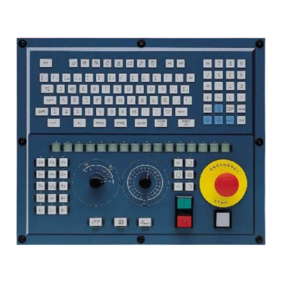
GENERAL CONCEPTS This manual describes how to operate with the CNC using the keyboard, monitor and the operator panel. It also describes the various CNC operating modes as well as how to operate with each of them. CNC configuration. Hardware Monitor, keyboard and operator panel The CNC assembly comprises the monitor, keyboard and the operator panel. - Page 36 Operating manual Network connection (Ethernet) The CNC may be connected to a computer network through specific connectors. The CNC must be configured as any node of the network as if it were a regular PC. The following actions are possible when having a CNC configured as a node within the computer network: •...
-
Page 37: Turning The Cnc On And Off
Operating manual Turning the CNC on and off The way the CNC is turned on and off depends on how it has been set by the machine manufacturer. However, the most common way to do it is as follows. Turning the CNC on After powering up the unit, the operating system (Windows 95 or Windows XP) will start up first. -
Page 38: Emergency Shutdown With Battery
Operating manual 1.2.1 Emergency shutdown with battery The central unit PC104 is powered by an external 24Vdc power supply. Optionally, an external battery may be connected to ensure the detection of power supply voltage drops and that the unit is turned off properly. When a power supply failure occurs (24V voltage drop) and there is a battery connected to the central unit, the latter responds as follows: •... -
Page 39: Description Of The Keys
Operating manual Description of the keys 1.3.1 Keys associated with the information on the screen Softkeys The softkeys or functions keys may be used to select the different options shown on the screen. Horizontal softkeys. It selects the options of the horizontal menu. Vertical softkeys. -
Page 40: Keyboard Layout
Operating manual 1.3.2 Keyboard layout Depending on the utility of the different keys, the CNC keyboard may be considered to be laid out as follows. Work modes To access the different CNC work modes directly. Automatic mode. Jog mode. MDI mode. Editing - simulation mode. - Page 41 Operating manual Alphanumeric keyboard It includes the necessary keys to edit programs as well as the following special keys: Shift key for capital letters. By keeping it pressed and in combination with a another key, it accesses a second set of characters for that other key shown at the top of that key. When combined with a letter, it writes it in capital letters.
-
Page 42: Description Of The Operator Panel
Operating manual 1.3.3 Description of the operator panel Depending on the utility of the different elements, the operator panel may be considered to be laid out as follows: JOG keys They are used to jog the axes. There are two types of JOG panels: There are two keys for each axis. - Page 43 Operating manual Spindle control It is used to govern the spindle. It consists of the following keys. Start the spindle clockwise. To stop the spindle. Start the spindle counterclockwise. To vary the spindle speed percentually. Spindle orientation. Execution keys Cycle start key. It executes the program selected in the execution mode regardless of the active work mode (except for MDI mode).
-
Page 44: Directory Structure
Do not change the contents of this directory. Only authorized personnel from Fagor Automation may modify the contents of this directory. Fagor Automation shall not be held responsible of the performance of this CNC if the contents of this directory have been changed. -
Page 45: Mtb (Machine Tool Builder) Directory
• In the directory "...\MMC\IMAGES", the machine builder may include all the files of the application regarding bitmaps, videos, icons, etc. Initially, it will be a copy of the directory "...\FAGOR\MMC". This directory keeps the information regarding the PLC integrated by the machine builder: •... -
Page 46: Users Directory
Operating manual 1.4.2 USERS directory It is especially directed at users. The purpose of this directory is to provide the user with a memory space for storing part-programs, profiles, etc. as they are generated. Although the user may store these programs in any directory, they should be saved in the directories created for this purpose in order to make it easier and faster to find them and make safety backup copies. -
Page 47: Screen Description
HOW TO OPERATE THE CNC Screen description The CNC screens shows the following information: A. General CNC-status bar. It shows the information on the program being executed, the active operating mode and the PLC messages. See "Detailed description of the CNC status bar"... -
Page 48: Detailed Description Of The Cnc Status Bar
Operating manual 2.1.1 Detailed description of the CNC status bar The top of the screen shows the following information: A. Icon (customizable) identifying the manufacturer. B. Icon showing the status of the program of the active channel: The background color will be different depending on the status of the program. Programmed stopped. - Page 49 Operating manual Channel 1 (CH1) is expecting synchronism marks from the rest of the channels. The marks of channels 2 and 4 are set to 1. The mark of channel 3 is set to zero. Channel 2 is not expecting any synchronism mark. (In the graphic, the white LED's are identified with the letter -W-, the green ones with the letter -G- and the red ones with the letter -R-).
-
Page 50: Operating Modes
Operating manual Operating modes 2.2.1 How to access to the operating modes The CNC operating modes may be accessed from the keyboard or from the task window that is displayed with the key combination [CTRL]+[A]. Each operating mode may consist of several screens or pages. Switching between the different screens is done by pressing the access key for that operating mode. - Page 51 Operating manual Task window All CNC operating modes may be accessed from the task window. Use the [CTRL] + [A] keys to open the task window. Press [ESC] to close the window without making a selection. The task window looks like this. A.
-
Page 52: Description Of The Various Operating Modes
Operating manual 2.2.2 Description of the various operating modes Automatic mode It is used to execute part-programs in automatic or single-block mode. While executing a part-program, any other operating mode may also be accessed (except "MANUAL" and "MDI") without interrupting the execution of the program. This way, a program may be edited while another one is running (background editing). - Page 53 Operating manual It is used to operate with the PLC (edit a program, monitor, change the status of its variables, etc.). Machine parameter table It is used for setting the machine parameters to adapt the CNC to the machine. Tuning mode. Setup assistance For faster and easier machine setup.
-
Page 54: Dialog Boxes
Operating manual Dialog boxes The dialog boxes consist of the following elements. All the actions may be carried out with the mouse or via keyboard. • Selection panels. It selects among the different option groups within the same dialog box. •... -
Page 55: Windows For Warnings And Errors
Refer to the error solving manual for a detailed description of the cause of the error and its possible solutions. FATAL ERROR They are errors that force the operator to turn the CNC off. If the error persists, contact the Service Department at Fagor Automation. CNC 8070 V03.0... -
Page 56: File Selection Window
Operating manual File selection window The file selection window is common to all operating modes. This window is displayed when, from an operating mode, the operator selects the option to open, save or import a file, open or load a table, etc. From this window, it is possible to either select an existing file or create a new one. - Page 57 Operating manual To select a file from the list To make searching easier, the file list may be sorted according to different criteria. "Sorting the list of files" on page 23. A file may be selected from the list: 1. Select the folder that contains the program. 2.
- Page 58 Operating manual File search It is used to look for files whose names contain a particular character string. When selecting this option, the CNC shows a dialog box requesting the text to be found. The programs are searched one by one. It may be searched using either the softkey menu or the following keys.
-
Page 59: Calculator
Operating manual Calculator The calculator may be accessed from any task window or directly using the key combination [CTRL]+[K]. Press [ESC] to close the calculator. The calculator may be accessed from any operating mode. When accessing from an editable element, the result displayed by the calculator may be inserted. An editable element is any element that may have a focus or cursor, such as the program editor, tables, editable data, etc. - Page 60 Operating manual Softkey menu The softkey menu shows all the available operations. The expressions may be edited using either the softkey menu or the mouse with the calculator keys. Work units The result of the operations may be given in various units. Use the following icons to change the units.
-
Page 61: Defining Expressions
Operating manual 2.6.1 Defining expressions An expression may consist of one or more operations. Each one of them may be defined by any valid combination of variables, constants, functions and operations. Press [ENTER] To accept the expression entered and calculate the value. Quick parenthesis insertion To place a portion of an expression between parenthesis, select the portion and press one of the parenthesis keys "("... - Page 62 Operating manual Arithmetic operations. x + y x - y Subtract x *y Multiply x / y Divide x % y Percentage 10%50 = 5 x ^ y Power 2^3 = 2 2 2 = 8 Factor 3! = 3 2 1 = 6 Trigonometric operations.
- Page 63 Operating manual The "E" variables define the error allowed so the result of the function with the calculated value is smaller than "E". This variable is useful when not knowing what value to assign to "N". In that case, it is recommended to assign to "N" a very large value and to "E"...
-
Page 64: Keyboard Shortcuts
Operating manual Keyboard shortcuts Operations at the interface To perform different operations with the CNC. [CTRL] + [W] Minimize/Maximize the CNC. [CTRL] + [J] Show / hide the virtual operator panel. [CTRL] + [M] Show / hide the PLC message list. [CTRL] + [O] Show / hide the CNC message list. - Page 65 Operating manual Program editor Keyboard shortcuts available at the part-program and PLC program editor. [CTRL]+[TAB] Toggle between the editor and the error window. [CTRL]+[C] Copy the selected text onto the clipboard. [CTRL]+[X] Cut the selected text. [CTRL]+[V] Paste the selected text. [CTRL]+[Z] Undo the last change.
- Page 66 Operating manual CNC 8070 V03.0...
- Page 67 AUTOMATIC MODE Automatic mode selection The automatic mode may be selected from any other operating mode by pressing its relevant key. This work mode may be accessed from any channel and even from several channels at the same time. A different program may be executed in each channel. From the automatic mode, and even while a program is in execution, it is possible to access another work mode except the JOG mode and the MDI mode.
-
Page 68: Displaying The Automatic Mode
The standard configuration of this work mode, described in this manual corresponds to the one supplied by Fagor. In some cases, the manual shows a sample screen, instead of that of the CNC in order to make it easier to understand. -
Page 69: Description Of The Screens
Operating manual 3.1.1 Description of the screens As mentioned earlier, the automatic mode may consist of one or several of the following screens (later sections of this chapter describe each one in further detail). Data screen They show execution related data: axis position, "M" and "G" function history, active tool and tool offset, spindle speed and axis feedrate. -
Page 70: Description Of The General Status Bar
Operating manual 3.1.2 Description of the general status bar The general status bar shows the following information associated with the automatic mode: A. Program selected in the active channel for execution. The background color of the window will be different depending on the program status. -
Page 71: Channel Synchronization Window
Operating manual 3.1.3 Channel synchronization window The channel synchronization window is available in all work modes. This window may be expanded using the key combination [ALT]+[S]. The synchronization is carried out using marks in the programs. The window shows for each channel whether it is waiting for synchronization marks or not and the status of those marks in the channel that originates them. -
Page 72: Icon Description (Vertical Softkeys)
Operating manual 3.1.4 Icon description (vertical softkeys) The icon menu offers all the icons associated with this operating mode regardless of the active screen. The icons are activated with their associated softkey (F8 to F12). List of icons Program selection. It selects a program for execution. -
Page 73: Data Screen
• Line of the program where the cursor is. B. Information related to the position of the axes. In the screen configuration supplied by Fagor, the data displayed will be different on each screen. Displaying the following information is the most typical. - Page 74 Operating manual G. Information related to the feedrate "F" of the axes: "Freal" Actual feedrate of the axes. "Fprog" Programmed feedrate. "F%" Percentage of feedrate override being applied on to the programmed value. H. Execution (cycle) time "CyTime" of the program and number of parts made "Partc".
-
Page 75: Data Screen (Softkeys)
Operating manual Data screen (softkeys) 3.3.1 First block It sets the block currently selected with the cursor as the first block to begin execution. When not setting the starting block, the program will begin executing from the first block. The last block may be selected using the cursor or the "Find text" or "Go to line" options of the softkey menu. -
Page 76: Stop Condition
Operating manual 3.3.2 Stop condition To set the block where the execution of the program or subroutine will be interrupted. After executing that block, the execution may be resumed with the [START] key or canceled with the [RESET] key. If the last block is not set, the program execution will end executing one of the end- of-program functions "M02"... - Page 77 Operating manual Number of times It sets as stop condition, that the block selected as the last block has been executed a specific number of times. When selecting this option, the CNC requests the number of times that the block must be executed before ending the execution of the program.
-
Page 78: Block Search
Operating manual 3.3.3 Block search With this option, it is possible, in a program or subroutine, to set the last block in order to recover the program history and resume program execution from that point on with the same conditions as if it were executed from the beginning. When recovering the program history, the CNC reads it up to the indicated block activating the "G"... - Page 79 Operating manual Number of times It sets as stop condition, that the block selected as the stop block has been executed a specific number of times. When selecting this option, the CNC requests the number of times that the block must be executed before ending the history recovery.
-
Page 80: Find Text
Operating manual 3.3.4 Find text To find text or a character string throughout the program. When selecting this option, the CNC shows a dialog box requesting the text to be found. It is also possible to select whether the search must start at the beginning of the program or at cursor position. -
Page 81: Graphic Screen
Operating manual Graphic screen To display a graphic representation of the program that is running and take measurements on the graphics. Description of the graphics window The graphic window shows the following information: A. Display area. Shows a graphic representation of the tool paths or of the part as the program is being executed. - Page 82 Operating manual Softkey menus of the graphics window When selecting the graphic window, the horizontal softkey menu shows the options associated with that window. The set of options offered by this menu may be changed using the "+" softkey which offers a new set of options. The options available in the softkey menu are the following.
-
Page 83: Graphic Screen (Softkeys)
Operating manual Graphic screen (softkeys) 3.5.1 Type of graphics To select the type of graphics. The various types of graphics may be line (3D lines, XY, XZ, YZ and Combined) or solid (Sections and 3D solid). Line graphics show the tool path with lines of different colors and solid graphics show an image of the part being executed. -
Page 84: Zoom
Operating manual 3.5.2 Zoom To enlarge or reduce the whole graph shown or part of it. This option is not available in the "Combined" type of graphics. After selecting the zoom option, a zoom frame will appear over the graphics. This frame may be enlarged, reduced and moved around over the graphics already displayed in order to select a particular portion of it to zoom into or out of. -
Page 85: Dimensions
Operating manual 3.5.3 Dimensions It is used to define the size of the graphic representation by setting the maximum and minimum coordinates of the graphics on each axis. When selecting this option, the softkey menu shows the options available for setting the dimensions. -
Page 86: Point Of View
Operating manual 3.5.4 Point of view It is used to select the point of view on 3D graphics. The orientation of the graphics may be directly selected at the graphic window by orienting the XY plane and the Z axis. The XY plane may be rotated 360º and the Z axis 90º. -
Page 87: Measurement
Operating manual 3.5.5 Measurement To measure the distance between two points. This option is only available for the types of graphics "XY", "XZ", "YZ" and "Solid 3D". When selecting this option, the section being measured will appear on the graphics with two cursors and a dashed line. -
Page 88: Colors
Operating manual 3.5.7 Colors It is used to change the colors used in the graphic representation. Path colors. When a line graphics is active, the following colors may be defined: The color to draw the rapid traverse. The color to draw the canned cycles. The color to draw the compensated path. -
Page 89: Options
Operating manual 3.5.8 Options It is used to set the appearance and some functions of the graphic window. These options may be used at any time, even while executing a program. When selecting this option, the softkey menu shows the available options. To return to the main menu, press the key for the previous menu. -
Page 90: Real Coordinates
Operating manual Option "Print setup" It is used to set the printing configuration. When selecting this option, the CNC shows a dialog box where the following may be defined: A. The title of the graphics that will appear next to it in the print. B. -
Page 91: Program Selection And Execution
Operating manual Program selection and execution 3.6.1 Program selection A different program may be selected and executed in each channel. The program is executed in the channel where it is selected from. To select a program, press the icon "Select program" of the softkey menu and the CNC will show a list of all the programs available. -
Page 92: Program Execution
Operating manual 3.6.2 Program execution The name of the program selected in the channel for execution appears on the general status bar. See "3.1.2 Description of the general status bar" on page 36. If not indicated otherwise, the program execution will begin from the first block of the program to the execution of one of the end-of-program functions "M02"... -
Page 93: Tool Inspection
Operating manual 3.6.3 Tool inspection This option is only available when the running program has been interrupted. Activating tool inspection makes the following operations possible: • Jogging the axes using the JOG keys of the operator panel or handwheels. • Stop and start the spindle using the keys on the operator panel. •... - Page 94 Operating manual Restore the spindle turning direction. The spindle turning direction may be restored together with the axes or separately. To do this, it shows, next to the axes to be repositioned, the previous status of the spindle (M3, M4 or M19). To restore the turning direction, select the softkey and press [START].
-
Page 95: Block Search And Program Execution
Operating manual 3.6.4 Block search and program execution With block search, it is possible to recover the program history up to a particular block in such way that if program execution is resumed at that block, it will do so with the same conditions as if it were executed from the beginning. - Page 96 Operating manual CNC 8070 V03.0...
- Page 97 MANUAL (JOG) MODE Jog (manual) mode selection The manual (JOG) mode may be accessed from any other operating mode, except when a program is in execution, by pressing its relevant key. In the same channel, the jog mode cannot be accessed while a program is running or a block is being executed in MDI.
-
Page 98: Appearance Of The Manual (Jog) Mode
The standard configuration of this work mode, described in this manual corresponds to the one supplied by Fagor. In some cases, the manual shows a sample screen, instead of that of the CNC in order to make it easier to understand. -
Page 99: Description Of A Typical Screen Of This Work Mode
A. Information related to the position of the axes. In the screen configuration supplied by Fagor, the data displayed will be different on each screen. The most common thing is to show the current position of the axes referred to part zero in large characters, and the amount of following error (axis lag) in small characters. -
Page 100: Vertical Softkey Menu (Icons)
Operating manual 4.1.2 Vertical softkey menu (icons) Display units (millimeters/inches). It is used to change the units for displaying the position (coordinates) of the linear axes and the feedrate data. Toggling these units does not affect the rotary axes which will always be displayed in degrees. -
Page 101: Operations With The Axes
Operating manual Operations with the axes 4.2.1 Home search It is the operation used to synchronize the system. This operation must be carried out when the CNC loses the position of the origin point (e.g. by turning the machine off). When "searching home", the axes move to the machine reference point and the CNC assumes the coordinate values assigned to that point by the machine manufacturer, referred to machine zero. -
Page 102: Jogging The Axes
Operating manual 4.2.2 Jogging the axes The axes may be jog using the JOG keyboard on the operator panel. Two types of movements may be made. • Continuous jog, when the axis moves while acting on the keyboard. • Incremental jog, when the axis moves a specific distance every time the operator acts on the keyboard. - Page 103 Operating manual Continuous JOG In continuous jog, the axes keep moving while the jog keyboard is acted upon. Continuous jog allows moving several axes at the same time. Proceed as follows: 1. Turn the jog selector switch of the operator panel to the continuous jog position on the dial.
-
Page 104: Jogging The Axes With Handwheels
Operating manual 4.2.3 Jogging the axes with handwheels Up to three electronic handwheels may be used to move the axes. Depending on configuration, there may be a general handwheel to move any axis or an individual handwheel per axis that will only move its associated axis. To move the axes with the handwheels, turn the jog selector switch of the operator panel to one of the handwheel positions. - Page 105 Operating manual Individual handwheel The individual handwheel is associated with a particular axis. The CNC moves each axis as its relevant handwheel is turned depending on the setting of the selector switch and on the turning direction of the handwheel. When moving several axes simultaneously using handwheels, all the axes having their own handwheel plus another one selected with the general handwheel may be involved.
-
Page 106: Moving An Axis To A Particular Position (Coordinate)
Operating manual 4.2.4 Moving an axis to a particular position (coordinate) When moving the axes to a specific position, they must do so one by one following these steps: 1. Select the axis to be homed using the alphanumeric keyboard. The CNC will highlight that axis to indicate that it is selected. -
Page 107: Coordinate Preset
Operating manual 4.2.5 Coordinate preset Coordinates must be preset axis by axis following these steps: 1. Select the axis to be homed using the alphanumeric keyboard. The CNC will highlight that axis to indicate that it is selected. To select the numbered axes (e.g. "X1"), select any axis and then move the selection until positioning on the desired one. -
Page 108: Spindle Control
Operating manual Spindle control The spindle may be controlled manually using the following keys of the operator panel. The keys always refer to the master spindle of the active channel. The spindle speed should be set (in the MDI mode) before selecting the turning direction, thus avoiding a sudden start of the spindle when setting an "S"... -
Page 109: Tool Selection And Tool Change
Operating manual Tool selection and tool change The tool located in the spindle may be changed in manual mode. Proceed as follows. 1. Press [T] at the alphanumeric keyboard. The CNC will highlight the current tool indicating that it is selected. 2. -
Page 110: Definition Of Cutting Conditions
Operating manual Definition of cutting conditions In jog mode, it is possible to set the turning speed "S" and the feedrate "F". • The feedrate will correspond to the active feedrate. • The speed entered will correspond to the master spindle of the active channel. Proceed as follows. -
Page 111: Automatic Loading Of Zero Offsets Or Fixture Offset Tables
Operating manual Automatic loading of zero offsets or fixture offset tables It may be used to save the active zero offset in the zero offset or fixture offset table. This operation is carried out using the "Load table" icon. Proceed as follows: 1. - Page 112 Operating manual CNC 8070 V03.0...
- Page 113 MANUAL (JOG) MODE. TOOL CALIBRATION Tool calibration is available in the jog mode. The softkey to access tool calibration will be different depending on the software installed (lathe model or mill model). To quit the calibration mode and return to jog mode, press the [ESC] key. Icon to access tool calibration in a mill model.
- Page 114 Operating manual Probe selection Two probes may be configured at the CNC. The probe active at the time is used for calibration. The active probe may be changed via part-program or MDI using the instruction #SELECT PROBE. #SELECT PROBE [1] Selects the first probe.
-
Page 115: Manual Calibration. Calibration Without A Probe
Operating manual Manual calibration. Calibration without a probe In this mode, only the active tool can be calibrated and it may be a milling tool or a lathe tool. The CNC will show the necessary data and will update the help graphics according to the selected tool. - Page 116 Operating manual Calibration in a lathe model For the lathe tools, it calibrates the tool offsets on each axis. When validating the calibration in one of the offsets, the wear of that offset is reset to zero. There are two options for the milling tools and may be selected with the following icons.
- Page 117 Operating manual For a milling tool. Data Meaning Coordinate of the reference part being used in the calibration. This coordinate is referred to the longitudinal axis of the tool. Tool to be calibrated. Tool offset to be calibrated. Tool length. Length wear.
-
Page 118: Semi-Automatic Calibration. Calibration With A Probe
Operating manual Semi-automatic calibration. Calibration with a probe This option is only available when using a tabletop probe installed on the machine. In this mode, only milling tools can be calibrated. A. Machine data. Position of the axes, tool and active tool offset, real spindle speed and real feedrate of the axes. - Page 119 Operating manual Definition of data To define the data, place the focus on the relevant data, key in the desired value and press [ENTER]. Data Meaning PRBMOVE Maximum probing distance. If the CNC does not receive the probe signal before reaching moving this probing distance, it stops the axes.
-
Page 120: Automatic Calibration With A Probe And A Canned Cycle
Operating manual Automatic calibration with a probe and a canned cycle 5.3.1 Mill or lathe model ("trihedron" geometrical configuration) This option is only available when using a tabletop probe installed on the machine. This mode may be used to calibrate both milling and lather tools. The CNC will show the necessary data and will update the help graphics according to the selected tool. - Page 121 Operating manual Tool calibration There are two options for the milling tools and may be selected with the following icons. • Calibrate the offsets and resets the wears to zero. • Calibrate the length and radius and measure the wears. For the lathe tools, it calibrates the tool offsets on each axis.
- Page 122 Operating manual To calibrate the offsets of a milling or lathe tool. Data Meaning Tool to be calibrated. Tool offset to be calibrated. Safety distance. Probing feedrate. If not defined, the movements are carried out at the default feedrate, set by the machine manufacturer. PRB1MAX Probe position.
-
Page 123: Lathe Model ("Plane" Geometrical Configuration)
Operating manual 5.3.2 Lathe model ("plane" geometrical configuration) This option is only available when using a tabletop probe installed on the machine. This mode may be used to calibrate both milling and lather tools. The CNC will show the necessary data and will update the help graphics according to the selected tool. A. - Page 124 Operating manual Definition of data To define the data, place the focus on the relevant data, key in the desired value and press [ENTER]. To change icons, place the focus on it and press [SPACE]. Data Meaning Tool to be calibrated. Tool offset to be calibrated.
- Page 125 EDITING-SIMULATION MODE Selecting the editing and simulation mode The editing-simulation mode may be accessed from any other operating mode, even while a program is in execution, by pressing the relevant key. This work mode may be accessed from any channel and even from several channels at the same time.
-
Page 126: Appearance Of The Editing - Simulation
The standard configuration of this work mode, described in this manual corresponds to the one supplied by Fagor. In some cases, the manual shows a sample screen, instead of that of the CNC in order to make it easier to understand. -
Page 127: General Screen Description
Operating manual 6.1.1 General screen description On a typical screen for this work mode, the information is laid out as follows. A. Windows of the editing-simulation mode. It shows the operating windows of the selected screen. Every screen may consist of one or more windows. -
Page 128: Window Description
Operating manual 6.1.2 Window description As mentioned earlier, each screen may consist of one or many of the following windows (later sections of this chapter describe each one of them in greater detail): • Edit window: For editing new programs or modify the existing ones. Editing is possible using a profile editor, a conversational canned cycle editor or using the TEACH-IN feature. -
Page 129: Icon Description (Vertical Softkeys)
Operating manual 6.1.3 Icon description (vertical softkeys) The icons are activated with their associated softkey (F8 to F12). The icon menu always shows all the icons related to this operating mode regardless of which window is active. The group of options shown on this menu may be expanded with the softkey associated with the "+"... - Page 130 Operating manual Time estimates (This icon is only available when the statistics window is displayed). It offers an estimate of the total execution time at 100% of the programmed feedrate. For this time estimate, the CNC analyzes: • The machining and positioning time for each tool used in the program. •...
-
Page 131: Editing Window
Operating manual Editing window It may be used to edit, modify or see the contents of a part-program and check the program for syntax errors. Description of the editing window The editing window shows the following information: A. Title bar Name of the program selected for editing. - Page 132 Operating manual Softkey menu of the editing window When selecting the editing window, the horizontal softkey menu shows the options for this window. The set of options offered by this menu may be changed using the "+" softkey which offers a new set of options. The options available in the softkey menu are the following.
-
Page 133: Program Editing
Operating manual 6.2.1 Program editing The process of editing or modifying a program is the following: 1. Open the program at the editor or create a new program. 2. Use the cursor to select the block where the new blocks will be inserted. Edit the program blocks using the editing modes available. -
Page 134: Import Dxf Files
Operating manual 6.2.2 Import DXF files DXF files may be imported from the editor to the program being edited. See "6.3.2 File" on page 103. The DXF format is standard for exchanging graphic files. Importing this type of files makes it possible to generate the part-program directly from a drawing. The DXF file may consist of points, lines and arcs. -
Page 135: Syntax Errors When Editing
Operating manual 6.2.3 Syntax errors when editing The syntax errors occurred while editing or after running a syntax check will be displayed at the bottom of editing window. To toggle the cursor between the editor and the error listing, press the key combination [CTRL]+[TAB]. -
Page 136: Editing Window (Softkeys)
Operating manual Editing window (softkeys) 6.3.1 Open program To select a program for the editing - simulation mode. This program may be a new one or an existing one. A different program may be edited and executed in each channel. When selecting this option, the CNC shows a list of the available programs. -
Page 137: File
Operating manual 6.3.2 File It is used to restore, save, import or print a program. When selecting this option, the softkey menu shows the available options. To return to the main menu, press the key for the previous menu. File "Restore original" This option is only available when the "auto save"... -
Page 138: Undo
Operating manual File "Include program" It may be used to import the content of a part-program into the one being edited. Any program that may be accessed from the CNC may be imported, even the program currently in execution. When selecting this option, the CNC shows a list of the programs that may be imported into the one being edited. -
Page 139: Operations With Blocks
Operating manual 6.3.4 Operations with blocks It is used to copy, cut and paste the information of a block or set of blocks and export this information as an independent program. This option is only available when there is a text selected in the program or on the clipboard. -
Page 140: Find/Replace
Operating manual 6.3.5 Find/replace It is used for searching for a line or a text in a program. It can also replace a text with another text. When selecting this option, the CNC shows a dialog box requesting the line number or the text to look for. -
Page 141: Customizing
Operating manual 6.3.6 Customizing To customize the appearance and the properties of the editing window. When selecting this option, the softkey menu shows the available options. To return to the main menu, press the key for the previous menu. Customizing "Appearance" (looks) It is used for personalizing the look of the different elements of the editing window and the colors of the elements of the program. - Page 142 Operating manual Customizing "Autonumbering ON / Autonumbering OFF" It is used to turn on/off the autonumbering of the blocks. While autonumbering is active, the CNC will insert the block number automatically every time a new block is generated. Customizing "Autonumbering parameters" It is used for selecting the starting block number and the sequencing step for the following blocks when autonumbering the blocks.
-
Page 143: Profile Editor
Operating manual 6.3.7 Profile editor It is used for accessing the profile editor. When selecting this option, the softkey menu shows the profile editor options. To return to editing the program, press "End". The profile editor may also be accessed by selecting a profile in the program and pressing [RECALL]. -
Page 144: Canned Cycles
Operating manual 6.3.8 Canned cycles It is used to access the conversational canned cycles. When selecting this option, the softkey menu shows the available canned cycles. To return to the main menu, press the key for the previous menu. When selecting a canned cycle, the CNC displays the window for defining that canned cycle. -
Page 145: Teach-In On / Teach-In Off
Operating manual 6.3.9 TEACH-IN ON / TEACH-IN OFF It is used to activate or deactivate the TEACH-IN mode; in this mode, the axes may be moved manually and their position may be assigned to a block. When active, the top of the editing window shows the position of the axes defined as “visible”... -
Page 146: Graphics Window
Operating manual Graphics window It is used to show a graphic representation of the program being simulated and take measurements over the drawing. Description of the graphics window The graphic window shows the following information: A. Display area. It shows a graphic representation of the tool paths or of the part as the program is being simulated. - Page 147 Operating manual Softkey menus of the graphics window When selecting the graphic window, the horizontal softkey menu shows the options associated with that window. The set of options offered by this menu may be changed using the "+" softkey which offers a new set of options. The options available in the softkey menu are the following.
-
Page 148: Program Simulation
Operating manual 6.4.1 Program simulation The graphic window shows the program selected at the editing window and its name appears at the bottom center of the screen. Program selected for simulation. The program simulation procedure is the following: 1. Choose the type of graphic representation, its dimensions and the point of view. This data may also be modified during the simulation of the program. - Page 149 Operating manual Conditional stop during simulation It simulates the external "conditional stop" switch. While active, the program simulation will be interrupted at the blocks having a "conditional stop" function "M01". The simulation will resume when pressing the START icon. Software limits It activates or deactivates the software limits for program simulation.
-
Page 150: Simulation Errors
Operating manual 6.4.2 Simulation errors When an error occurs, the CNC will display a window describing the cause of the error. These errors are displayed in the middle of the screen, regardless of which window is active. There are two types of errors. The top of the window shows the category and it will have a different color depending on the type of error it shows. -
Page 151: Graphic Window (Softkeys)
Operating manual Graphic window (softkeys) 6.5.1 Type of graphics To select the type of graphics. The various types of graphics may be line (3D lines, XY, XZ, YZ and Combined) or solid (Sections and 3D solid). Line graphics show the tool path with lines of different colors and solid graphics show an image of the part being simulated. -
Page 152: Zoom
Operating manual 6.5.2 Zoom To enlarge or reduce the whole graph shown or part of it. This option is not available in the "Combined" type of graphics. After selecting the zoom option, a zoom frame will appear over the graphics. This frame may be enlarged, reduced and moved around over the graphics already displayed in order to select a particular portion of it to zoom into or out of. - Page 153 Operating manual Zoom "Edit" It is used to manually edit the zoom values. It is edited in the dialog area of the graphic window that shows the dimensions of the zoom frame Keys for defining the zoom To move the cursor through the data. To validate and display the defined zoom area.
-
Page 154: Dimensions
Operating manual 6.5.3 Dimensions It is used to define the size of the graphic representation by setting the maximum and minimum coordinates of the graphics on each axis. When selecting this option, the softkey menu shows the options available for setting the dimensions. -
Page 155: Point Of View
Operating manual 6.5.4 Point of view It is used to select the point of view on 3D graphics. The orientation of the graphics may be directly selected at the graphic window by orienting the XY plane and the Z axis. The XY plane may be rotated 360º and the Z axis 90º. -
Page 156: Clear Screen
Operating manual 6.5.5 Measurement To measure the distance between two points. This option is only available for the types of graphics "XY", "XZ", "YZ" and "Solid 3D". When selecting this option, the section being measured will appear on the graphics with two cursors and a dashed line. -
Page 157: Colors
Operating manual 6.5.7 Colors It is used to change the colors used in the graphic representation. Path colors When a line graphics is active, it will set: The color to draw the rapid traverse. The color to draw the canned cycles. The color to draw the compensated path. -
Page 158: Options
Operating manual 6.5.8 Options It is used to set the appearance and some functions of the graphic window. These options may be used at any time, even while simulating a program. When selecting this option, the softkey menu shows the available options. To return to the main menu, press the key for the previous menu. -
Page 159: Speed
Operating manual Option "Print setup" It is used to set the printing configuration. When selecting this option, the CNC shows a dialog box where the following may be defined: A. The title of the graphics that will appear next to it in the print. B. -
Page 160: Program Window
Operating manual Program window It shows the contents of the program selected for simulation and allows selecting the first and last blocks of the simulation. When not selected, the simulation will begin at the first block of the block and will end after executing one of the end-of-program functions "M02"... - Page 161 Operating manual Softkey menus of the program window When selecting the program window, the horizontal softkey menu will show the options related to this window. The options available in the softkey menu are the following. See "6.7 Program window (softkeys)" on page 128.
-
Page 162: Program Window (Softkeys)
Operating manual Program window (softkeys) 6.7.1 First block It sets as the first simulation block, the block where the cursor is. When not setting the first block, the simulation will begin at the first block of the program. The last block may be selected using the cursor or the "Find text" or "Go to line" options of the softkey menu. -
Page 163: Stop Condition
Operating manual 6.7.2 Stop condition It is used to establish, in the program or in a subroutine, the block where the program simulation will be interrupted. After executing that block, the simulation may be resumed with the [START] icon or canceled with the [RESET] icon. START RESET If no last block is established, the simulation of the program will end after executing... - Page 164 Operating manual Number of times It sets as stop condition, that the block selected as the last block has been executed a specific number of times. When selecting this option, the CNC requests the number of times the block must be executed before finishing.
-
Page 165: Go To Line
Operating manual 6.7.3 Find text To find text or a character string throughout the program. When selecting this option, the CNC shows a dialog box requesting the text to be found. It is also possible to select whether the search must start at the beginning of the program or at cursor position. -
Page 166: Statistics Window
Operating manual Statistics window It shows an estimate of the total execution time of the program and of the machining time for each tool. Description of the statistics window This statistics window shows the following information: A. General information. It shows a time estimate of program execution at 100% of the programmed feedrate, the number of "M"... -
Page 167: Time Estimates
Operating manual 6.8.1 Time estimates The statistics window shows an estimate of the execution of the program selected in the editing window, and whose name appears at the bottom center of the screen. Program selected for time estimate. The process to estimate time is the following: 1. -
Page 168: Profile Editor
Operating manual Profile editor The profile editor looks like this. A. Graphic area Graphic representation of the profile being drawn. B. Displayed area. It indicates the size of the graphic area. It is given by the maximum and minimum coordinates of each axis. It also shows the status of the "Autozoom"... - Page 169 Operating manual When accessing the profile editor, the softkey menu shows the following options: Edit To select the type of profile to be edited. Also too enlarge a profile, import a profile saved in DXF format. Modify To modify, insert or delete elements of a profile. Displayed area To modify the zoom of the graphics area.
- Page 170 Operating manual 6.9.1 Operating procedure Several profiles may be edited without having to exit the profile editor. To edit a profile, proceed as follows: 1. Select the type of profile to be edited, such as a circular or rectangular profile or any profile.
-
Page 171: Data Editing
Operating manual 6.9.2 Data editing All data need not be defined; but it is recommended to define all the known data. To define the profile data, proceed as follows: 1. Press the softkey corresponding to the data to be defined. 2. -
Page 172: Profile Definition
Operating manual 6.9.3 Profile definition With the softkey menu of this screen, it is possible to define any profile, a circular or a rectangular one or to configure the graphics screen. When accessing the editing menu, the softkey menu shows the following options: Profile To edit any profile by defining the straight and curved sections that make it up. -
Page 173: Circular Profile Definition
Operating manual 6.9.4 Circular profile definition The softkey menu shows the necessary options for defining a circular profile. To return to the main menu, press the key for the previous menu. To define the coordinates of the profile's starting point. Xcenter To define the profile's center coordinate along the abscissa axis. -
Page 174: Rectangular Profile Definition
Operating manual 6.9.5 Rectangular profile definition The softkey menu shows the necessary options for defining a rectangular profile. To return to the main menu, press the key for the previous menu. To define the coordinates of the profile's starting point. Length X To define the profile's length along the abscissa axis. -
Page 175: Defining Any Profile
Operating manual 6.9.6 Defining any profile To define a new profile, the CNC request the starting point of the profile. Define it with the relevant softkeys and press the "Validate" softkey. The graphic area will show the profile's starting point. Once the profile's starting point has been defined, the softkey menu will show the necessary options to define the profile. - Page 176 Operating manual Definition of a curved section (clockwise or counterclockwise) To define a curved section, the softkey menu shows the necessary options to define the data for the section. To define the section's end point. Center X To define the arc's center coordinate along the abscissa axis. Center Y To define the arc's center coordinate along the ordinate axis.
-
Page 177: Modify A Profile And Insert Corners
Operating manual 6.9.7 Modify a profile and insert corners To modify the defined profiles by either modifying or deleting the existing elements or inserting new elements. Likewise, it is possible to insert rounding, chamfers and tangential entries or exits. When selecting this option, the softkey menu will show the necessary options to modify the profile. - Page 178 Operating manual Corner definition To include rounding, chamfers, tangential entries or exits in the defined profile. When selecting this option, the softkey menu shows the type of corners that can be inserted. Rounding To insert a rounding at the profiles corners where it is possible. Chamfer To insert a chamfer at the profiles corners where it is possible.
-
Page 179: Display Area
Operating manual 6.9.8 Display area The softkey menu of this screen may be used to modify the zoom of the graphics area. When accessing the "display area" menu, the softkey menu shows the following options: Zoom +, zoom - To enlarge or reduce the display area. Use the arrow keys to move the drawings of the profiles. -
Page 180: Work Plane Definition
Operating manual 6.9.9 Work plane definition The softkey menu of this screen may be used to modify the axes of the plane and their directions. When accessing the plane menu, the softkey menu shows the following options: Abscissa axis For selecting the abscissa axis among X, Y and Z. Abscissa direction For selecting the direction of the abscissa axis between + and -. - Page 181 Operating manual 6.9.10 End It ends the profile editing session. When selecting this option, the softkey menu shows the following options. Save profile It inserts the profile in the program and exits the profile editor. Do not save profile It does not insert the profile in the program and it exits the profile editor. Continue It does not insert the profile in the program and it goes on editing profile.
-
Page 182: Profile Editor. Example 1
Operating manual 6.9.11 Profile editor. Example 1 Profile definition without rounding, chamfers or tangential entries and exits. Starting point X = 80 Y =-20 Straight X = 80 Y =20 Straight X = 20 Y =20 Straight X = 20 Y =80 Straight X = 60 Y =80... -
Page 183: Profile Editor. Example 2
Operating manual 6.9.12 Profile editor. Example 2 Definition of a profile without rounding. Starting point X = 100 Y =20 Straight X = 80 Y =20 Straight X = 80 Angle = 90 Counterclockwise Center X = 75 Radius = 5 Tangency = Yes Counterclockwise Center X = 100... -
Page 184: Profile Editor. Example 3
Operating manual 6.9.13 Profile editor. Example 3 Profile definition. Starting point X = -60 Y =0 Clockwise arc Center X = -60 Center Y = 20 Radius = 20 Straight (1) Angle = 60 Tangency = Yes The CNC shows the options for section 1. Select the correct one. Counterclockwise Radius = 15 Tangency = Yes... - Page 185 MDI MODE MDI mode selection The MDI mode may be accessed from any other operating mode, except when a program is in execution (even it is interrupted) by pressing its relevant key. This work mode may be accessed from any channel. The blocks are executed in the active channel.
-
Page 186: Appearance Of The Mdi Mode
The standard configuration of this work mode, described in this manual corresponds to the one supplied by Fagor. In some cases, the manual shows a sample screen, instead of that of the CNC in order to make it easier to understand. -
Page 187: Window Description
Operating manual 7.1.1 Window description As mentioned earlier, the MDI mode may be displayed with two different windows (later sections of this chapter describe how to use them). Standard window The standard window only displays one edit line for editing new blocks. (A) Window for the MDI mode (Editing line). -
Page 188: Standard Mdi Window
Operating manual Standard MDI window This window only shows the edit line of the MDI mode. It is possible to edit and execute new blocks or recover blocks saved in the block history, which may be modified before executing them. Description The standard MDI mode window shows the following information: A. -
Page 189: Block Editing And Execution
Operating manual 7.2.1 Block editing and execution In this window, it is possible to edit and execute new blocks or the ones saved in the block history. Only the blocks previously executed will be saved in the block history. While editing, it analyzes the syntax of the block being edited. When trying to execute, if the block is incorrect, it shows a warning message and it does not execute it. -
Page 190: Full Mdi Screen
Operating manual Full MDI screen This window shows the blocks saved so far and the edit line of the MDI mode. It is possible to edit and execute new blocks or recover blocks saved in the block history, which may be modified before executing them. Description The full MDI mode screen shows the following information: A. - Page 191 Operating manual "Delete all" It deletes all the blocks from the block history. "Save" It saves all the history blocks as an independent program. CNC 8070 V03.0...
-
Page 192: Block Execution
Operating manual 7.3.1 Block execution In this window, it is possible to edit and execute new blocks or the ones saved in the block history. Block editing The blocks may be edited directly on the edit line or may be recalled from the block history. -
Page 193: Save The Blocks As A Program
Operating manual 7.3.2 Save the blocks as a program To save the block history as an independent program, press the "Save" softkey and the CNC will show a list of the programs saved at the CNC. Keys for selecting a block from history To switch windows. - Page 194 Operating manual CNC 8070 V03.0...
- Page 195 USER TABLES User table selection The CNC tables may be accessed from any other operating mode, even while a program is in execution, by pressing the key for these tables. The user tables consist of the following tables: • Zero offset table. •...
-
Page 196: Appearance Of The Table Mode
The standard configuration of this work mode, described in this manual corresponds to the one supplied by Fagor. In some cases, the manual shows a sample screen, instead of that of the CNC in order to make it easier to understand. -
Page 197: Icon Description (Vertical Softkeys)
Operating manual 8.1.1 Icon description (vertical softkeys) The icons are activated with their associated softkey (F8 to F12). The icon menu offers all the options for the selected table. The group of icons of this menu may be expanded with the softkey associated with the "+" icon that offers a new set of icons. - Page 198 Operating manual Recall table It restores the values of the table previously saved into a file. Print table It prints the contents of the table out to a printer connected to the CNC or as a file (*.PRN format) at the CNC. CNC 8070 V03.0...
-
Page 199: Zero Offset Tables
Operating manual Zero offset tables This table stores the zero offsets for each axis. There are up to 20 absolute zero offsets and a special one for the PLC. Although the table is common to all the channels, when accessing from a channel, it only shows the axes of that channel. -
Page 200: Fixture Table
Operating manual Fixture table This table stores the clamp offsets for each axis. There are up to 10 clamp offsets. Although the table is common to all the channels, when accessing from a channel, it only shows the axes of that channel. The offsets of other channels may be accessed from the vertical softkey menu. -
Page 201: Arithmetic Parameter Tables
Operating manual Arithmetic parameter tables There are the following arithmetic parameter tables: • Common parameters. • Global parameters. There is a table for each channel. • Local parameters. There are seven tables for each channel, one table per nesting level (7 levels). The CNC generates a new nesting level for local parameters every time parameters are assigned to a subroutine. -
Page 202: Operations With Tables
Operating manual Operations with tables 8.5.1 Data editing Select the desired table using the softkey menu: Keys for editing the table data To move the cursor through the table cells. To move the cursor page by page. To move the cursor to the beginning or end of the table. To validate the new value. -
Page 203: Save And Recall Tables
Operating manual 8.5.2 Save and recall tables Saving a table It may be used to save the table data, in ASCII format, in a file. After selecting the table whose data is to be saved, press the SAVE icon and the CNC shows a list with the tables that are already saved. -
Page 204: Find Text
Operating manual 8.5.3 Find text It is used to find text or a value in the table. To perform the search, press the FIND icon and the CNC will show a dialog box requesting the text or value to be searched. It is also possible to select whether the search must start at the beginning of the table or at the current cursor position. - Page 205 TOOL AND MAGAZINE TABLE Selecting the tool tables and magazine tables. The CNC tables may be accessed from any other operating mode, even while a program is in execution, by pressing the key for these tables. They may be divided into the following tables: •...
-
Page 206: Showing Tables And Common Operations
Operating manual Showing tables and common operations 9.1.1 Table selection This operating mode consists of several tables. The various tables may be selected using the horizontal softkeys. Softkey Table Tool table. This table defines the tools available and the data associated with each one of them. -
Page 207: Search For A Text In The Tables
Operating manual 9.1.2 Search for a text in the tables It is possible to search for a text or a value in the list of tools and magazine positions. The search is carried out from the vertical softkey menu. This icon starts the search. Once the icon has been pressed, the CNC will display a dialog box to define the search criteria. -
Page 208: Save And Load The Tables
Operating manual 9.1.3 Save and load the tables From the vertical softkey menu, it is possible to make a backup copy of the table data (recommended). With these files, it is possible to recover the table data when needed. These tables are saved in the an ASCII file. These files may be saved at the CNC, in a floppy disk or at another device (CNC, PC, etc.) connected through Ethernet. - Page 209 Operating manual Recall the tables It may be used to restore the data, in ASCII format, of the tables from the files. The tables may be loaded one by one or all of them simultaneously. In either case, the action is carried out from the vertical softkey menu using one of the following icons. Loading all the tables at the same time.
-
Page 210: Printing The Tables
Operating manual 9.1.4 Printing the tables Some of the tables may be printed in a printer accessible from the CNC or as a file (PRN format). When the tables are saved as a file, it may be saved at the CNC, in a floppy disk or at any other device (CNC, PC, etc.) connected through Ethernet. -
Page 211: Tool Table
Operating manual Tool table This table defines the tools available and the data associated with each one of them. The tool list is common to the whole system, i.e. is common to all the available magazines. Once the tools have been defined, they may be distributed in the various magazines. -
Page 212: Description Of The Icons Of The Vertical Softkey Menu
Operating manual 9.2.1 Description of the icons of the vertical softkey menu The options of the vertical menuof softkeys depend on which table is active. The vertical softkey menu shows all the options for the selected table. The group of options shown on this menu may be expanded with the softkey associated with the "+"... - Page 213 Operating manual Recall table It recalls the table data previously saved in a file. See "9.1.3 Save and load the tables" on page 174. Bear in mind that loading the tool table initializes the magazine tables and the active- tools table. Print table It prints the contents of the table out to a printer connected to the CNC or as a file (PRN format) at the CNC.
-
Page 214: The Tool List
Operating manual 9.2.2 The tool list The tool list appears on the left panel of the tool table. The list shows the available tools and their position. The CNC updates data of the list every time a tool change is carried out. Tool number It is assigned automatically when the tool is added to the list. -
Page 215: Description Of The Tool Data
Operating manual 9.2.3 Description of the tool data The tool data appears on the right panel of the tool table. It shows the data of the tool selected on the list. This data must be defined by the user. When using tool life monitoring, the CNC is in charge of updating the value of the actual (real) life. - Page 216 Operating manual Tool name Name identifying the tool. This data can also be defined on the tool list. The tool name may be up to 32-characters long. Tool family A tool family is a group of tools that share similar characteristics. This information is used when using an automatic tool changer so the CNC can replace the worn-out or rejected tool with a similar one.
- Page 217 Operating manual Tool geometry This area shows the data about the tool type and its dimensions. The geometry data depends on the type of tool. The table only shows the data that makes sense for the selected tool. While defining the data, it shows various information graphics depending on the data being defined.
- Page 218 Operating manual Operation Tool type Turning (A) Diamond. (B) Square. (C) Round. Surface milling (A) Surface milling endmill. Tapping (A) Cutter. (B) Tap. Measuring probe Others To define the tools that do are not suitable for the proposed operations. Axis orientation in turning. It is defined with an icon that is only displayed when defining a turning (lathe) tool.
- Page 219 Operating manual Machining direction. It is defined with an icon. It indicates the tool's machining direction. Icon Machining direction. Undefined direction. Right-hand machining direction. Left-hand machining direction. "L" - Tool length This data is only shown on tools that are not for turning. "R"...
- Page 220 Operating manual "B" - Cutter width This data is only shown for turning tools. Cutter angle. Cutting angle. Cutter width. Cutting length. "Rp" - Tool tip radius Tool tip radius. "RpW" - Tool tip radius wear Tool tip radius wear. The CNC will add this value to the nominal tool tip radius to calculate the actual (real) tool tip radius ("Rp"...
- Page 221 Operating manual Tool life monitoring This group shows the data related to tool life monitoring. If a tool has been defined with several offsets, it is possible to manage the status of each one. When managing the live of two or more offsets of the same tool, the list of the magazine positions (magazine table) only shows whether the tool has been rejected or not.
- Page 222 Operating manual Special The tool always occupies the same position in the magazine. Custom Data defined by the manufacturer. Data 1 / Data 2 These data show, in numerical format, the information selected by the manufacturer. Data 3 / Data 4 These data show, in binary format, the information selected by the manufacturer.
-
Page 223: Operations With The Tool Table
Operating manual Operations with the tool table 9.3.1 Editing the tool table Initialize table The table can only be initialized when the CNC is "READY". The table is initialized from the vertical softkey menu. When resetting the table, all the tools are deleted from the list, including those in the spindle and on the tool changer arm. -
Page 224: Active-Tools Table
Operating manual Active-tools table This table shows the list of available tools and which one is active in each channel. The table is divided in two panels. To switch panels, press the panel-change key. (A) Tool listing. (B) Active tools. (C) Tool selected on the list. -
Page 225: Changing The Tool Of The Spindle
Operating manual 9.4.1 Changing the tool of the spindle It is possible to change the tool of the spindles from the active tools panel. The tool to be placed must be defined in the tool table. To change the active tool, follow these steps. 1. -
Page 226: Table For The Status Of The Tool Change Process
Operating manual Table for the status of the tool change process This screen monitors the tool changes being executed in each channel. It indicates the following for each tool change process: • The type of change selected and the magazine involved. The type of change refers to the type of operation being carried out or to be carried out when executing function M06. -
Page 227: Magazine Table
Operating manual Magazine table Up to four different magazines may be configured. Each magazine has a table showing the tool distribution in the magazine and which table is in the spindle and on each holder of the changer arm (if any). The CNC updates the table data every time a tool is changed. -
Page 228: Description Of The Icons Of The Vertical Softkey Menu
Operating manual 9.6.1 Description of the icons of the vertical softkey menu The options of the vertical menuof softkeys depend on which table is active. The vertical softkey menu shows all the options for the selected table. The group of options shown on this menu may be expanded with the softkey associated with the "+"... - Page 229 Operating manual Recall table It recalls the table data previously saved in a file. See "9.1.3 Save and load the tables" on page 174. Bear in mind that loading the magazine tool initializes the active-tools table. Print table It prints the contents of the table out to a printer connected to the CNC or as a file (PRN format) at the CNC.
-
Page 230: List Of Magazine Positions
Operating manual 9.6.2 List of magazine positions The list of magazine positions appears on the left panel of the tool magazine table. For each position, it indicates whether it is free, disabled or has a tool. For each tool, it shows the remaining life time (when using tool life monitoring) and the family it belongs to. -
Page 231: Magazine Information
Operating manual 9.6.3 Magazine information The right panel shows different information about the status of the tool magazine and the tool changer arm. This information is grouped as follows: (A) Magazine status. (B) Tool in the claws of the changer arm. (C) Tool selected on the list. - Page 232 Operating manual Tool information It shows the data related to the magazine of the tool selected from the list. The "status" led informs about the tool status. Green The tool is available. Yellow The tool life is about to expire. The tool is expired (worn out) or has been rejected by the PLC.
-
Page 233: Operations With The Magazine Table
Operating manual Operations with the magazine table 9.7.1 Loading / unloading tools to / from the magazine The tools may be loaded and unloaded to/from the magazine manually or automatically. When done manually, the positions list must be updated. Manual load/unload The operator places the tools directly in the magazine without using the CNC. - Page 234 Operating manual Magazine management using the positions list. This type of management is only valid for loading tools manually. It lets update the list of positions after having placed the tools directly in the magazine, without using the CNC. 1. Select a magazine position from the list and enter the number of the tool it occupies it.
-
Page 235: Load / Unload A Tool To / From The Tool Changer Arm
Operating manual 9.7.2 Load / unload a tool to / from the tool changer arm A tool is loaded/unloaded to/from the claws (holders) of the changer arm using the vertical softkey menu. To insert a tool in the holders of the changer arm (when available), it must be placed in the magazine. - Page 236 Operating manual CNC 8070 V03.0...
- Page 237 UTILITIES MODE Utilities mode selection The utilities mode may be accessed from any other operating mode, even while a program is in execution, by pressing the relevant key. Operations in this work mode This work mode shows the files that may be accessed from the CNC and may be used for the following operations: •...
-
Page 238: Appearance Of The Utilities Mode
The standard configuration of this work mode, described in this manual corresponds to the one supplied by Fagor. In some cases, the manual shows a sample screen, instead of that of the CNC in order to make it easier to understand. -
Page 239: Screen Description
Operating manual 10.1.1 Screen description The utilities mode screen shows the following information: A. Folder tree. It may show the folders of the CNC, of a floppy disk or another CNC (or PC) connected via Ethernet. B. List of files saved in the selected folder. To switch windows, press the relevant key. -
Page 240: Window Description
Operating manual 10.1.2 Window description Folder tree This window shows the folders that may be accessed from the CNC, as well their structure. Besides the CNC folders, it may show those of a floppy disk or another CNC (or PC) connected via Ethernet. The folders may contain files and other folders. - Page 241 Operating manual Attributes. Modifiable and hidden files Only the letters of the attributes currently selected will be shown. Those not selected will appear as "_" . The file is hidden and it will not appear when selecting a program for editing or execution.
-
Page 242: Vertical Softkey Menu (Icons)
Operating manual 10.1.3 Vertical softkey menu (icons) The icon menu always shows all the icons related to the Utilities mode. The group of icons of this menu may be expanded with the softkey associated with the "+" icon that offers a new set of icons. List of icons Copies the selected files on the clipboard. - Page 243 Operating manual Hidden file It is used to changed the "hidden" attribute of the selected files. This attribute allows protecting the files so they are not displayed when selecting a program to be edited or executed. The attributes column shows the letter -H- indicating that the program will be hidden (not visible).
-
Page 244: Utilities (Softkeys)
Operating manual 10.2 Utilities (Softkeys) 10.2.1 Sorted by It is used to order the list of files. When selecting this option, the softkey menu shows the different ordering options. To return to the previous menu, press the key for the previous menu. The file list may be ordered alphabetically, by size, by data or by type. -
Page 245: Search In Files
Operating manual 10.2.3 Search in files It is used to search files. When selecting this option, the CNC shows a dialog box where the following data may be defined: Find in file To move the cursor through the elements of the list. To activate/deactivate the selection box (C). -
Page 246: Select All
Operating manual 10.2.4 Select all It selects all the files of the list. The selection will be canceled by moving the cursor. To add or remove a file from the selection, keep the [CTRL] key pressed and place the cursor on the file and press [SPACE] key. Keys to select a folder To move the cursor thru the elements of the window. -
Page 247: Protection Passwords
Operating manual 10.2.7 Protection passwords The passwords may be used to define each of the codes that the user will have to enter in order to access certain CNC functions. If entered correctly, it stores it and it does not request it again unless the CNC is turned off. If the password is wrong, the requested action cannot be carried out and it requests it again every time. - Page 248 Operating manual Machine parameters for kinetics It is requested when trying to carry out the following actions in the machine parameter tables for the kinematics: If not set, it will apply the password used in the rest of the machine parameters. •...
-
Page 249: Data Safety Backup. Backup - Restore
Operating manual 10.2.8 Data safety backup. Backup - Restore This option may be used to make a backup copy of the data of the MTB folder in order to be able to restore this configuration later on if necessary. The backup is saved in a single file. - Page 250 Operating manual CNC 8070 V03.0...
- Page 251 In this operating mode, the PLC may be accessed to check its operation or the status of the different PLC variables. It is also possible to edit and analyze the PLC program as well as the message and error files of the PLC. MDI mode selection The PLC mode may be accessed either using the user key customized for it or from the tasks window.
-
Page 252: Appearance Of The Plc Mode
The standard configuration of this work mode, described in this manual corresponds to the one supplied by Fagor. In some cases, the manual shows a sample screen, instead of that of the CNC in order to make it easier to understand. -
Page 253: Screen Description
Operation manual 11.1.1 Screen description The PLC mode screen shows the following information. A. Service window. It shows a list of the services available in the PLC environment. B. Data window. It shows the screen associated with the selected service, if any. The screens of the different services overlap each other. -
Page 254: Icon Description (Vertical Softkeys)
Operation manual 11.1.2 Icon description (vertical softkeys) The icon menu always shows all the icons associated with the active PLC service. The icons are activated with their associated softkey (F8 to F12). List of icons Show/hide the service window It toggles between the shared usage of the area of the PLC environment (that displays both the service window and the data window) and the full work screen (hiding the service window so the data window is expanded covering the whole area of the PLC environment). -
Page 255: Programs" Service
Operation manual 11.2 "Programs" service This service is used for managing the PLC project and its files. The PLC project may consist of several files edited in any of the following languages: • Equations or mnemonics (extension *.PLC). • C language (extension *.C). PLC project Files making up the PLC project Selecting the PLC project, it shows or hides the list of its files. - Page 256 Operation manual 11.2.1 PLC project (softkeys) These options are used to create a PLC project and compile it to create the executable PLC program. PLC project "Add file" It is used to add a file to the PLC project. This file may be a new one or an existing one.
-
Page 257: Files Of The Plc Project Plc (Softkey)
Operation manual 11.2.2 Files of the PLC project PLC (Softkey) When selecting a program of the PLC project at the service window, the softkey menu will offers the following options. Files of the PLC project "Edit" It is used to edit the selected PLC file. Selecting this option access the editing window (section on "11.3 Program editing"... -
Page 258: Program Editing
Operation manual 11.3 Program editing To edit a program, select it at the service window and select the "Edit" option of the softkey menu. The CNC will access the program editor and will show the contents of the selected program. To close the edit window, press [ESC]. -
Page 259: Program Editing (Softkeys)
Operation manual 11.4 Program editing (softkeys) 11.4.1 Analyze It analyzes the program searching for errors. The errors found will be displayed in the "Outputs" service window. To close this window and return to the editor, press [ESC]. To return to the editor without closing the window, press the screen switching key. -
Page 260: Undo
Operation manual 11.4.3 Undo To "undo" the last modifications made. The modifications are undone one by one starting from the most recent one. 11.4.4 Operations with blocks It is used to copy, cut and paste the information of a block or set of blocks and export this information as an independent program. -
Page 261: Find/Replace
Operation manual 11.4.5 Find/Replace It is used for searching for a line or a text in a program. It can also replace a text with another text. When selecting this option, the CNC shows a dialog box requesting the line number or the text to look for. -
Page 262: Customizing
Operation manual 11.4.6 Customizing It is used for personalizing the appearance and properties of the editing window. When selecting this option, the softkey menu shows the available options. To return to the main menu, press the key for the previous menu. Customizing "Appearance"... -
Page 263: Program Monitoring
Operation manual 11.5 Program monitoring To monitor a program, select it from the list of the service window and select the "Monitoring" option of the softkey menu. The CNC will display the monitoring window and it will show the instructions of the selected program. To close the monitoring window, press [ESC]. -
Page 264: Program Monitoring (Softkeys)
Operation manual 11.6 Program monitoring (softkeys) When selecting the "Monitoring" option of the softkey menu, the following options will appear. Monitoring "Size +" Every time this softkey is pressed, the size of the text will increase. Monitoring "Size -" Every time this softkey is pressed, the size of the text will decrease. Monitoring "Bold"... -
Page 265: Commands" Service
Operation manual 11.7 "Commands" service The "Commands" service is used to debug the PLC program execution by taking advantage of the possibility to execute the various parts of the program separately (first cycle, main module and periodic module). This service also offers the possibility of starting up and interrupting the execution of the PLC program. -
Page 266: Outputs" Service
Operation manual 11.8 "Outputs" service The "Outputs" service shows the following information: • The result of generating (compiling) the PLC program. • The result of analyzing a file of mnemonics. • The result of text search in the files making up the PLC project. Pressing the "Show"... -
Page 267: Options Of The "Outputs" Service
Operation manual 11.8.1 Options of the "Outputs" service When accessing the "Outputs" service, the softkeys will show the following option. Outputs "Compiling info" It shows the result of compiling (generating) the PLC program. The screen shows a list of warning or errors detected when compiling the PLC program. After selecting a warning or error from the list, it is possible to go to the erroneous line by pressing the relevant icon. -
Page 268: Logic Analyzer" Service
Operation manual 11.9 "Logic analyzer" service The "Logic analyzer" service is used to analyze the behavior of the logic PLC signals according to a time base and certain trigger conditions set by the user. Up to 8 PLC variables or expressions may be analyzed at the same time and the result of the analysis (the traces) will appear on a graphic interface that facilitates the interpretation of the data. -
Page 269: Editing Logic Analyzer Data
Operation manual 11.9.1 Editing logic analyzer data In order to capture trace data, the user must enter the variables or expressions to be analyzed, the trigger type and conditions as well as the time based to be used to display the captured values. To edit this data, select the graphic area of the logic analyzer and press the "Edit view"... - Page 270 Operation manual The value is given in milliseconds or microseconds according to the active units and the selected value will be displayed in the information area. There is a mark that changes states every 2ms. With a time base of 10ms, 20ms and 4ms it will look like this. While the graphic window is selected, use the "+"...
-
Page 271: Save, Load And Reset The Analyzer Configuration
Operation manual 11.9.2 Save, load and reset the analyzer configuration Save the configuration It is used to save the current configuration of the logic analyzer (PLC variables and expressions, trigger conditions, graphic traces) into a file. When selecting this option, the CNC shows a list of trace files (TRC) already saved. To save the current configuration: 1. -
Page 272: Execute And Analyze Trace
Operation manual 11.9.3 Execute and analyze trace Execute trace / Stop trace It used to start or stop the data capture to display the traces. Analyze trace It is used to analyze the different graphic aspects of the trace. When selecting this option, the softkey menu shows the options available for analyzing the trace. -
Page 273: Customize The Appearance Of The Logic Analyzer
Operation manual 11.9.4 Customize the appearance of the logic analyzer It is used to customize the looks of the different elements of the logic analyzer. When selecting this option, the CNC shows a dialog box with the options available for customizing. Set aspect To move the cursor through the elements of the list. -
Page 274: Monitoring" Service
Operation manual 11.10 "Monitoring" service This service is used to analyze the status of the various PLC variables and resources. When selecting the "Monitoring" option at the service window, it will show a list with the three resource files used last. This will let you recover one of them without having to define it again. -
Page 275: Description Of Resource Tables
Operation manual 11.10.1 Description of resource tables As mentioned earlier, the user resources and symbols defined are displayed in different tables. Each table shows the following information. Timers This table shows the timers and user defined symbols for the timers and their status. This table has the following fields: It indicates whether any of the trigger inputs of the timer is active (TG1, TG2, TG3 or TG4). -
Page 276: Definition Of The Table Resources
Operation manual 11.10.2 Definition of the table resources Each table shows the following resources and user symbols: Timer table • Timers (T1...T256). • User symbols defined for the timers. Counter table • Counters (C1...C256). • User symbols defined for the counters. Register table •... -
Page 277: Options Of The "Monitoring" Service (Softkeys)
Operation manual 11.10.3 Options of the "Monitoring" service (softkeys). When accessing the "Monitoring" option of the softkey menu, the following options will be available. Save set It is used to save the set of defined resources into a file. When selecting this option, the CNC displays a window with the list of the files (.MON) currently saved. -
Page 278: Cross References" Service
Operation manual 11.11 "Cross references" service The "Cross references" service may be used to obtain information about the PLC resources being used in the PLC project. Pressing the "Show" softkey accesses the window of this service. To close the cross- reference window, press [ESC]. -
Page 279: Options Of The "Cross Reference" Service (Softkeys)
Operation manual 11.11.1 Options of the "Cross reference" service (softkeys) When accessing the "Cross reference" service, the softkey menu will offer the following options: Inputs It shows information about the inputs. Outputs It shows information about the outputs. Marks It shows information about the marks. Registers It shows information about the registers. -
Page 280: Statistics" Service
Operation manual 11.12 "Statistics" service The "Statistics" service may be used to obtain information about the execution times of the PLC and the files making up the PLC project. Pressing the "Show" softkey access the service screen. To close the statistics screen, press [ESC]. -
Page 281: Options Of The "Statistics" Service (Softkeys)
Operation manual 11.12.1 Options of the "Statistics" service (softkeys) Refresh It refreshes the table information. Print It is used to print the tables out to a printer connected to the CNC or to a file (*.PRN) at the CNC. When printing to a file, it is saved in the folder: "C:\Cnc8070\Users\Reports\*.prn"... -
Page 282: Messages" Service
Operation manual 11.13 "Messages" service The "Messages" service may be used to edit the texts associated with PLC messages and errors. These files may also be displayed and edited (and thus translated into other languages) using any text editor. T h e m e s s a g e a n d e r r o r... -
Page 283: Options Of The "Messages" Service (Softkeys)
Operation manual 11.13.1 Options of the "Messages" service (softkeys) Save It saves the message and error table into a file in ASCII format (*.MEF). The contents of the table may be saved at the CNC, in a floppy disk or in another CNC (or PC) via Ethernet. -
Page 284: Editing The Message And Error Table
Operation manual 11.13.2 Editing the message and error table Messages To add a new message to the table, press the "New message" softkey. The CNC adds a new row to the table and it identifies it with the label -MSG-, indicating that it corresponds to a message. -
Page 285: Displaying Plc Messages
Operation manual 11.13.3 Displaying PLC messages When activating a message (marks "MSG1" through "MSG256"), the PLC message window (top right ) shows the message number and its associated text. If the message has been defined so it shows a file with additional information, it will be displayed at full screen (if the file does not exist, a blue screen will be displayed). -
Page 286: Displaying Plc Errors
Operation manual 11.13.4 Displaying PLC errors When activating an error (marks "ERR1" through "ERR256"), part-program execution is interrupted and the center of the screen displays a window with the error number and its associated text. Error window When there is an active error, no other action but deleting it is allowed. Although the error window disappears from the screen when pressing [ESC], the error state is not eliminated. -
Page 287: Save, Load And Print A Message And Error Table
Operation manual 11.13.5 Save, load and print a message and error table Save table To save the table data, press the "Save" softkey and the CNC will show a list with the files saved at the CNC. To save the table data: 1. - Page 288 Operation manual 8070 CNC V03.0...
- Page 289 MACHINE PARAMETERS In order for the machine tool to be able to properly execute the programmed instructions, the CNC must know the specific data of the machine such as feedrates, accelerations, feedback, automatic tool change, etc. This data is set by the machine manufacturer and must be defined in the machine parameter table.
- Page 290 Operating manual Parameter setting To set the machine parameter tables, proceed as follows: 1. Edit the values of the tables. First, set the general machine parameters because they define the axes of the machine, thus the axis machine parameters. The general machine parameters can also be used to define the data for the cross compensation.
-
Page 291: Appearance Of The Machine Parameter Tables
The standard configuration of this work mode, described in this manual corresponds to the one supplied by Fagor. In some cases, the manual shows a sample screen, instead of that of the CNC in order to make it easier to understand. -
Page 292: Icon Description (Vertical Softkeys)
Operating manual 12.1.1 Icon description (vertical softkeys) The icons are activated with their associated softkey (F8 to F12). The icon menu offers all the options for the selected table. The group of icons of this menu may be expanded with the softkey associated with the "+" icon that offers a new set of icons. - Page 293 Operating manual Activate TEACH-IN It is used for activating the TEACH-IN work mode in order to set the leadscrew and cross compensation tables. CNC 8070 V03.0...
-
Page 294: Parameter Table Description
Operating manual 12.2 Parameter table description The machine parameter tables have the following structure: A. Name of the selected machine parameter table. B. Parameter list. C. Parameter value, set by the user. D. Units used to define the parameter. E. Limit values for the parameter. F. -
Page 295: M" Function Setting Table
Operating manual 12.2.1 "M" function setting table This table is accessed using the M-function machine parameter "DATA" and it has the following structure: A. Name of the selected machine parameter table. B. Order number. C. List of user defined "M" functions. D. -
Page 296: Compensation Table
Operating manual 12.2.2 Compensation table There are two types of compensation table: • Leadscrew error compensation, which is accessed with the axis machine parameter "COMPENSATION". • Cross compensation, which is accessed with the general machine parameter "CROSS COMP". These compensation tables have the following structure: A. -
Page 297: Data Editing And Validation
Operating manual 12.3 Operations with tables 12.3.1 Data editing and validation Use the softkey menu to select the desired machine parameter table. To edit the table data, proceed as follows: 1. Use the cursor to select the parameter whose value is to be set. 2. -
Page 298: Save And Recall Tables
Operating manual 12.3.2 Save and recall tables Saving a table It may be used to save the table data, in ASCII format, in a file. Use the softkey menu to select the table whose data is to be saved. If no table is selected, all the data of all the tables will be saved. -
Page 299: Find Text
Operating manual 12.3.3 Find text It is used to find text or a value in the table. To perform the search, press the FIND icon and the CNC will show a dialog box requesting the text or value to be searched. It is also possible to select whether the search must start at the beginning of the table or at the current cursor position. - Page 300 Operating manual CNC 8070 V03.0...
- Page 301 SETUP ASSISTANCE The set of utilities of the setup assistance is meant to speed up and simplify the machine setup procedure. The setup assistance offers the following utilities. • The oscilloscope. • The circularity (roundness) test. • The bode diagram. It must be borne in mind that these utilities are assistance tools that only show the system's response to the various adjustments;...
- Page 302 Operating manual The circularity (roundness) test This tool helps improve and adjust the axis reversal peak, an effect that appears when the axes reverse their moving direction. With this utility, a circle may be executed with the axes and graphically show the result. This graphic shows the difference between the actual (real) coordinate obtained from the feedback device and the theoretical coordinate calculated at each point.
-
Page 303: Oscilloscope
Operating manual 13.1 Oscilloscope The oscilloscope is an assistance tool for adjusting the CNC and the drives. This utility can graphically show 4 previously selected variables, modify their values and check the different responses of the system. Using the oscilloscope, it is possible to edit the CNC's machine parameters that affect ®... -
Page 304: Interface Description
Operating manual 13.1.1 Interface description The screen of the oscilloscope function looks like this, with two clearly different parts. The left side and the lower side show the data of the variables to be shown, the trigger data, the time base and the parameters that may be acted upon. The top right side shows the variables graphically. - Page 305 Operating manual Trigger data In this area, the user may select the trigger conditions. The options offered by this trigger data area are: Trigger It indicates when the data capture begins. If not selected, the data capture begins as soon as the user gives the command to begin.
- Page 306 Operating manual Softkey menu Horizontal softkey menu The horizontal softkey menu offers the following options: Softkey CONFIG It access the configuration screen. It may be used to define which variables will be displayed, their scale, colors, time base, the Trigger, the trigger condition, the parameters to act upon, etc.
- Page 307 Operating manual Vertical softkey menu Depending on which data has the focus, the vertical softkeys show different options Focus on a variable of a channel When the focus is on any of the variables, the vertical softkeys will be: The scale of the graphic may be changed with the "scale" softkeys. The new scale value will appear on the graphic next to the corresponding variable.
- Page 308 Operating manual Focus on the "C1" or "C2" field Cursors "C1" and "C2" may be used to analyze each signal of the last data capture. These two cursors may be used to obtain the position in milliseconds of each signal and the time difference between them "...
-
Page 309: Configuration Screen
Operating manual 13.1.2 Configuration screen The configuration screen may be accessed with the horizontal softkey "CONFIG". This screen looks like this with two clearly different areas. The left side shows the data of the variables to be displayed, the trigger data and the time base. The right side shows the parameters to be acted upon and the amount to increase/decrease the values of those parameters. -
Page 310: Configure And Execute The Oscilloscope Function
Operating manual 13.1.3 Configure and execute the oscilloscope function In the oscilloscope mode, from a single screen, it is possible to select the variables to be analyzed, the trigger conditions and the machine parameters of the CNC or the drive that may be modified. Operating procedure Execute a part-program to move the axis or axes to be adjusted. -
Page 311: Machine Parameter Editing
Operating manual 13.1.4 Machine parameter editing Here is a list of machine parameters and variables of the drive that may be modified from the oscilloscope. The new values are assumed by the CNC after pressing [ENTER] and they are maintained until the unit is turned off. Once the setup is completed, the changes must be saved so they can be effective next time the CNC is turned on. - Page 312 Operating manual Variables that may be modified at the Sercos drive Drive Name Update CP1.axis Immediate CP2.axis Immediate CP3.axis Immediate CP30 CP30[set].axis Immediate CP31 CP31[set].axis Immediate CP32 CP32[set].axis Immediate NP1.axis Immediate RP1.axis Immediate RP2.axis Immediate RP3.axis Immediate RP4.axis Immediate RP51 RP51.axis Immediate RP52...
- Page 313 Operating manual Saving, loading and resetting the condigurations When defining a new configuration of variables to be displayed and parameters modified at the oscilloscope, the system allows saving that configuration into a file. Likewise, the system allows loading a configuration that was saved previously or resetting the current configuration.
-
Page 314: The Bode Diagram
Operating manual 13.2 The Bode diagram The Bode diagram is an assistance tool for adjusting the CNC and the drives. This utility may be used to obtain the Bode diagram of the response amplitude depending on the frequency of the input signal. With this tool, it is possible to insert a sinusoidal signal into an axis, so that changing the frequency and analyzing the response provides the behavior of the axes at different frequencies and will give the user an idea of how it behaves with any signal. -
Page 315: Interface Description
Operating manual 13.2.1 Interface description The Bode screen looks like this with a single area for the graphics window that shows the Bode diagram. Besides the Bode diagram, the graphics window shows in dark blue the maximum and minimum gains, in black the gain and frequency values of each line of the grid and in light blue the maximum and minimum values obtained when analyzing the axis The colors mentioned earlier for the different data shown on the screen are the default ones. - Page 316 Operating manual Softkey menu There are some horizontal and vertical softkeys for changing the various options: Horizontal softkey menu The horizontal softkey menu offers the following options: Softkey ANALYZE AXIS This softkey begins the estimation of the frequency response of the selected axis by means of the options.
- Page 317 Operating manual Amplitude: Amplitude of the sinusoidal signal that is generated. % Jerk warning: Factor over the jerk parameter to issue the "jerk exceeded" warning. Settle T.: Waiting time from when it starts generating the signal for each frequency until the data is being taken into account. Initial frequency: Frequency from which the analysis begins.
- Page 318 Operating manual Axis color: Grid color. Vertical softkey menu When defining a new configuration, the system permits saving that configuration in a file. Likewise, the system permits loading a previously saved configuration. The vertical softkey menu offers the options to save and load configurations: Softkey SAVE Press the "save"...
-
Page 319: The Circularity (Roundness) Test
Operating manual 13.3 The circularity (roundness) test This tool helps improve and adjust the axis reversal peak, an effect that appears when the axes reverse their moving direction. With this utility, a circle may be executed with the axes and graphically show the result. This graphic shows the difference between the actual (real) coordinate obtained from the feedback device and the theoretical coordinate calculated at each point. -
Page 320: Interface Description
Operating manual 13.3.1 Interface description The screen of the circularity test looks like this, with two clearly different parts. A graphics window that shows the result of the test and a data area for interacting with the system. The graphics window It is the area that shows, graphically, the result of the test. - Page 321 Operating manual The data area It is the area where the user interacts with the system. It offers a set of data for defining the graphic environment, the subroutine that will be used to generate the machine movement and the machine parameters involved in the adjustment. Selecting one of the data frames the group of parameters it belongs to.
- Page 322 Operating manual Softkey menu Horizontal softkey menu The horizontal softkey menu offers the following options. Softkey SIMPLE. It captures the data of a full circle. Softkey CONTINUOUS. It captures data continuously. Softkey STOP It stops the data capture. This softkey is shown when data capture is running. This softkey only stops the data capture.
-
Page 323: Configuring And Executing The Circularity (Roundness) Test
Operating manual 13.3.2 Configuring and executing the circularity (roundness) test The process consists in executing a circle with the axes of the machine and verifying it on its graphic representation. The graphic shows the difference between the actual (real) coordinate obtained from the feedback device and the theoretical coordinate calculated in that point. -
Page 324: Configure The Graphic Environment
Operating manual 13.3.3 Configure the graphic environment This operation may be carried out before or during the test. If they are modified during the test, the screen is cleared and the graphic representation goes on. The following graphic characteristics may be defined from the data window. •... -
Page 325: Define And Execute The Movement Subroutine
Operating manual 13.3.4 Define and execute the movement subroutine In order to run the test, the axes of the machine must be executing a circular interpolation. The axes must be moving before initiating the point capture and they must keep moving during the whole process. To achieve this, a repetitive movement must be executed. -
Page 326: Data Capture For The Graphic
Operating manual 13.3.5 Data capture for the graphic Once the graphic representation has been defined and the machine axes are being interpolated, the point capture for the graphics may begin. The point capture is initiated from the softkey menu. The point capture may be either simple, where the graph is made once (a single whole circle), or continuous where the graph is redrawn for every interpolation of the machine (after every whole circle). -
Page 327: Adjustment Of The Machine Parameters Involved
To see th e w hole l i st of p aram eters t hat m ay be de fi ned, se e se cti on "13.3.8 Machine parameters that may be modified". When using Fagor Sercos drives, the drive parameters may also be adjusted. - Page 328 Operating manual Password-protected parameters If the machine parameters are protected, a password will be requested when trying to modify them. If entered correctly, it stores it and it does not request it again unless the CNC is turned off. If the password is wrong, the values cannot be modified and it requests it again every time.
- Page 329 Operating manual 13.3.7 Validate the changes and save the configuration used Validate the parameters The new data is assumed by the CNC until the unit is turned off. Once the setup is completed, the changes must be saved so they can be effective next time the CNC is turned on.
- Page 330 Operating manual 13.3.8 Machine parameters that may be modified General machine parameters Parameter Units Update PRELFITI Immediate PRELOAD Immediate TCOMPLIM Immediate TINTIME Immediate TPROGAIN Immediate Axis machine parameter Parameter Units Update BACKLASH mm(inch) or degrees Immediate BAKANOUT Immediate BAKTIME Immediate ACCEL mm(inch)/s or degrees/s...
- Page 331 DDSSETUP This operating mode may be used to set up Sercos drives by editing their parameters and variables. DDSSetup mode selection The DDSSetup mode may be accessed either using the user key customized for it or from the tasks window. The task window may be accessed with key combination [CTRL]+[A].
-
Page 332: Appearance Of The Ddssetup Mode
Operating manual 14.1 Appearance of the DDSSetup mode When this operating mode is active, it will be indicated at the top right side of the general status bar. This operating mode consists of several services. As these services are being activated, they overlap each other. -
Page 333: Screen Description
Operating manual 14.1.1 Screen description The DDSSetup screen shows the following information. A. Title bar that shows the name of the active service. B. Main window. C. Command bar. CNC 8070 V03.0... - Page 334 Operating manual 14.1.2 Vertical softkey menu (icons) List of drives. Shows the list of Sercos drives connected to the CNC. It shows a short description of each drive. Drive accessing level change. Change the access level for drive parameters and variables. This softkey shows a window that requests the password to quit the basic level and access a new level.
-
Page 335: List Of Drives
Operating manual 14.2 List of drives This service shows a list of Sercos drives connected to the CNC. For each drive, it shows the name of the axis associated with it, its identifier and a short description for it, such as software version, motor ID and the ID of the drive itself. This screen is the one shown by default when accessing the DDSSetup. -
Page 336: Command Bar
Operating manual 14.3 Command bar The command bar is available in various services of the DDSSetup mode. From the command bar, it is possible to execute different commands of the drive, check variables and modify their value is they may be written. The command bar may be selected with the window changing key, same as the rest of the screen elements or using its associated softkey. - Page 337 Operating manual Variables may be identified using their mnemonic or their Sercos identifier. Refer to the drive's manual to know the list of available variables. PV210 Consulting the PV210 variable. Consulting the variable SV1 (Sercos ID = 36). RV9 = 23 It assigns the value of 23 to the variable RV9.
-
Page 338: Changing The Drives Accessing Level
This level gives full access to all the variables, parameters and commands of the system. The Fagor level gives access to a group of parameters depending on the drive's electronics and they factory set. Only technicians from Fagor Automation are granted a FAGOR access level. -
Page 339: Parameters And Variables– Service
Operating manual 14.5 –Parameters and variables– service. This service shows the list of parameters and/or variables of the drive. It is selected with the VIEW softkey of the horizontal menu. The command bar is located at the bottom of the window. See "14.3 Command bar"... - Page 340 Operating manual How to make a backup copy of the data The DATA softkey of the horizontal menu offers a series of options to make a backup copy of the values. • The SAVE softkey saves the values of the parameters and variables into a file. •...
-
Page 341: Error Management– Service
Then, press the SEND softkey to send the list to the drive. To make the error disabling effective, execute the command DC1 (reset errors) from the command bar. Disabling the errors requires an OEM or FAGOR access level. See "14.4 Changing the drives accessing level"... -
Page 342: Monitoring– Service
Operating manual 14.7 –Monitoring– service This service monitors the value of the parameters and variables of the drive. The user selects the variables and parameters to be monitored. The command bar is located at the bottom of the window. See "14.3 Command bar"... -
Page 343: Information– Service
Operating manual 14.8 –Information– service This service monitors two types of information. It shows the status of the operation being carried out at the drive, on the other hand it shows the status of the digital inputs and outputs of the drive. The command bar is located at the bottom of the window. - Page 344 Operating manual Type of inputs and outputs The inputs and outputs may be grouped as follows. • Inputs and outputs that cannot be assigned. These inputs and outputs indicate the status of the drive's control signals. Speed enable Drive enable Error Reset LSC Status DR.
-
Page 345: Command Generator
Operating manual 14.9 Command generator This option may be used to configure and start up the internal command generator of the drive. In the configuration, it is possible to establish the shape of the signal, its amplitude, period, etc. Selected drive Configuration of the command generator. - Page 346 Operating manual CNC 8070 V03.0...
- Page 347 DIAGNOSIS This operating mode may be used to test the hardware and software of the PC that the CNC is based upon. • System information. • Information about the modules that make up the CNC software. • Information about the elements connected to the CNC through the CAN bus and SERCOS.
-
Page 348: Appearance Of The Diagnosis Mode
The standard configuration of this work mode, described in this manual corresponds to the one supplied by Fagor. In some cases, the manual shows a sample screen, instead of that of the CNC in order to make it easier to understand. -
Page 349: Screen Description
Operating manual 15.1.1 Screen description The diagnosis screen shows the following information. A. It shows the hardware and software configuration of the CNC. System diagnosis: Information on the system elements; CNC version, user name, microprocessor(s) used, status of the various system memories, etc. Software diagnosis: Information about the modules that make up the CNC software and the software options installed. -
Page 350: Icon Description (Vertical Softkeys)
Operating manual 15.1.2 Icon description (vertical softkeys) The icon menu always shows all the icons related to this work mode. The icons are activated with their associated softkey (F8 to F12). List of icons Update data It is used to update (refresh) the data of the diagnosis window. Print table It prints the information of the configuration out to a printer connected to the CNC or as a file at the CNC (in *.PRN format). -
Page 351: Configuration Diagnosis
Operating manual 15.2 Configuration diagnosis 15.2.1 System diagnosis When selecting this configuration element, the diagnosis window shows the list of the system elements and their values. (A) System elements. (B) Element values. CNC 8070 V03.0... -
Page 352: Software Diagnosis
Operating manual 15.2.2 Software diagnosis This option may be used to analyze the modules that make up the CNC software and the software options installed. Module information When selecting this configuration element, the diagnosis window shows the list of the modules that make up the CNC software. -
Page 353: Hardware Diagnosis. Can Bus And Sercos
Operating manual 15.2.3 Hardware diagnosis. CAN bus and SERCOS When selecting this element of the configuration, the diagnosis window shows the software identification of the CNC's communications board (version, boot, checksum) and the type of buses connected to it. Likewise, it monitors the different voltage and temperature alarms. -
Page 354: Sercos Diagnosis
Operating manual 15.3 Sercos diagnosis General information about the bus General purpose, it shows the following information about the Sercos bus. Version SERCON chip version. Loop time Time between two synchronization messages (MST). It is the same as general parameter LOOPTIME. Time from the MST until the CNC starts sending the telegram with the position commands (MDT). -
Page 355: Save The Can Configuration For The Start-Up Test
Operating manual 15.4 Save the CAN configuration for the start-up test. Saving a CAN configuration to a file serves to check the CAN configuration is correct when starting the system up. The CAN configuration must only be saved to a file after having verified that it is correct. -
Page 356: Generate A Report With The System Information
This information may be printed or saved to a file. This produces a document with all the information about the FAGOR system installed on a machine such as the software version, status of the remote modules, installed drives and motors, etc. - Page 357 Operating manual CNC 8070 V03.0...
- Page 358 Operating manual CNC 8070 V03.0...
Need help?
Do you have a question about the CNC 8070 and is the answer not in the manual?
Questions and answers