
Related Manuals for Fagor Innova 40i P-B


Summary of Contents for Fagor Innova 40i P-B
- Page 1 Innova 40i P / 40i P-B Installation / Oper ation Manual Manual code: 14460120 Manual ver sion: 1503 Software ver sion: 2.3x...
-
Page 2: Table Of Contents
INDEX DRO description ..................3 Front plate: ........................3 Turning the unit on and off ..................... 3 Main screen description: ....................4 Function bar ........................4 1.4.1 Access to functions: .........................4 DRO operation ................... 5 Display modes......................... 5 2.1.1 mm / inch ............................5 2.1.2 inc / abs ............................5... - Page 3 Warranty terms ..........................31 4.2.4 Material returning terms .........................32 IMPORTANT NOTE Some of the features described in this manual may not be available in this version. Consult with the Fagor Automation branch office nearest you. 40i P - Installation/Operation - (2/30)
-
Page 4: Dro Description
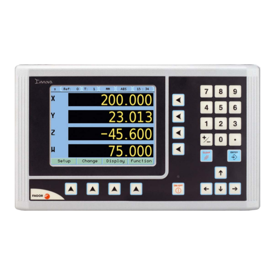
1 DRO description 1.1 Front plate: Keys for axes Keys for entering numeric values TFT screen Abort Validate Cursor keys Keys to open droplist buttons of the Power-off button FUNCTION BAR Power indicator LED 1.2 Turning the unit on and off It turns on automatically when applying voltage or after pressing the on/off key. -
Page 5: Main Screen Description
1.3 Main screen description: Display mode: Display units mm/inch INC/ABS Active reference Nr. Chronometer Set/Clear Active tool Nr. Probe ON STATUS BAR DISPLAY AREA FUNCTION BAR 1.4 Function bar The function bar gives access to the various functions offered by the DRO. 1.4.1 Access to functions: FUNCTION... -
Page 6: Dro Operation
2 DRO operation Display modes. Display Display 2.1.1 mm / inch Display mm / inch Toggle units between mm and inches. This toggle is possible if the installer parameters have been set as toggle . 2.1.2 inc / abs Display inc / abs Toggle between incremental and absolute feedback reading (counting). -
Page 7: Degrees / Degrees-Minutes-Seconds
2.1.2.3 Degrees / Degrees-Minutes-Seconds Display Deg / DMS Toggles the axis display units between degrees and degrees, minutes, seconds. 2.1.3 Rad / Diam Display Rad / Diam Toggles the X axis display between radius and diameter Set/Clear Display Set/Clear There are two ways (modes) to set a value (Set) on the display or zero it (Clear). 2.2.1 In "... -
Page 8: Machine Reference (Home) Search
Machine reference (home) search: Setup Home search Select axis. A red bar appears on that axis display indicating that it is waiting for a reference pulse. Move the selected axis until the DRO detects the reference mark. A green checkmark appears next to the axis display when the reference mark is properly detected (homed) and the axis display will show the position value preset in parameter "user offset", (see Reference). -
Page 9: Tool Compensation
2.4.1.3 Tool compensation: This DRO offers a function for compensating tool radius depending on the machining direction. Tool compensation on /off in this direction: Tool compensation on /off in this direction: Tool compensation on /off in this direction: Tool compensation on /off in this direction: When machining pockets, tool radius compensation is activated in two axes at the same time. -
Page 10: Changing The Reference
2.4.2.1 Changing the reference: Change Reference Changing from one reference to another. Tool Nr. It changes to the selected reference. 2.4.2.2 Setting part zero (datum) as instructed by the assistant: Change Reference Origin Setting part zero requires measuring at least 2 points. One point on each of the sides to be homed. -
Page 11: Setting Part Zero (Datum) Without Using The Assistant
2.4.2.3 Setting part zero (datum) without using the assistant: Change Reference Set a datum point at a corner other than the 3rd quadrant. Compensate for tool radius on the X axis. Touch with the tool on the side indicated in the figure. Set the X axis to zero. -
Page 12: Special Functions
Special functions. Function It gives access to the specific milling functions. 2.5.1 Cycles. The DRO allows storing 99 cycles, numbered from 1 to 99. The cycles may be executed, deleted or edited at will. The screen shows the data of the selected cycle so it can be identified easily. -
Page 13: Bolt-Hole Drilling
2.5.1.2 Bolt-hole drilling. Function Bolt-hole drilling It allows up to 99 holes to be drilled in a bolt-hole pattern in different planes (XY, XZ, YZ) without having to calculate the coordinates (X Y) of each hole, by simply keying in some basic data. -
Page 14: Go To
Go to 2.5.1.5 Function Go to This function is the alternative to the most commonly used positioning method consisting in presetting an incremental zero at a point and moving the axis until the display shows the desired coordinate. The Go to function may be used to do the same in the opposite direction, you enter the coordinates of the target point and the DRO screen shows these values with the negative sign. -
Page 15: Calculator Function
2.5.3 Calculator function Function Calculator It may be used to carry out mathematical and trigonometric operations as well as preset the desired axis with the result of the calculation or import the displayed coordinate values into the calculator to carry out math operations. Different types of calculators may be selected at the function bar: Arithmetic, trigonometric and for square functions. -
Page 16: Cycle Execution
View Engineering Drawing Consists of a top view and two sections with a mobile partition by pressing the arrow keys. View 2D views The 3D graphic may be rotated using the arrow keys. Opens the window for entering the actual (real) part Size dimensions. -
Page 17: Probe
The probe stores the data about the probed points in a USB memory. The probing data may be read and processed at a PC. The file containing the probed points is: FAGOR/DRO/PROBE/probe.csv The format of the generated file is “csv” (comma separated values) and may be easily imported into a spreadsheet. -
Page 18: Dro Installation
3 DRO installation There are two ways to mount the Innova 40i M: 1- Mounted on the support arm. 2- Built-in model. Mounting on the support arm. The DRO may be mounted at the desired height and may be oriented at will. The DRO is mounted on to the support arm using two set-screws. -
Page 19: Rear Panel
Rear panel On the back of the unit the following items may be found: * Three-prong power connector for AC and ground connection. * M6 mm terminal, for general machine ground connection. * Mounting bracket. * Feedback connectors: X1.-SUB-D HD type 15-pin female connector for 1st axis feedback device (scale or encoder). X2.-SUB-D HD type 15-pin female connector for 2nd axis feedback device (scale or encoder). -
Page 20: Connections
Connections 3.5.1 Connection of the feedback systems The feedback systems (linear or rotary encoders) are connected via SUB-D HD type 15-pin female connectors: X1 through X4. Characteristics of feedback inputs: X1, X2, X3 and X4: -Maximum feedback consumption: 250 mA at the +5V input. -Admits square-wave signal (TTL). -
Page 21: Probe Connection. Connector X5
3.5.2 Probe connection (connector X5) Either a 5 V or a 24 V probe may be connected. Characteristics of probe inputs X5: 5V probe input Typical value 0,25 mA. ? Vin = 5 V. High threshold (logic state 1) VIH: From +2.4 V DC on. Low threshold (logic state 0) VIL: Below +0.9 V DC. -
Page 22: Power And Machine Connection
Probe with a normally-open-contact output. Acts with an up flank. Probe with a normally-closed-contact output. Acts with an up flank. Interface with an open-collector output. Connection to +5 V. Acts with a down flank. Interface with an open-collector output. Connection to +24 V. Acts with a down flank. -
Page 23: Installation Parameters
Installation parameters 3.6.1 Accessing installation parameters Setup Home search Setup User Test Installer Password Language Color 231202 Feedback Compensation (type, axes, alarms) (encoders) (linear, multi-point) Setup Setup Gives access to setting installation and user parameters and to the test mode. The parameter setup is divided into three parts: 1- USER PARAMETERS: Parameters that may be modified by User... -
Page 24: Screen Color
3.6.2.2 Screen color Use the cursor keys to change the colors for the background, for the numbers, for the box, etc. ColorSet The default box shows the three preset options: 1- Default: Blue background with yellow numbers. 2- Color 1: Black background with yellow numbers. 3- Color 2: Green background, white box and green numbers. - Page 25 Axes option: Setup Setup Axes Install These parameters must be set for each axis. 1- Combine axes: It is possible to add/subtract any axis to/ from another axis. The factory setting is NO. Rotary axes cannot be combined. 2- Display resolution: It is the resolution of the DRO. It makes it possible to display the position with a coarser resolution than that of the feedback device, although the actual internal calculation is done with the finest resolution.
-
Page 26: Feedback
FAGOR Setup Setup Feedback Install Selecting Fagor feedback knowing the name or model of the linear encoder. Select axis. Select type of linear encoder, type of signal and type of reference pulse. To validate the data for that axis. Custom feedback selection:... - Page 27 1Vpp or TTL with distance-coded reference marks. Example: We wish to install a FAGOR GP linear encoder (1 Vpp and 20-micron-pitch graduated glass) with 1 micron resolution Graduation pitch (20, 40 or 100 µm)
-
Page 28: Compensation
* Mandatory Home search. When set to YES, every time the DRO is turned on, it forces a home search. It is recommended to set it to YES when the DRO uses positioning error compensation because if the compensated axis is not homed, the compensation will not be applied. -
Page 29: Test Mode
* Draw Graph: Function Draw Graph Draws a graph with the points and errors entered. It is recommended to check the graph to detect possible mistakes made when entering data. Note: The maximum slope for the compensation graph is ±0.8 mm/m 3.6.4 Test mode. -
Page 30: Appendix
Read the following safety measures in order to prevent damage to personnel, to this product and to those products connected to it. Fagor Automation shall not be held responsible for any physical or material damage derived from the violation of these basic safety regulations. - Page 31 Use proper Mains AC power cables. To avoid risks, use only the Mains AC cables recommended for this unit. Avoid electrical overloads In order to avoid electrical discharges and fire hazards, do not apply electrical voltage outside the range indicated in chapter 2 of this manual Ground connection In order to avoid electrical discharges, connect the ground terminals of all the modules to the main ground terminal.
-
Page 32: Warranty Terms
Within the warranty period, Fagor will repair or replace the products verified as being defective. FAGOR is committed to repairing or replacing its products from the time when the first such product was launched up to 8 years after such product has disappeared from the product catalog. -
Page 33: Material Returning Terms
The cardboard being used to make the box must have a resistance of 170 Kg (375 lb.). When sending it to a Fagor Automation office for repair, attach a label indicating the owner of the unit, person to contact, type of unit, serial number, symptom and a brief description of the problem.
Need help?
Do you have a question about the Innova 40i P-B and is the answer not in the manual?
Questions and answers