Sign In
Upload
Download
Table of Contents
Contents
Add to my manuals
Delete from my manuals
Share
URL of this page:
HTML Link:
Bookmark this page
Add
Manual will be automatically added to "My Manuals"
Print this page
×
Bookmark added
×
Added to my manuals
Manuals
Brands
East Tester Manuals
Measuring Instruments
ET4501
User manual
East Tester ET4501 User Manual
Lcr benchtop digital bridge
Hide thumbs
1
2
Table Of Contents
3
4
5
6
7
8
9
10
11
12
13
14
15
16
17
18
19
20
21
22
23
24
25
26
27
page
of
27
Go
/
27
Contents
Table of Contents
Bookmarks
Table of Contents
Table of Contents
1 Installation
2 Description
3 Quick Reference
Front Panel
Introduction of Keys
Power On/Off Key
Direction Key
Basic Function Keys
Introduction of Rear Panel
User Interface
Interface of Measurement Display
Interface of Measurement Setting
Interface of List Scanning
Interface of System Setting
4 Basic Function Operation
Parameter Selection
Frequency Selection
Level Selection
Offsets Selection
Range Selection
Output Impedance Selection
Measurement Display Speed Selection
Main Parameter Selection
Secondary Parameter Selection
Equivalent Mode Selection
List Scanning Function
Dcr Mode
Electrolytic Capacitor Mode
Relative Function
Data Retention Function
Data Recording Function (Maximum Value, Minimum Value, Average Value)错误!未定义书签
Backlight Brightness Setting
Power-On Parameter Setting
Buzzer Switch Setting
5 Basic Performance Indicators
Measurement Parameter
Equivalent Mode
Basic Accuracy
Dcr Measurement Accuracy
Test Signal Frequency
Test Signal Level
Output Impedance
Measurement Display Range
6 External Interface Instructions
Usb Interface
Rs232Interface
7 Scpi Command Reference
8 Precautions and Warranty
Advertisement
Quick Links
1
Description
2
Front Panel
3
Measurement Parameter
4
Scpi Command Reference
5
Usb Interface
Download this manual
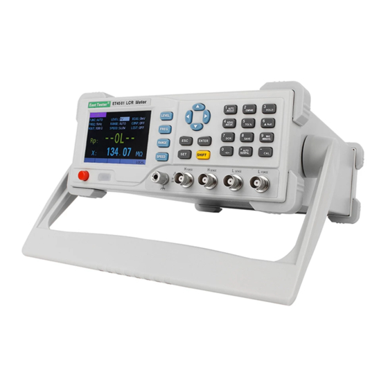
ET4501/4502/4510
LCR Benchtop Digital Bridge
User Manual
Hangzhou Zhongchuang Electron Co.,Ltd
No3, Kangle Road, Gongshu District, Hangzhou, Zhejiang, China
Tel: 0086-571-56770221 / 13396517215
Website:
www.easttester.com
Table of
Contents
Previous
Page
Next
Page
1
2
3
4
5
Advertisement
Table of Contents
Need help?
Do you have a question about the ET4501 and is the answer not in the manual?
Ask a question
Questions and answers
Related Manuals for East Tester ET4501
Measuring Instruments East Tester ET4510 User Manual
Lcr benchtop digital bridge (27 pages)
Measuring Instruments East Tester ET4502 User Manual
Lcr benchtop digital bridge (27 pages)
Measuring Instruments East Tester ET1080A User Manual
Handheld lcr meter (36 pages)
Measuring Instruments East Tester ET-2714 User Manual
Thermocouple calibrator (23 pages)
Measuring Instruments East Tester ETX-2710 User Manual
(33 pages)
Measuring Instruments East Tester ET430 Instructions For Use Manual
Lcr handheld bridge (36 pages)
Measuring Instruments East Tester ET432 Instructions For Use Manual
Lcr handheld bridge (36 pages)
Measuring Instruments East Tester ET433 Instructions For Use Manual
Lcr handheld bridge (36 pages)
Measuring Instruments East Tester ET3501 Operating Instructions Manual
Lcr digital electricbridge (111 pages)
Measuring Instruments East Tester ET3510 Operating Instructions Manual
Lcr digital electricbridge (111 pages)
Measuring Instruments East Tester ET1090 User Manual
Benchtop digital bridge (23 pages)
Measuring Instruments East Tester ET5406A+ User Manual
Single channel programmable dc electronic load (40 pages)
This manual is also suitable for:
Et4510
Et4502
Et45 series
Table of Contents
Print
Rename the bookmark
Delete bookmark?
Delete from my manuals?
Login
Sign In
OR
Sign in with Facebook
Sign in with Google
Upload manual
Upload from disk
Upload from URL


Need help?
Do you have a question about the ET4501 and is the answer not in the manual?
Questions and answers