Sign In
Upload
Download
Table of Contents
Contents
Add to my manuals
Delete from my manuals
Share
URL of this page:
HTML Link:
Bookmark this page
Add
Manual will be automatically added to "My Manuals"
Print this page
×
Bookmark added
×
Added to my manuals
Manuals
Brands
East Tester Manuals
Measuring Instruments
ET430
Instructions for use manual
East Tester ET430 Instructions For Use Manual
Lcr handheld bridge
Hide thumbs
1
2
Table Of Contents
3
4
5
6
7
8
9
10
11
12
13
14
15
16
17
18
19
20
21
22
23
24
25
26
27
28
29
30
31
32
33
34
35
36
page
of
36
Go
/
36
Contents
Table of Contents
Bookmarks
Table of Contents
Table of Contents
Safety
Instruction on Safety
Introduction
Overview of Front Panel
Front Panel
User's Interface
Measurement Interface
System Settings Interface
Test Port
Operation Instruction
Startup and Shutdown
Selection of Parameter
Selection of Frequency
Selection of Level
Selection of Internal Bias
Selection of Range
Selection of Measurement Speed
Selection of L/C/R/Z Main Parameters
Selection of X/D/Q/Θ/Esr Secondary Parameters
Selection of Tolerance
Selection of Nominal
Selection of Equivalent
DCR Mode
Electrolytic Capacitance Mode
Relative Mode
Reading Hold Mode (HOLD)
Data Recording Function (Maximum, Minimum, Average)
Comparator Function
Correction Function
Rapid Application Guide
Resistance Measurement
Capacitance Measurement
Inductance Measurement
Impedance Measurement
Telecommunication
Instrument Parameters
General Parameters
Measurement Accuracy
Accuracy Indicator
Accuracy Indicator 1(ET433)
Accuracy Indicator 2(ET432/ET431)
Accuracy Indicator 3(ET430 and ET430B)
Accuracy Indicator (DCR)
Maintenance
Overhaul
Clean
Advertisement
Quick Links
1
Table of Contents
2
Overview of Front Panel
3
Capacitance Measurement
Download this manual
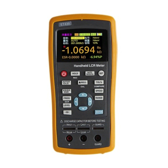
ET430/430B/431/432/433
LCR Handheld Bridge
Instruction for Use
Hangzhou Zhongchuang Electronics Co., Ltd.
Table of
Contents
Previous
Page
Next
Page
1
2
3
4
5
Advertisement
Table of Contents
Need help?
Do you have a question about the ET430 and is the answer not in the manual?
Ask a question
Questions and answers
Related Manuals for East Tester ET430
Measuring Instruments East Tester ET4501 User Manual
Lcr benchtop digital bridge (27 pages)
Measuring Instruments East Tester ET4510 User Manual
Lcr benchtop digital bridge (27 pages)
Measuring Instruments East Tester ET4502 User Manual
Lcr benchtop digital bridge (27 pages)
Measuring Instruments East Tester ET1080A User Manual
Handheld lcr meter (36 pages)
Measuring Instruments East Tester ET-2714 User Manual
Thermocouple calibrator (23 pages)
Measuring Instruments East Tester ETX-2710 User Manual
(33 pages)
Measuring Instruments East Tester ET432 Instructions For Use Manual
Lcr handheld bridge (36 pages)
Measuring Instruments East Tester ET433 Instructions For Use Manual
Lcr handheld bridge (36 pages)
Measuring Instruments East Tester ET3501 Operating Instructions Manual
Lcr digital electricbridge (111 pages)
Measuring Instruments East Tester ET3510 Operating Instructions Manual
Lcr digital electricbridge (111 pages)
Measuring Instruments East Tester ET1090 User Manual
Benchtop digital bridge (23 pages)
Measuring Instruments East Tester ET5406A+ User Manual
Single channel programmable dc electronic load (40 pages)
This manual is also suitable for:
Et430b
Et431
Et432
Et433
Table of Contents
Save PDF
Print
Rename the bookmark
Delete bookmark?
Delete from my manuals?
Login
Sign In
OR
Sign in with Facebook
Sign in with Google
Upload manual
Upload from disk
Upload from URL


Need help?
Do you have a question about the ET430 and is the answer not in the manual?
Questions and answers