
Related Manuals for East Tester ET5406A+


Summary of Contents for East Tester ET5406A+
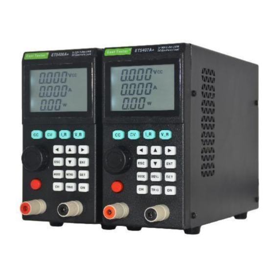
- Page 1 ET5406A+/ET5407A+SingleChannel Programmable DC Electronic Load User Manual Hangzhou Zhongchuang Electron Co., Ltd Zhejiang EastTester Measurement&Control Technology Co.,Ltd...
-
Page 2: Power Fuse
Product Basic Function ET5406A+/ET5407A+ programmable DC electronic load provides 1mV/10mV, 1mA/10mA high resolution and precision with superior performance. It is equipped with 9 common modes and complete test functions, which can be widely used in charger, switching power supply, linear power supply, battery and other production line testing. Key Features: User-friendly Design: ... - Page 3 Catalog 1. Quick Start ....................错误!未定义书签。 Product Basic Function ..................错误!未定义书签。 1.1. Front Panel LCD Display ..............错误!未定义书签。 1.2. Buttons on Front Panel ..............错误!未定义书签。 2. Funcitional operations ..................错误!未定义书签。 2.1. Mode Slection ..................错误!未定义书签。 2.2. Range Switching .................错误!未定义书签。 2.3. Channel Switching ................错误!未定义书签。 2.4.
- Page 4 6. SCAN Test Operation(SCAN) ....................21 6.1. Main Display Interface ...............错误!未定义书签。 6.2. Parameter Editting ................错误!未定义书签。 6.3. Working Status ...................错误!未定义书签。 7. BATTERY Test Operation(BATT) ............... 错误!未定义书签。 7.1. Main Display Interface ...............错误!未定义书签。 7.2. Parameter Editting ................错误!未定义书签。 7.3. Working Status ...................错误!未定义书签。 7.3.1. ex.:CC Discharge with Voltage Selected as the Cut-off Condition 错误!未定义书签。 8.
-
Page 7: Quick Start
ET5406A+/ET5407A+ Programmable DC Electronic Load - User Manual 1. Quick Start 1.1. Front Panel LCD Display The segment codes on the front panel are displayed below: Fig. 1-1-1 Complete Segment Code Display 1.2. Buttons on the Front Panel Fig. 1-2-1 Button Diagram... -
Page 8: Functional Operations
ET5406A+/ET5407A+ Programmable DC Electronic Load - User Manual Button Descriptions Below the display screen, there are 12 regular function buttons and 4 shortcut buttons, with the following specific operational functions. Regular Function Buttons ◄: Cursor Left button; and Delete button within the Historical Record Recall Interface; ►: Cursor Right button;... -
Page 9: Mode Selection
ET5406A+/ET5407A+ Programmable DC Electronic Load - User Manual the output of the power source, and then press the ON button to activate the load channel. Note!!! There must be a positive voltage between the red and black terminals. Any negative voltage input will prompt a reverse connection notification. Reverse connection may result in damage to the instrument itself or the tested power source. -
Page 10: Channel Switching
ET5406A+/ET5407A+ Programmable DC Electronic Load - User Manual or current range) to switch current range and choose V rAn (i.e., V Range or voltage range) to switch voltage range. During the switching of voltage range, the voltage limit will be reset to the maximum value allowed within the current range. -
Page 11: Load Parameters
ET5406A+/ET5407A+ Programmable DC Electronic Load - User Manual Fig. 2-5-1-1 Save Parameter Interface Press the [ENT] button to enter the parameter saving state, as shown in Fig. 2-5-1-2. The file name will be displayed in the second row and can be modified via the knob or cursor buttons. The file number will be displayed in the third row and it indicates the current entry number. -
Page 12: Current Range
ET5406A+/ET5407A+ Programmable DC Electronic Load - User Manual Within the non--system parameter setting interface, i.e., during operation mode, users can also swiftly switch between the high and low voltage ranges using the [V_R] button when the channel is inactive. Fig. 2-5-3-1 High and Low Voltage Ranges 2.5.4. - Page 13 ET5406A+/ET5407A+ Programmable DC Electronic Load - User Manual Fig. 2-5-5-1 Voltage/Current/Power Limits The current voltage and current ranges will also affect the setting range of the limits. In addition to the system settings, users can also set the voltage/current/power limits in the CC, CV, CP and CR modes.
-
Page 14: Start Settings
ET5406A+/ET5407A+ Programmable DC Electronic Load - User Manual please reduce the turn-off voltage first; if the turn-off voltage cannot be increased, please increase the starting voltage first. 2.5.8. Start Settings Start Settings, i.e. StArt can be used to set the dEFAU or LASt. dEFAU: default, each time the instrument is started, all parameters will be configured to their factory defaults. -
Page 15: Communication Mode
ET5406A+/ET5407A+ Programmable DC Electronic Load - User Manual Fig. 2-5-11-1 Backlight Brightness 2.5.12.RS485 Address RS485 Address (485Ad or 485 Address) can be set from 0 to 31 and will function only when the communication mode is set as 485. 0 represents the broadcast address. In 485 mode, all instruments will respond to address 0. Addresses 1 to 31 represent specific addresses. -
Page 16: System Information
ET5406A+/ET5407A+ Programmable DC Electronic Load - User Manual 2.5.15. Qualification Test and Its Limit Qualification Test (qUALI or quality) can be enabled or disabled. 2-5-15-1 Qualification Test Setting When the Qualification Test is enabled, the channel is active, and the tested voltage, current and power exceed the limits set for the test, the "OK"... -
Page 17: Constant Current (Cc)
ET5406A+/ET5407A+ Programmable DC Electronic Load - User Manual These four modes are considered the basic operation modes. After the channel is activated, all parameters other than the turn-off delay time can be edited and take immediate effect. 3.1. Constant Current (CC) In CC mode, the electronic load consumes a constant current, regardless of input voltage changes. - Page 18 ET5406A+/ET5407A+ Programmable DC Electronic Load - User Manual these maximum values are exceeded, the channel will be forcibly deactivated and the buttons will be locked, with OC, OV and OP prompted. Each time the voltage or current range is switched, the corresponding voltage or current limits will be reset to their maximum values.
-
Page 19: Constant Voltage (Cv)
ET5406A+/ET5407A+ Programmable DC Electronic Load - User Manual 3.2. Constant Voltage (CV) In CV mode, the electronic load will consume enough current to maintain the input voltage at the set voltage value. Fig. 3-2-1 Basic Display Interface When the Channel Is Activated in CV Mode Basic button operations and interface switching and display are the same with those in CC mode. -
Page 20: Main Display Interface
ET5406A+/ET5407A+ Programmable DC Electronic Load - User Manual changes, the load will adjust the current accordingly to maintain the load at the set resistance value. Fig. 3-4-1 Basic Display Interface When the Channel Is Activated in CR Mode After the channel is activated, users can press the arrow buttons [▲ ▼◄ ►] to select whether to display resistance and current alternately on the second line, or to display only current or resistance. - Page 21 ET5406A+/ET5407A+ Programmable DC Electronic Load - User Manual edited using the knob or arrow buttons. After the selection, press the [ENT] button again to edit the selected parameter. The following parameters can be edited. After setting the parameters, press the [ESC] button repeatedly to return to the main display interface.
-
Page 22: Operation State
ET5406A+/ET5407A+ Programmable DC Electronic Load - User Manual Fig. 4-2-5 A and B Pulse Width Time 4.3. Operation State After users press the [ON] button to activate the channel, it will exhibit different operation behaviors based on the specified settings. Continuous Mode (Cont): In this mode, after the test is initiated, the load can continuously switch between values A and B. - Page 23 ET5406A+/ET5407A+ Programmable DC Electronic Load - User Manual LIST test, the testing procedures and parameters for the device under test can be organized into a list and executed in sequence. Specific setting parameters include: defining the number of steps, step mode, loop switch, load mode for each step, load magnitude, delay time, comparison switch, upper limit, and lower limit.
- Page 24 ET5406A+/ET5407A+ Programmable DC Electronic Load - User Manual 5-2-1 Test Steps Step Mode: Continuous/Trigger. Set the step mode for test items. Continuous: Perform tasks sequentially and sustain the delay time in the current mode. Trigger: Enter the next mode upon receiving a trigger signal. 5-2-2 Test Steps Looping: Enabled/Disabled.
-
Page 25: Operation Status
ET5406A+/ET5407A+ Programmable DC Electronic Load - User Manual 5-2-5 Settings in Different Modes Comparison: Whether to compare the values from the current channel with the preset upper and lower limits after the test is initiated. Users can choose OFF (disabled), CUrr (current), voLt (voltage), PoWEr (power), and rES (resistance). - Page 26 ET5406A+/ET5407A+ Programmable DC Electronic Load - User Manual 5-3-1 Comparison Results The effect of the comparison value is similar to that of the Qualification Test. If the value falls within the specified range, the "OK" icon remains steady; if it exceeds the range, the "OK" icon flashes and the Buzzer sounds.
- Page 27 ET5406A+/ET5407A+ Programmable DC Electronic Load - User Manual 6-2-1 Scan Type For CC scan type, start value, end value, and step value are current values; For CV scan type, start value, end value, and step value are voltage values; For CP scan type, start value, end value, and step value are power values. Start Value: The initial setting value for the scan.
- Page 28 ET5406A+/ET5407A+ Programmable DC Electronic Load - User Manual Voltage Transition: dELtA. When the amplitude of voltage transition during operation exceeds the threshold setting value, the voltage, current, and power values of the load will be captured, and displayed on the measurement display interface; Drop: droP.
- Page 29 ET5406A+/ET5407A+ Programmable DC Electronic Load - User Manual channel will be automatically deactivated. After completing the test, users can select and observe various results from the scan using the knob or arrow buttons. If the threshold detection is triggered during the scanning process, the captured voltage, current, and power values can also be viewed.
- Page 30 ET5406A+/ET5407A+ Programmable DC Electronic Load - User Manual Fig. 7-1-1 Basic Electrical Parameters Fig. 7-1-2 Capacity AH and Energy WH Recorded from Last Measurement The recording time consists of hours on the first line, minutes on the second line and seconds on the third line.
- Page 31 ET5406A+/ET5407A+ Programmable DC Electronic Load - User Manual the selected parameter. The following parameters can be edited. After setting the parameters, press the [ENT] button repeatedly to return to the main display interface. Discharge Modes: In Battery mode, there are two discharge modes, CC (constant current discharge) or Cr (constant resistance discharge).
- Page 32 ET5406A+/ET5407A+ Programmable DC Electronic Load - User Manual For example, if the cut-off enable is set to 3, there are 3 cut-off voltage values that can be configured. If the instrument operates at this time, it will check if the measured voltage is less than cut-off voltage 1;...
- Page 33 ET5406A+/ET5407A+ Programmable DC Electronic Load - User Manual 7.3. Operation Status After setting the parameters, press the ON button to start the battery test. Once the cut-off condition is met, the channel will be automatically deactivated. Energy, capacity, and time values will be saved even after power outage, ensuring that the values from the last measurement are preserved.
- Page 34 ET5406A+/ET5407A+ Programmable DC Electronic Load - User Manual Fig. 7-3-1-1 Battery Discharge Settings As the battery discharges, its internal resistance increases and output voltage decreases. Therefore, users can use a lower current for discharge when the battery voltage decreases. Therefore, users can set the cutoff enable to 3. Set discharge current 1 to 3A and cutoff voltage 1 to 17V;...
-
Page 35: Other System Settings
ET5406A+/ET5407A+ Programmable DC Electronic Load - User Manual Over Power Protection Input power exceeds the power limit (detected for over 20ms) Over Temperature Protection The temperature of the heatsink exceeds 85° Reverse Polarity Prompt Input polarity is reversed Note: There’s only a prompt for reverse polarity, without any protection. 10. - Page 36 ET5406A+/ET5407A+ Programmable DC Electronic Load - User Manual If the LIST test result or the result of the qualification test is deemed satisfactory, the level is low; otherwise, the level is high. N1:When an external trigger is input, the Negative Edge 1 is triggered, with the low level being effective and maintained for more than 100ms.
-
Page 37: Technical Index
ET5406A+/ET5407A+ Programmable DC Electronic Load - User Manual Technical Index: MODEL ET5406A+ ET5407A+ Power 200W 200W Rated input Input voltage 0-120V 0-180V Input current 0-20A 0-30A Range 0.1~19.999V,0.1~120.00V 0.1~19.999V,0.1~180.00V CV mode Resolution 1mV,10mV Accuracy ±(0.05%+0.02%FS) Range 0~3.000A,0~20.00A 0~3.000A,0~30.00A Resolution 1mA,10mA CC mode Accuracy ±(0.05%+0.05%FS)... - Page 38 ET5406A+/ET5407A+ Programmable DC Electronic Load - User Manual capacity Resolution 1mA,10mA,10mΩ,1Ω Range of measurement Range Voltage 0~19.999V,0 ~120.00V 0~19.999V,0~180.00V read-back Resolution 1mV,10mV value Accuracy ±(0.05%+0.1%FS) Range Current 0~3.000A,0~20.00A 0~3.000A,0~30.00A read-back Resolution 1mA,10mA value Accuracy ±(0.05%+0.1%FS) ±(0.05%+0.1%FS) Range Power 200W read-back Resolution 10mW value...
- Page 39 ET5406A+/ET5407A+ Programmable DC Electronic Load - User Manual Hangzhou Zhongchuang Electron Co.,Ltd. Zhejiang EastTester Measurement&Control Technology Co.,Ltd Address: No 3, 4 floor, No 58 Yunhe Road, Leidian Town, Deqing Country, Huzhou, Zhejiang,China Postcode: 313219 Tel: 0086-0572-8832711 Tel: 400-0000-332 Website: www.east-tester.com...
Need help?
Do you have a question about the ET5406A+ and is the answer not in the manual?
Questions and answers