
Related Manuals for East Tester ET1080A


Summary of Contents for East Tester ET1080A
- Page 1 ET1080A/1080B/1080C/1080D/1080E Handheld LCR Meter User Manual Hangzhou Zhongchuang Electronics Co., Ltd.
- Page 2 Hangzhou Zhongchuang Electronics Co., Ltd. Adress: NO. 3 Kangle Road, Gongshu District, Hangzhou,Chiaa Postcode: 310015 Telephone: 0086-571-56861333 Fax: 0086-571-56861355 Website: http://www.cnheader.com http://www.easttester.com QQ: 2853705707, 2853705708...
-
Page 3: Table Of Contents
Contents 1. Safety............................. 1 2. Instruction on safety......................1 3. Introduction........................... 1 4. Overview of front panel.......................2 4.1 Front panel........................2 4.2 User’s interface......................3 4.2.1. Measurement interface................3 4.2.2 System settings interface................4 4.3 Test port........................4 5. Operation instruction......................4 5.1 Startup and shutdown....................4 5.2 Selection of parameter..................... -
Page 4: Safety
User’s Guide of ET43 Series Handheld Bridge 1. Safety These security measures are applicable to the operation and maintenance personnel who should pay attention to them during service and maintenance. Do not use in explosive environments Avoid using it in dusty environment, in direct sunlight, in environment with high humidity or strong electromagnetic radiation or other harsh environments. -
Page 5: Introduction
User’s Guide of ET43 Series Handheld Bridge Storage temperature: 0 ℃ ~ 40 ℃; Pollution degree: 3. Introduction ET1080 Series handheld LCR is a portable hand-held measuring instrument for measuring the parameters of inductors, capacitors, resistors and other components. It is small with a 5V lithium battery, suitable for table-type application. -
Page 6: Overview Of Front Panel
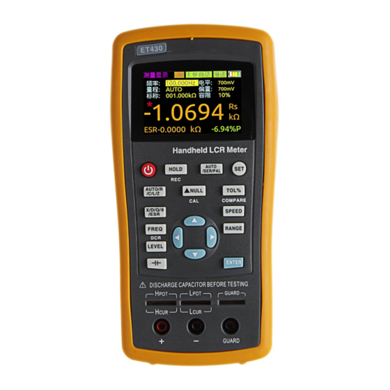
4. Overview of front panel Figure 1 Front panel (with ET431 as an example) 4.1 Front panel The front panel is described below, taking ET1080C as an example. See figure 1 (Note: the long press in the manual indicates to press and hold the key for more than 2 seconds. There is the short press and long press for the multifunction key, but only short press for other keys) 1 Display... -
Page 7: User's Interface
13 Measuring speed shortcut key to quickly switch the required measurement speed. 14 Range shortcut key to quickly switch the required range. 15 Arrow keys left and right arrow keys to control the movement of the cursor; up and down arrow keys to select the parameter. 16 Enter key to confirm the selection of a certain parameter or function. -
Page 8: System Settings Interface
4.2.2 System settings interface Figure 3 system settings interface On the system settings interface users can view the product model, serial number and version number. The language, automatic power-off, brightness, power-on, and buzzer can be set. 4.3 Test port ET1080 Series uses the 3- and 5-terminal test ports at the same time, which is to combine convenience and high accuracy for the test. -
Page 9: Selection Of Parameter
instrument. 5.2 Selection of parameter 5.2.1 Selection of frequency ET1080 Series handheld LCR applies AC test signal to the DUT for measurement. Frequency is one of the main parameters of the AC source. Due to the presence of the non-ideal and distributed parameters of elements, and the impact of the distributed parameters between the test end, the same element may have different results with different test frequencies. -
Page 10: Selection Of Internal Bias
5.2.3 Selection of internal bias ET1080Series offers internal bias 0-500mV, the DC bias voltage with stepping of 1mV (ET1080B/ET1080A has no such function). When the test function is DCR, the bias is 800mV. There are two ways to change the bias voltage:... -
Page 11: Selection Of Measurement Speed
5.2.5 Selection of measurement speed Turn on the instrument and the measurement display is shown, press SPEED to switch to the next measurement speed (fast, medium, slow). Above the status bar the corresponding measurement speed is displayed. Fast (4 times / s), the speed (2 times / s), Slow (1 time / s). -
Page 12: Selection Of Nominal
Press AUTO/SER/PAL to switch to the next equivalent (SER, PAL). 5.3. DCR mode ET1080 Series has the DCR mode except for ET1080B/ET1080A. Long press FREQ to enter the DCR mode, as shown in figure 9. SLOW... -
Page 13: Relative Mode
press -|(- to enter the electrolytic capacitance mode, as shown in figure 10. Figure 10 5.5. Relative mode Short press ▲NULL to turn on the relative function and the current value is used as reference. The reference value and relative value will be shown respectively on the secondary and main display. -
Page 14: Comparator Function
5.8 Comparator function See 5.2.8 Selection of tolerance and 5.2.9 Selection of nominal value. 5.9 Correction function The correction function applies to the open and short circuit. By correcting it can effectively reduce the error of distributed parameters caused by the test line. The short circuit correction can reduce the impact of the contact resistance and lead resistance on the measurement of low impedance element;... -
Page 15: Resistance Measurement
Do not measure the charged capacitor, or it may cause damage to the instrument. In case of measurement of on-board devices, make sure the power is turned off. The active circuit cannot be measured directly. When used in the dusty environment, the instrument is easy to gather dirt, so it should be cleaned periodically to protect the test port to prevent the dust from entering the instrument. -
Page 16: Capacitance Measurement
Figure 16 3. Insert the resistor into the test notch, or choose the appropriate test accessories (rubber plug - alligator clip, Kelvin test fixture, etc.) and connect it with the measured resistance; 4. Press the FREQ key to select the desired test frequency, press LEVEL to select the desired level;... -
Page 17: Inductance Measurement
SLOW MEAS DISP Freq: 1kHz 1kHz Level: 600mV Range:AUTO Bias: -263.12 -|(- -0.4172 Figure 18 3. Insert the capacitor into the test notch, or choose the appropriate test accessories (rubber plug - alligator clip, Kelvin test fixture, etc.) and connect it with the measured capacitor;... -
Page 18: Impedance Measurement
Figure 20 3. Insert the inductor into the test notch, or choose the appropriate test accessories (rubber plug - alligator clip, Kelvin test fixture, etc.) and connect it with the measured inductor; 4. Press the FREQ key to select the desired test frequency, press LEVEL to select the desired level;... - Page 19 Connect the instrument to the PC: 1. Locate the USB driver software in the CD. 2. Use the Mini-USB cable to connect the instrument to the USB port of the PC, shown in Figure 22, press and hold the power key to start the instrument. 3.
- Page 20 Terminator: the command line sent from the PC to the instrument must end with the specified terminator. Only after the instrument receives the terminator will it analyze and process the command string. The terminator is 0x0a. Query return format: when the instrument responds to a query command, it will return the search results: <Result>...
-
Page 21: Instrument Parameters
Here are the general indicators and measurement accuracy indicators for ET43 series handheld LCR, which apply to the ET43 Series. Disclaimer: These parameters are subject to change without notice! 8.1 General parameters Model ET1080B ET1080A ET1080C ET1080D ET1080E 100Hz, 100Hz, 120Hz,... - Page 22 Ac-- calibration accuracy Ab-- basic accuracy Kz-- impedance scaling factor Kl-- cable length factor Kt-- temperature factor The accuracy of D The accuracy of D—De is: when Dx≤0.1: Dx-- D measured Ae-- relative accuracy of R, C, L, Z, and X When Dx>...
- Page 23 Dx-- D measured Xx-- X measured (Ω) De -- relative accuracy of D f --test frequency (Hz) Cx—measured C (F) Lx—measured L (H) The accuracy of ESR ESR is the equivalent series resistance like Rs. Basic accuracy The basic accuracy of the instrument is 0.2; with the changes of the test frequency and the impedance of DUT, the basic accuracy will decline, the basic accuracy and its application are shown in the table below.
- Page 24 Accuracy factor This section contains all the accuracy correction factors: Impedance scaling factor Kz, temperature factor Kc, calibration factor Kf, cable length factor Kl. Frequen Kz(Zm<500Ω) Kz(Zm≧500Ω) cy/Hz Less than to 100k Greater ...
-
Page 25: Accuracy Indicator
5*10 *(1+0.05fm) 5*10 *(1+0.05fm) 1*10 *(1+0.05fm) Note: fm in the table indicates the frequency of the test signal ( unit: kHz ) 8.3 Accuracy indicator Notes: Ambient temperature: 20 ℃ ± 2 ℃ , humidity: ≤80% R.H; Preheat the instrument for at least 30 minutes before the test; ... -
Page 26: Accuracy Indicator 2(Et432/Et431)
8.3.2 Accuracy indicator 2(ET1080D/ET1080C) The following accuracy applies to the test level of 0.6Vrms, if the test level is 0.3Vrms, multiply the accuracy by 2; If the test level is 0.1Vrms, multiply the accuracy by 5 (Z> 0.5Ω ) or by 8 (Z≤0.5Ω); Hangzhou Zhongchuang Electronics Co., Ltd. - Page 27 Capacitance C and loss D 100Hz/120Hz Equivalent mode Range Range of display Accuracy Ce Accuracy De recommended 4.000mF∼20.000mF 20mF 5.00%+5 digits 0.0500 Series 400.0μF∼3.9999mF 1.00%+3 digits 0.0100 Series 400μF 40.00μF∼399.99μF 0.30%+2 digits 0.0030 Series 40μF 4.000μF∼39.999μF 0.20%+2 digits 0.0020 Series 4μF 400.0nF∼3.9999μF...
- Page 28 Series 40.00μF∼100.00μF 100μF 4.00%+5 digits 0.0400 40μF 4.000μF∼39.999μF 2.0%+3 digits 0.0200 Series 4μF 400.0nF∼3.9999μF 0.60%+2 digits 0.0060 Series 40.00nF∼399.99nF 400nF 0.3%+2 digits 0.0030 Series 40nF 4.000nF∼39.999nF 0.3%+2 digits 0.0030 ------ 400.0pF∼3.9999nF 0..3%+2 digits 0.0030 Parallel 400pF 40.00pF~399.99pF 0.6%+3 digits 0.0060 Parallel 40pF 0.000pF~39.999pF...
- Page 29 400.0mH∼3.9999H 0.20%+2 digits 0.0020 Parallel 400mH 40.00mH∼399.99mH 0.2%+2 digits 0.0020 ------ 4.000mH∼39.999mH 40mH 0.2%+2 digits 0.0020 Series 400.0uH∼3.9999mH 0.4%+3 digits 0.0040 Series 400uH 0.0uH~399.9uH 1.4%+5 digits ------ Series 10kHz Equivalent Accuracy Range Range of display Accuracy Le mode recommended 400.0mH∼999.9mH 0.80%+3 digits 0.0080...
- Page 30 Accuracy Equivalent mode Range Range of display Accuracy Ze recommended 20MΩ 4.000MΩ~20.000MΩ 3.0%+5 digits 1.1° Parallel 4MΩ 400.0kΩ~3.9999MΩ 1.2%+3 digits 0.7° Parallel 400kΩ 40.00kΩ~399.99kΩ 0.3%+3 digits 0.2° Parallel 40kΩ 4.000kΩ~39.999kΩ 0.2%+2 digits 0.1° ------ 4kΩ 400.0Ω~3.9999kΩ 0.2%+2 digits 0.1° Series 400Ω...
-
Page 31: Accuracy Indicator 3(Et430 And Et430B)
8.3.3 Accuracy indicator 3(ET1080B and ET1080A) See 8.2 for notes. Capacitance C and loss D 100Hz/120Hz Equivalent mode Range Range of display Accuracy Ce Accuracy De recommende Series 4.000mF∼20.000mF 20mF 8.00%+5 digits 0.0800 400.0μF∼3.9999mF 2.00%+3 digits 0.0200 Series 400μF 40.00μF∼399.99μF... - Page 32 40pF 0.00pF~39.99pF 2.5%+5 digits ------ Parallel 40kHz Equivalent Range Range of display Accuracy Ce Accuracy De mode recommended Series 40.00μF∼100.00μF 100μF 6.00%+5 digits 0.0600 40μF 4.000μF∼39.999μF 4.0%+3 digits 0.0400 Series 4μF 400.0nF∼3.9999μF 1.0%+2 digits 0.0100 Series 400nF 40.00nF∼399.99nF 0.6%+2 digits 0.0060 Series 40nF...
- Page 33 0uH∼3.999mH 3.0%+5 digits ------ Series 1kHz Equivale Accuracy nt mode Range Range of display Accuracy Le recomm ended 100H 40.00H∼100.00H 2.0%+3 digits 0.0200 Parallel 4.000H∼39.999H 0.60%+2 digits 0.0060 Parallel 400.0mH∼3.9999H 0.40%+2 digits 0.0040 Parallel 400mH 40.00mH∼399.99mH 0.4%+2 digits 0.0040 ------ 4.000mH∼39.999mH 40mH 0.4%+2 digits...
- Page 34 recommended 100mH 40.00mH∼399.99mH 2.5%+2 digits 0.0250 Parallel 40mH 4.000mH∼39.999mH 1.5%+2 digits 0.0150 Parallel 400.0uH∼3.9999mH 1.0%+2 digits 0.0100 ------ 400uH 40.00uH~399.99uH 1.0%+2 digits 0.0100 Series 40uH 4.000uH~39.999uH 1.5%+5 digits 0.0150 Series 0.000uH~3.999uH 4%+10 digits ------ Series Impedance Z and phase angle ...
-
Page 35: Accuracy Indicator
4MΩ 400.0kΩ~3.9999MΩ 4.0%+10 digits 2.3° Parallel 400kΩ 40.00kΩ~399.99kΩ 1.5%+4 digits 0.9° Parallel 40kΩ 4.000kΩ~39.999kΩ 1.0%+2 digits 0.6° Parallel 4kΩ 400.0Ω~3.9999kΩ 0.7%+2 digits 0.4° ------ 400Ω 40.00Ω~399.99Ω 0.7%+2 digits 0.4° Series 40Ω 4.000Ω~39.999Ω 1.0%+5 digits 0.6° Series 4Ω 0.4000Ω~3.9999Ω 3.0%+10 digits 1.7°... - Page 36 be removed. Prevent water or other liquids from entering the instrument through the test slot, keys, or other joints, if it happens by accident, you should immediately stop using it and remove the power supply and battery. Please clean with a soft cloth and diluted neutral detergent, and carefully wipe the dirty parts to prevent scratches on the surface.
Need help?
Do you have a question about the ET1080A and is the answer not in the manual?
Questions and answers