
Related Manuals for Aaeon PCM-5335


Summary of Contents for Aaeon PCM-5335
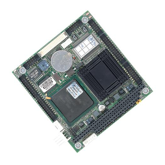
- Page 1 PCM-5335 All In One NS Geode GX1 with SVGA/ LCD/ Ethernet Interface PC/ 104 CPU Module PCM-5335 Rev. B Manual Oct. 2003...
- Page 2 AAEON, assumes no liabilities resulting from errors or omissions in this document, or from the use of the information contained herein. AAEON reserves the right to make changes in the product design without notice to its users.
- Page 3 P C / 1 0 4 M o d u l e P C M - 5 3 3 5 Acknowledgments All other product names or trademarks are properties of their respective owners. AMD is a trademark of Advanced Micro Devices, Inc. AMI is a trademark of American Megatrends, Inc., Award is a trademark of Award Software International, Inc.
- Page 4 P C M - 5 3 3 5 Packing List Before you begin installing your card, please make sure that the following materials have been shipped: • 1 PCM-5335 PC/104 CPU Module • 1 Quick Installation Guide • 1 CD-ROM for manual (in PDF format), drivers, and utility •...
-
Page 5: Table Of Contents
P C / 1 0 4 M o d u l e P C M - 5 3 3 5 Contents Chapter 1 General Information 1.1 Introduction..................1-2 1.2 Features....................1-3 1.3 Specifications..................1-4 Chapter 2 Quick Installation Guide 2.1 Safety Precautions................2-2 2.2 Location of Connectors and Jumpers.......... - Page 6 P C / 1 0 4 M o d u l e P C M - 5 3 3 5 2.20 COM1 RS-232 Connector (CN10)..........2-22 2.21 Floppy Connector (CN11)............... 2-23 2.22 COM1 RS-232/422/485 Connector (CN12)........ 2-25 2.23 TTL LCD Connector (CN13)............2-26 2.24 10/100Base-T Ethernet Connector (CN14).........
-
Page 7: Chapter 1 General Information
P C / 1 0 4 M o d u l e P C M - 5 3 3 5 Chapter General Information 1- 1 Chapter 1 General Information... -
Page 8: Introduction
It uses a NS CS5530A chipset which supports TFT LCDs. It offers all the functions of AT-compatible industrial computers on a single board. The PCM-5335 comes with an embedded high-performance GX1-300 processor onboard. For maximum performance, the PCM-5335 Series also supports an SDRAM SODIMM sock et that can accept up to 512 MB memory. -
Page 9: Features
P C / 1 0 4 M o d u l e P C M - 5 3 3 5 1.2 Features • Onboard low power NS Geode GX1 300MHz CPU • Support 18-bit TFT panels • Onboard 10/100Base-T Fast Ethernet •... -
Page 10: Specifications
P C / 1 0 4 M o d u l e P C M - 5 3 3 5 1.3 Specifications System Geode GX1-300 (low-power) processor System Memory SDRAM SODIMM x 1, up to 512MB Chipset NC CS5530A I/O Chipset Windbond W83977F. - Page 11 P C / 1 0 4 M o d u l e P C M - 5 3 3 5 • Operating Temperature: 32 to 140℉ (0 to 60℃) • MIO : IDE x 1, FDD x 1, KB x 1 , Mouse x 1, RS-232 x 2, Parallel x 1 •...
- Page 12 PC/104 Module P C M - 5 3 3 5 Chapter Quick Installation Guide Notice: The Quick Installation Guide is derived from Chapter 2 of user manual. For other chapters and further installation instruction s, please refer to the user manual CD -ROM that came with the product.
-
Page 13: Safety Precautions
P C / 1 0 4 M o d u l e P C M - 5 3 3 5 2.1 Safety Precautions Always completely disconnect the power cord from your board whenever you are working on it. Do not make connections while the power is on, because sensitive electronic components can be damaged by a sudden rush of power. -
Page 14: Location Of Connectors And Jumpers
P C / 1 0 4 M o d u l e P C M - 5 3 3 5 2.2 Location of Connectors and Jumpers Locating connectors and jumpers (component side) Chapter 2 Quick Installation Guide 2 - 3... - Page 15 P C / 1 0 4 M o d u l e P C M - 5 3 3 5 Locating connectors (solder side) 2 - 4 Chapter 2 Quick Installation Guide...
-
Page 16: Mechanical Drawing
P C / 1 0 4 M o d u l e P C M - 5 3 3 5 2.3 Mechanical Drawing Mechanical drawing (component side) 2 - 5 Chapter 2 Quick Installation Guide... - Page 17 P C / 1 0 4 M o d u l e P C M - 5 3 3 5 Mechanical Drawing (solder side) 2 - 6 Chapter 2 Quick Installation Guide...
-
Page 18: List Of Jumpers
P C / 1 0 4 M o d u l e P C M - 5 3 3 5 2.4 List of Jumpers The board has a number of jumpers that allow you to configure your system to suit your application. The table below shows the function of each jumper: Jumpers Label... -
Page 19: List Of Connectors
P C / 1 0 4 M o d u l e P C M - 5 3 3 5 2.5 List of Connectors The board has a number of connectors that allow you to configure your system to suit your application. The table below shows the function of each connector: Connectors Label... -
Page 20: Jumper Setting
P C / 1 0 4 M o d u l e P C M - 5 3 3 5 2.6 Jumper Setting You configure your card to match the needs of your application by setting jumpers. A jumper is the simplest kind of electric switch. It consists of two metal pins and a small metal clip (often protected by a plastic cover) that slides over the pins to connect them. -
Page 21: Clear Cmos (Jp1)
P C / 1 0 4 M o d u l e P C M - 5 3 3 5 2.7 Clear CMOS (JP1) Warning: To avoid damaging the computer, always turn off the power supply before setting “ Clear CMOS.” Before turning on the power supply, set the jumper back to “Normal.”... -
Page 22: Lcd Voltage Selection (Jp4)
P C / 1 0 4 M o d u l e P C M - 5 3 3 5 2.10 LCD Voltage Selection (JP4) You can select the LCD voltage by setting JP4. The following chart shows the available options. J P 4 Function +3.3V (Default) -
Page 23: External Power Connector (Cn2)
P C / 1 0 4 M o d u l e P C M - 5 3 3 5 2.12 External Power Connector (CN2) This supplies secondary power to devices that require -5V and -12V. Signal -12V 2 - 12 Chapter 2 Quick Installation Guide... -
Page 24: Pc/104 Connector (Cn3)
P C / 1 0 4 M o d u l e P C M - 5 3 3 5 2.13 PC/104 Connector (CN3) The PCM-5335’ s PC/104 connectors give you the flexibility to attach PC/104 modules. Signal Signal #SBHE... -
Page 25: Keyboard/ Mouse Connector (Cn4)
P C M - 5 3 3 5 2.14 Keyboard/ Mouse Connector (CN4) The PCM-5335 board provides a pin head er keyboard connector, which supports both a keyboard and a PS/2 style mouse. In most cases, especially in embedded applications, a keyboard is not used. If... -
Page 26: Pc/104 Connector (Cn5)
P C / 1 0 4 M o d u l e P C M - 5 3 3 5 2.15 PC/104 Connector (CN5) The PCM-5335’ s PC/104 connectors give you the flexibility to attach PC/104 modules. Signal Signal #IOCHCHK... - Page 27 P C / 1 0 4 M o d u l e P C M - 5 3 3 5 (Continued) Signal Signal SA14 #DACK1 SA13 DRQ1 SA12 #REFRESH SA11 SYSCLK SA10 IRQ7 IRQ6 IRQ5 IRQ4 IRQ3 #DACK2 BALE 2 - 16 Chapter 2 Quick Installation Guide...
-
Page 28: Usb Connector (Cn6)
P C M - 5 3 3 5 2.16 USB Connector (CN6) The PCM-5335 board provides two USB (Universal Serial Bus) interfaces, which give complete plug and play and also hot attach/detach for up to 127 external devices. The USB interfaces comply with USB specification rev. -
Page 29: Vga Connector (Cn7)
P C / 1 0 4 M o d u l e P C M - 5 3 3 5 2.17 VGA Connector (CN7) The PCM -5335 board's SVGA interface can facilitate conventional CRT displays. The card has a connector to support CRT VGA monitors. -
Page 30: Parallel Port Connector (Cn8)
2.18 Parallel Port Connector (CN8) Normally, the parallel port is used to connect the board to a printer. The PCM-5335 includes a multi-mode (ECP/EPP/SPP) parallel port. It is accessed via CN8, a 26-pin flat-cable connector. You will need an adapter cable if you use a traditional DB-25 connector. -
Page 31: Ide Connector (Cn9)
P C / 1 0 4 M o d u l e P C M - 5 3 3 5 2.19 IDE Connector (CN9) The built-in Enhanced IDE (Integrated Device Electronics) controller supports up to two IDE devices, including CD-ROM drives, tap e backup drives, a large hard disk drive and other IDE devices. - Page 32 P C / 1 0 4 M o d u l e P C M - 5 3 3 5 Signal Signal #RESET DATA7 DATA8 DATA6 DATA9 DATA5 DATA10 DATA4 DATA11 DATA3 DATA12 DATA2 DATA13 DATA1 DATA14 DATA0 DATA15 #IOW #IOR IOREADY #DACK...
-
Page 33: Com1 Rs-232 Connector (Cn10)
P C / 1 0 4 M o d u l e P C M - 5 3 3 5 2.20 COM1 RS-232 Connector (CN10) Different devices implement the RS-232 standard in different ways. If you are having problems with a serial device, be sure to check the pin assignments below for the connector. -
Page 34: Floppy Connector (Cn11)
P C M - 5 3 3 5 2.21 Floppy Connector (CN11) You can attach one 3.5” floppy drive to the PCM-5335's onboard controller. A 34-pin flat-cable connector is fitted on one end of the cable converter, while the other end has one floppy disk drive connector. - Page 35 P C / 1 0 4 M o d u l e P C M - 5 3 3 5 Signal Signal #REDWC GN D #DS1 #INDEX #MOTOR A #DRIVE SELECT B #DRIVE SELECT A #MOTOR B #DIR #STEP #WRITE DATA #WRITE GATE #TRACK0 #WRITE PROTECT...
- Page 36 P C / 1 0 4 M o d u l e P C M - 5 3 3 5 2.22 COM2 RS-232/422/485 Connector (CN12) Different devices implement the RS-232/422/485 standard in different ways. If you are having problems with a serial device, be sure to check the pin assignments below for the connector.
-
Page 37: Ttl Lcd Connector (Cn13)
P C / 1 0 4 M o d u l e P C M - 5 3 3 5 2.23 TTL LCD Connector (CN13) CN13 is a 40-pin dual-in-line header and is used to connect a LCD display. Signal Signal +3.3V +3.3V... -
Page 38: 10/100Base-T Ethernet Connector (Cn14)
The PCM-5335 is equipped with a high performance 32-bit PCI-bus Fast Ethernet interface which is fully compliant with IEEE 802.3u 10/100Base-T specifications. It is supported by all major network operating systems. 10/100Base-T connects to the PCM-5335 via an adapter cable to the 10-pin 2 mm connector. Signal Signal... -
Page 39: Compactflash Socket (Cn16)
P C M - 5 3 3 5 2.26 CompactFlash Socket (CN16) The PCM-5335 is equipped with a CompactFlash type I socket on the solder side, which supports the IDE interface CompactFlash card. The socket itself is specially designed to prevent any incorrect installation of the CompactFlash card. - Page 40 P C / 1 0 4 M o d u l e P C M - 5 3 3 5 Signal Signal DATA3 DATA4 DATA5 DATA6 DATA7 #CS1 ADDR2 ADDR1 ADDR0 DATA0 DATA1 DATA2 DATA11 DATA12 DAT A13 DATA14 DATA15 #CS3 #IOR #IOW...
-
Page 41: Chapter 3 Award Bios Setup
P C / 1 0 4 M o d u l e P C M - 5 3 3 5 Chapter Award BIOS Setup Chapter 3 Award BIOS Setup... - Page 42 The CMOS memory has lost power and the configuration information has been erased. The PCM-5335 CMOS memory has an integral lithium battery backup. The battery backup should last ten years in normal service. However, you will need to replace the complete unit when it finally runs down.
- Page 43 P C / 1 0 4 M o d u l e P C M - 5 3 3 5 3.2 Award BIOS setup Awards BIOS ROM has a built-in Setup program that allows users to modify the basic system configuration. This type of information is stored in battery-backed CMOS RAM so that it retains the Setup information when the power is turned off.
- Page 44 P C / 1 0 4 M o d u l e P C M - 5 3 3 5 Standard CMOS setup When you choose the STANDARD CMOS SETUP option from the INITIAL SETUP SCREEN menu, the screen shown below is displayed.
- Page 45 P C M - 5 3 3 5 BIOS features setup By choosing the BIOS FEATURES SETUP option from the INITIAL SETUP SCREEN menu, the screen below is displayed. This sample screen contains the manufacturer’s default values for the PCM-5335. 3 - 5 Chapter3 Award BIOS Setup...
- Page 46 P C M - 5 3 3 5 Chipset features setup By choosing the CHIPSET FEATURES SETUP option from the INITIAL SETUP SCREEN menu, the screen below is displayed. This sample screen contains the manufacturer’s default values for the PCM-5335. 3 - 6 Chapter3 Award BIOS Setup...
- Page 47 P C M - 5 3 3 5 Power management setup By choosing the POWER MANAGEMENT SETUP option from the INITIAL SETUP SCREEN menu, the screen below is displayed. This sample screen contains the manufacturer’s default values for the PCM-5335. 3 - 7 Chapter3 Award BIOS Setup...
- Page 48 P C M - 5 3 3 5 PnP/PCI configuration By choosing the PnP/PCI CONFIGURATION option from the Initial Setup Screen menu, the screen below is displayed. This sample screen contains the manufacturer’s default values for the PCM-5335. 3 - 8 Chapter3 Award BIOS Setup...
- Page 49 By choosing the INTEGRATED PERIPHERALS option from the INITIAL SETUP SCREEN menu, the screen below is displayed. This sample screen contains the manufacturer’s default values for the PCM-5335. The PANEL TYPE by default supports a 18-bit 640 x 480 TFT LCD panel display. 3 - 9...
- Page 50 P C / 1 0 4 M o d u l e P C M - 5 3 3 5 Change password To change the password, choose the PASSWORD SETTING option from the Setup main menu and press <Enter>. If the CMOS is bad or this option has never been used, a default password is stored in the ROM.
-
Page 51: Chapter 4 Driver Installation
P C / 1 0 4 M o d u l e P C M - 5 3 3 5 Chapter Driver Installation Chapter 4 Driver Installation... -
Page 52: Installation 2
P C / 1 0 4 M o d u l e P C M - 5 3 3 5 The PCM-5335 comes with a CD-ROM which contains most of drivers and utilities of your needs. There is several installation ways depends on the driver package under different Operating System application. -
Page 53: Installation 3
P C M - 5 3 3 5 4.2 Installation 2: Applicable for Windows 9x/ME Insert the PCM-5335 CD-ROM into the CD-ROM Drive. Click on Start button, select the Settings, then click on the Control Panel icon. Double click on the Add/Remove Hardware icon and Add New Hardware Wizard will appear. - Page 54 P C M - 5 3 3 5 4.3 Installation 3: Applicable for Windows NT 4.0 Insert the PCM-5335 CD Diskette into the CD-ROM Drive. Start system with Windows NT 4.0 installed. IMPORTANT: When the "Please select the operating system to start..."...
-
Page 55: Appendix A Programming The Watchdog Timer
P C / 1 0 4 M o d u l e P C M - 5 3 3 5 Appendix Programming the Watchdog Timer Appendix A Programming the Watchdog Timer... - Page 56 P C / 1 0 4 M o d u l e P C M - 5 3 3 5 Programming the watchdog timer The PCM-5335 contains a watchdog timer reset pin (GP16). All reference material can be found below. ======================================== ** Title: WatchDog Timer Setup Utility (for W83977 GP16) ** Company: AAEON Technology Inc.
- Page 57 P C / 1 0 4 M o d u l e P C M - 5 3 3 5 outportb(IO_INDEX_PORT, UNLOCK_DATA); void ExitConfigMode() outportb(IO_INDEX_PORT, LOCK_DATA); void SelectDevice(unsigned char device) outportb(IO_INDEX_PORT, DEVICE_REGISTER); outportb(IO_DATA_PORT, device); unsigned char ReadAData(short int reg) outportb(IO_INDEX_PORT, reg); return (inportb(IO_DATA_PORT));...
- Page 58 P C / 1 0 4 M o d u l e P C M - 5 3 3 5 //Set Register F3 //keyboard and mouse interrupt reset Enable //When Watch -Dog Time-out occurs,Enable POWER LED output WriteAData(0xF3, 0x0E); // set counter counts in second (or minute) // Register F4 Bit 6 = 0/1 (minutes/seconds) // For w83977EF only WriteAData(0xF4, 0x42);...
- Page 59 P C / 1 0 4 M o d u l e P C M - 5 3 3 5 else if(watch_dog_output_GP==16) //Set Register E6 to define GP16 WriteAData(0xE6, 0x0A); //Set Device Active WriteAData(0x30, 0x01); //Select Device 8 SelectDevice(8); //caution:skip this step will be a mistake!! if (watch_dog_output_GP==12) //Set Register 2A (PIN 57) Bit 7 = 0/1 (KBLOCK/GP12)
- Page 60 *ptr; printf("WinBond 83977 WatchDog Timer Setup Utility Version 1.0 \n"); printf("Copyright (c) 2000 AAEON Technology Inc. \n"); printf("This version only for W83977 that using GP%d to Reset System.\n",watch_dog_output_GP); if (argc == 1) printf("\n Syntax: WATCHDOG [time] \n");...
Need help?
Do you have a question about the PCM-5335 and is the answer not in the manual?
Questions and answers