Table of Contents
Advertisement
Quick Links
M i n i P C I D V I t o T T L M o d u l e
Notice
This guide is designed for experienced users to setup the
system in the shortest time.
Safety Precautions
Part No. 2007V01B10
Always completely disconnect the power cord
from your board whenever you are working on it.
Do not make connections while the power is on,
because a sudden rush of power can damage
sensitive electronic components.
Always ground yourself to remove any static
charge before touching the board. Modern
electronic devices are very sensitive to static
electric charges. Use a grounding wrist strap at
all times. Place all electronic components on a
static-dissipative surface or in a static-shielded
bag when they are not in the chassis
P E R - V 0 1 B
Printed in Taiwan
PER-V01B Quick Installation Guide
Sep. 2005
Advertisement
Table of Contents

Related Manuals for Aaeon PER-V01B


Summary of Contents for Aaeon PER-V01B
- Page 1 Use a grounding wrist strap at all times. Place all electronic components on a static-dissipative surface or in a static-shielded bag when they are not in the chassis Part No. 2007V01B10 Printed in Taiwan Sep. 2005 PER-V01B Quick Installation Guide...
-
Page 2: A Message To The Customer
P E R - V 0 1 B A Message to the Customer Fist of all, thank you for purchasing PER-V01B Mini PCI DVI to TTL Module. This Quick Installation Guide will help you on the process of the installation. Please read it thoroughly before you start to install it. -
Page 3: Product Warranty
Whether your purchase from AAEON is made to the purpose of the laboratory or the factory facility, you can be assured that every purchase in AAEON will provide the reliability and stability of operation. - Page 4 P E R - V 0 1 B product at hand before giving a call to your dealer. All dealers of AAEON are well-trained and ready to provide you as many supports as we can. Based on the customer service we’ ve encountered until now, most of problems are minor and able to be easily solved over the phone.
-
Page 5: Ordering Information
• PER-V01B-A10 Mini PCI DVI to TTL LCD Signal Conversion Module for 640x480 • PER-V01B-A10-01 Mini PCI DVI to TTL LCD Signal Conversion Module for 800x600 • PER-V01B-A10-02 Mini PCI DVI to TTL LCD Signal Conversion Module for 1024x768 Packing List •... -
Page 6: Table Of Contents
1.9 PIXS & HS_JDTR Select (JP3) ........10 1.10 DVI Internal Connector (DVI1) ......... 11 1.11 DVI External Connector (CN1) ...... 11 1.12 TTL_LCD DF13-40P Connector (CN3) ...... 12 1.13 TTL_LCD DF13-20P Connector (CN2) ........13 1.14 POWER Connector (CN5) PER-V01B Quick Installation Guide... -
Page 7: Features
Supports DVI to TTL LCD Signals Conversion • Resolution Supports up to 1024x768 1.2 Specifications • Form Factor: Mini PCI Type III A (50.8mm x 59.6mm) • Signal Conversion Chipset: Silcon Image Sil1161CTU • Power Request: +3.3V • Operating Temperature: 32°F~140°F (0°C~60°C) PER-V01B Quick Installation Guide... -
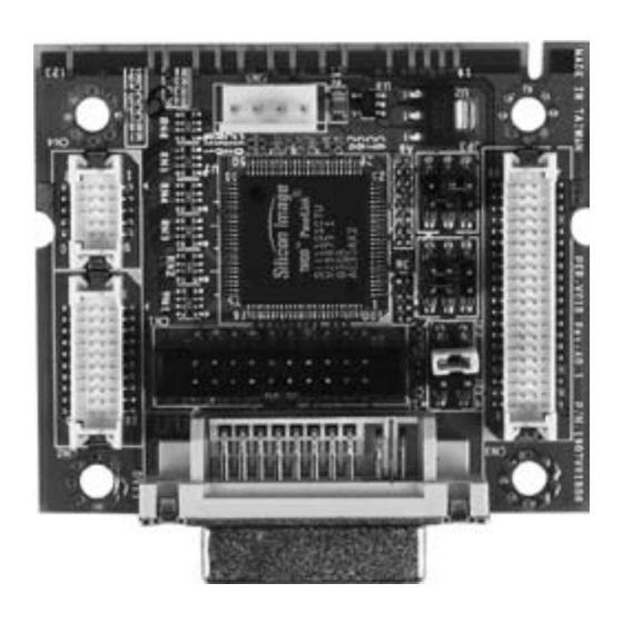
Page 8: Location Of Jumpers And Connectors
M i n i P C I D V I t o T T L M o d u l e P E R - V 0 1 B 1.3 Location of Jumpers and Connectors 1.4 Mechanical Drawing (10.86) (10.00) (5.40) (0.80) 53.40 46.86 46.86 46.12 37.21 36.16 15.36 14.03 11.07 1.01 0.00 0.00 6.35 (5.40) PER-V01B Quick Installation Guide... -
Page 9: List Of Jumpers
TTL_LCD DF13-40P Connector POWER Connector 1.7 ODCK Normal & Inverted Select (JP1) Label Function ODCK Inverted Output ODCK Normal Output (Default) 1.8 ST & STAG_OUT Select (JP2) Label Function High Output Drive Strength Low Output Drive Strength (Default) PER-V01B Quick Installation Guide... -
Page 10: Pixs & Hs_Jdtr Select (Jp3)
Two pixel per clock (for 36-bits) One pixel per clock (for 18/24-bits) (Default) HS_JDTR Label Function Enable the HSYNC de-jitter (Default) Disable the HSYNC de-jitter 1.10 DVI Internal Connector (DVI1) Signal Signal TX2- TX2+ DDC_CLK DDC_DATA TX1- TX1+ PER-V01B Quick Installation Guide... -
Page 11: Dvi External Connector (Cn1)
TX0+ TXC+ TXC- 1.11 DVI External Connector (CN1) Signal Signal DVI_TX1+ DVI_TX1- DVI_TXC+ DVI_TXC- HPDET DVI_TX2+ DVI_TX2- DVI_TX0+ DVI_TX0- DDC_DATA DDC_CLK 1.12 TTL_LCD DF13-40P Connector (CN3) Signal Signal +3.3V +3.3V E_BLUE0 E_BLUE1 E_BLUE2 E_BLUE3 E_BLUE4 E_BLUE5 PER-V01B Quick Installation Guide... -
Page 12: Ttl_Lcd Df13-20P Connector (Cn2)
E_RED0 E_RED1 E_RED2 E_RED3 E_RED4 E_RED5 E_RED6 E_RED7 ODCK VSYNC HSYNC 1.13 TTL_LCD DF13-20P Connector (CN2) Signal Signal O_BLUE2 O_BLUE3 O_BLUE4 O_BLUE5 O_BLUE6 O_BLUE7 O_GREEN2 O_GREEN3 O_GREEN4 O_GREEN5 O_GREEN6 O_GREEN7 O_RED2 O_RED3 O_RED4 O_RED5 O_RED6 O_RED7 PER-V01B Quick Installation Guide... -
Page 13: Power Connector (Cn5)
2. Connecting CN3 & CN2 for 18-bit, 24-bit, 36-bit LCD. 3. CN5 is not needed if plugging in Mini PCI slot. 4. Please use either DVI1 or CN1 for DVI output. DVI1 and CN1 cannot be used simultaneously. PER-V01B Quick Installation Guide...
Need help?
Do you have a question about the PER-V01B and is the answer not in the manual?
Questions and answers