
Related Manuals for Aaeon PFM-C20N


Summary of Contents for Aaeon PFM-C20N
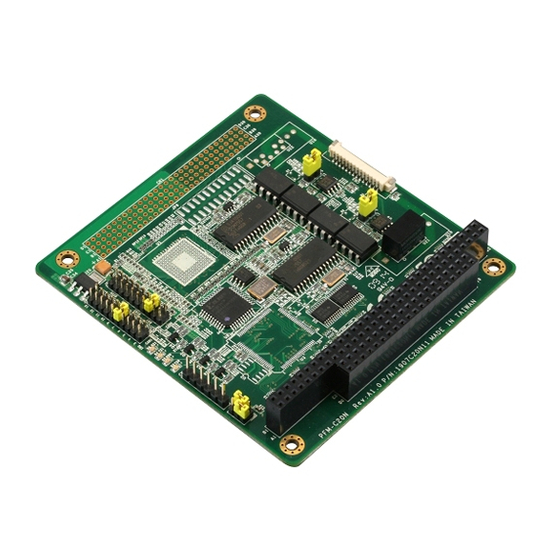
- Page 1 CAN Bus Module P F M - C 2 0 N PFM-C20N PC/104 CAN Bus Module SJA 1000 CAN Chipset CAN 2.0 Compatible Isolating Voltage Up to 1600VDC PFM-C20N Manual Rev.A 1st Ed. June 2009...
- Page 2 AAEON assumes no liabilities resulting from errors or omissions in this document, or from the use of the information contained herein. AAEON reserves the right to make changes in the product design without notice to its users.
- Page 3 CAN Bus Module P F M - C 2 0 N Acknowledgments All other products’ name or trademarks are properties of their respective owners. Award is a trademark of Award Software International, Inc. CompactFlash™ is a trademark of the Compact Flash Association.
- Page 4 CAN Bus Module P F M - C 2 0 N Packing List Before you begin installing your card, please make sure that the following materials have been shipped: Utility CD PFM-C20N...
-
Page 5: Table Of Contents
CAN Bus Module P F M - C 2 0 N Contents Chapter 1 General Information 1.1 Introduction ............1-2 1.2 Features ..............1-2 1.3 Specifications ............1-3 Chapter 2 Quick Installation Guide 2.1 Safety Precautions ..........2-2 2.2 Location of Connectors and Jumpers ......2-3 2.3 Mechanical Drawing ..........2-4 2.4 List of Jumpers ............2-5 2.5 List of Connectors ..........2-5... - Page 6 CAN Bus Module P F M - C 2 0 N 3.1 Testing with Windows XP ........3-2 3.2 Testing with Linux ..........3-9 Appendix A Mating Connector A.1 List of Mating Connectors and Cables ....A-2...
-
Page 7: Chapter 1 General Information
C AN B u s M o d u l e P F M - C 2 0 N Chapter General Information 1- 1 Chapter 1 General Information... -
Page 8: Introduction
The PFM-C20N features PC/104+ expansion interfaces. supports Windows XP and Linux operating systems. Moreover, it is CAN 2.0 compatible and up to 1Mbps. The PFM-C20N was designed to enhance benefit for the Subcompact and peripheral boards. -
Page 9: Specifications
C AN B u s M o d u l e P F M - C 2 0 N 1.3 Specifications Form Factor PC/104 & PCI-104 (90mm x 96mm) CAN Chipset SJA1000 Expansion Slot PC/104 or PCI-104 Power Requirement +3.3V and +5V Operating Temperature 32˚F~ 140˚F (0˚C ~ 60˚C) Isolation Voltage 1600V DC... -
Page 10: Chapter 2 Quick Installation Guide
C AN B u s M o d u l e P F M - C 2 0 N Chapter Quick Installation Guide Notice: The Quick Installation Guide is derived from Chapter 2 of user manual. For other chapters further installation instructions, please refer to the user manual CD-ROM that came with the... -
Page 11: Safety Precautions
C AN B u s M o d u l e P F M - C 2 0 N 2.1 Safety Precautions Always completely disconnect the power cord from your board whenever you are working on it. Do not make connections while the power is on, because a sudden rush of power can damage sensitive electronic components. -
Page 12: Location Of Connectors And Jumpers
C AN B u s M o d u l e P F M - C 2 0 N 2.2 Location of Connectors and Jumpers 2- 3 Chapter 2 Quick Installation Guide... -
Page 13: Mechanical Drawing
C AN B u s M o d u l e P F M - C 2 0 N 2.3 Mechanical Drawing 2 - 4 Chapter 2 Quick Installation Guide... -
Page 14: List Of Jumpers
C AN B u s M o d u l e P F M - C 2 0 N 2.4 List of Jumpers The board has a number of jumpers that allow you to configure your system to suit your application. The table below shows the function of each of the board's jumpers: Label Function... -
Page 15: Setting Jumpers
C AN B u s M o d u l e P F M - C 2 0 N 2.6 Setting Jumpers You configure your card to match the needs of your application by setting jumpers. A jumper is the simplest kind of electric switch. It consists of two metal pins and a small metal clip (often protected by a plastic cover) that slides over the pins to connect them. -
Page 16: Can Bus Port 1 Termination Resistor Setup (Jp1)
C AN B u s M o d u l e P F M - C 2 0 N 2.7 CAN BUS Port 1 Termination Resistor Setup (JP1) Function Termination Resistor Setup 2.8 Address Condition (JP2) Function 1-3,2-4 DC00 1-3,4-6 DB00 3-5,2-4 DA00 (Default) -
Page 17: Can Bus Port 2 Irq Setup (Jp5)
C AN B u s M o d u l e P F M - C 2 0 N 9-10 IRQ7 11-12 IRQ9 13-14 IRQ10 15-16 IRQ11 17-18 IRQ12 19-20 IRQ15 2.11 CAN BUS Port 2 IRQ Setup (JP5) Function IRQ3 IRQ4 IRQ5... -
Page 18: Pciclock & Arbitration Pins Setup (Jp6)
C AN B u s M o d u l e P F M - C 2 0 N 2.12 PCICLOCK & Arbitration Pins Setup (JP6) Function PCI_CLK0 (Default) PCI_CLK1 PCI_CLK2 PCI_CLK3 9-10 GNT#0 (Default) 11-12 GNT#1 13-14 GNT#2 15-16 GNT#3 17-18 REQ#0 (Default) - Page 19 C AN B u s M o d u l e P F M - C 2 0 N AD14 AD13 +3.3V C/BE1# SERR# PERR# STOP# +3.3V +3.3V TRDY# FRAME# AD16 AD18 +3.3V AD21 AD20 +3.3V AD23 IDSEL AD24 C/BE3# AD26 AD29 AD30...
- Page 20 C AN B u s M o d u l e P F M - C 2 0 N AD10 N.C. AD12 AD15 +3.3V N.C. +3.3V N.C. LOCK# DEVSEL# IRDY# +3.3V +3.3V C/BE2# AD17 AD19 AD22 +3.3V N.C. N.C. N.C. N.C.
-
Page 21: Cpld Jtag (Cn2)
C AN B u s M o d u l e P F M - C 2 0 N GNT#2 PCI_CLK1 PCI_CLK3 RST# INTB# N.C. GNT#3 Note: If PCI-104 Connector B1 is not SERIRQ signal, this card can not support IRQ mode. 2.14 CPLD JTAG (CN2) Signal CPLD_TMS... -
Page 22: Pc/104 Connector (Cn4) (Optional)
C AN B u s M o d u l e P F M - C 2 0 N CAN0L N.C. CAN1H CAN1L N.C. LED_TX0 LED_RX0 LED_TX1 LED_RX1 SERIRQ 2.16 PC/104 Connector (CN4) (Optional) Signal Signal N.C. RSTDRV IRQ9 2- 13 Chapter 2 Quick Installation Guide... - Page 23 C AN B u s M o d u l e P F M - C 2 0 N N.C. SMEMW# SA19 SMEMR# SA18 IOW# SA17 IOR# SA16 N.C. SA15 N.C. SA14 N.C. SA13 N.C. SA12 N.C. SA11 N.C. SA10 IRQ7 IRQ6 IRQ5...
- Page 24 C AN B u s M o d u l e P F M - C 2 0 N N.C. N.C. N.C. N.C. IRQ10 N.C. IRQ11 N.C. N.C. IRQ12 SA19 IRQ15 SA18 N.C. SA17 N.C. N.C. N.C. N.C. N.C. N.C. N.C.
- Page 25 C AN B u s M o d u l e P F M - C 2 0 N Below Table for China RoHS Requirements 产品中有毒有害物质或元素名称及含量 AAEON Main Board/ Daughter Board/ Backplane 有毒有害物质或元素 部件名称 铅 汞 镉 六价铬 多溴联苯 多溴二苯醚...
- Page 26 C AN B u s M o d u l e P F M - C 2 0 N Chapter Driver Installation 3 - 1 Chapter 3 Driver Installation...
-
Page 27: Testing With Windows Xp
C AN B u s M o d u l e P F M - C 2 0 N 3.1 Testing with Windows XP Step1: Open the “WinXP2” folder and click on “vcredist_x86.exe” to start installing VC2008 Redistributable. Click ”Next “ to continue. 3 - 2 Chapter 3 Driver Installation... - Page 28 C AN B u s M o d u l e P F M - C 2 0 N Check the check box and click on “Install” to follow the instruction until the computer shows to “Finish” 3 - 3 Chapter 3 Driver Installation...
- Page 29 C AN B u s M o d u l e P F M - C 2 0 N Step 2: Double click on the “Canbus.exe” file Step 3: Click on “Configuration ”, to setup setting. 3 - 4 Chapter 3 Driver Installation...
- Page 30 C AN B u s M o d u l e P F M - C 2 0 N The setting of Base Address has to be the same as Jumper setting. IRQ only support POLLING. The Baud Rates of Transmit Port and Monitor Port have to be the same.
- Page 31 C AN B u s M o d u l e P F M - C 2 0 N Step 4: The system will show the configuration information on “Port 0” and “Port 1” windows and detect the hardware status automatically.
- Page 32 C AN B u s M o d u l e P F M - C 2 0 N Step 5: Setup the “Monitor Port”: Please select “Port 0” or “Port 1” as the Monitor Port. After setting, the pop out will ask you if the setting is correct or not.
- Page 33 C AN B u s M o d u l e P F M - C 2 0 N checked.) can be keyed in “0~0x7ff.” The ID of Extended frame is “0~0x1fffffff.” (The Extended frame can be selectable in “Peli” Mode only.) For RTR, please key in “0”...
-
Page 34: Testing With Linux
Step 1: Please log in as “root” when you start the computer. (If you log in other identities, you have to command “sudo” to switch the identity, or you cannot insert/remove module. Below use Fedora5 as example (GENE-5315 + PFM-C20N PC-104) Step 2: Copy the Fedora5 folder (…/PFM-C20N/Linux/ISA/5315/FedoraCore5/Fedora5) to the root’s home. - Page 35 ※ If it does not show ”localhost.localdomain,” you have to continue to the following step 2-A. If it shows properly, please go to Step 3. 2-A: If you get the output is “aaeon.5315” for example, please command the following instructions.
- Page 36 C AN B u s M o d u l e P F M - C 2 0 N 3 - 11 Chapter 3 Driver Installation...
- Page 37 If it is DA00, you have to set “0xda000.” If it is DB00, you have to set “0xdb000.” irq_0: Setup interrupt, you may set “0” as polling mode. For choosing IRQ of PFM-C20N, please use the same settings of JP4 (PORT1) and JP5 (PORT2). If you set “0,” please get rid of the jumper.
- Page 38 C AN B u s M o d u l e P F M - C 2 0 N Baud_0: can set with 125,250,500,800 and 1000 AccMask_0: Default=0xffffffff (no need to change) AccCode_0: Default=0xffffffff (no need to change) Timeout_0: Default=10 (no need to change) Outc_0: Default=0xda (no need to change) VendOpt_0: Default=a (no need to change) IOModel_0: Default=m (no need to change)
- Page 39 C AN B u s M o d u l e P F M - C 2 0 N Command “grep” to check if the driver setting is the same or not. (you may skip this step) [root@localhost Fedora5]# grep . /proc/sys/Can/* Step 6: Start testing the transmission, you have to create a new terminal (File Open Terminal) on the existing terminal.
- Page 40 C AN B u s M o d u l e P F M - C 2 0 N The default Monitor Port is “can0”. You may use the following instruction to assign the Monitor Port to be “can1.” [root@localhost Fedora5]# ./receive can1 And then, use the other Terminal to transmit message.
- Page 41 C AN B u s M o d u l e P F M - C 2 0 N If you want to stop the Monitor Port to monitor data bus, just let the Terminal on focus and press ctrl+c to stop. If you did not stop receiving data via the Monitor Port, the resource of the port will be occupied.
- Page 42 C AN B u s M o d u l e P F M - C 2 0 N Step 8: Testing by using different platforms Using the two boards to test the transmitting and receiving. For example, the can0 of GENE-5315 is the Monitor Port, and the can0 of EPIC-8526 will be the Transmit Port.
- Page 43 C AN B u s M o d u l e P F M - C 2 0 N Appendix Mating Connecotor A - 1 Appendix A Mating Connector...
-
Page 44: A.1 List Of Mating Connectors And Cables
P F M - C 2 0 N A.1 List of Mating Connectors and Cables The table notes mating connectors and available cables. Connector Function Mating Connector Available Cable AAEON Cable Label Vendor Model no CATCH A003-678 CAN Cable 1703140150...
Need help?
Do you have a question about the PFM-C20N and is the answer not in the manual?
Questions and answers