Advertisement
Quick Links
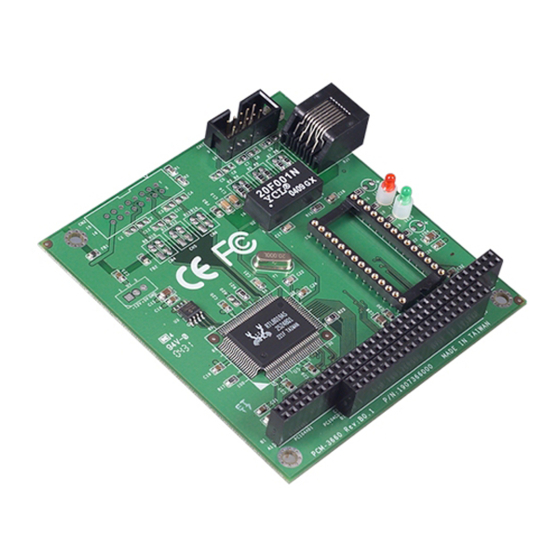
P C / 1 0 4 P e r i p h e r a l M o d u l e
Notice
This guide is designed for experienced users to setup the system in
the shortest time.
Safety Precautions
Always completely disconnect the power cord
from your board whenever you are working
on it. Do not make connections while the
power is on, because a sudden rush of power
can damage sensitive electronic
components.
Always ground yourself to remove any static
charge before touching the board. Modern
electronic devices are very sensitive to static
electric charges. Use a grounding wrist strap
at all times. Place all electronic components
on a static-dissipative surface or in a
static-shielded bag when they are not in the
chassis.
PCM-3660 Rev.B Quick Installation Guide
P C M - 3 6 6 0 R e v . B
1-1
Advertisement

Related Manuals for Aaeon PCM-3660 Rev.B


Summary of Contents for Aaeon PCM-3660 Rev.B
- Page 1 Use a grounding wrist strap at all times. Place all electronic components on a static-dissipative surface or in a static-shielded bag when they are not in the chassis. PCM-3660 Rev.B Quick Installation Guide...
- Page 2 PC/104 connector on your CPU card or PC/104 CPU module. The module automatically senses whether it is connected to an 8-bit or 16-bit PC/104 system. The PCM-3660 Rev.B fully complies with IEEE 802.3 10 Mbps CSMA/CD standards and is 100% Novell NE2000 compatible.
- Page 3 Built-in 10BASE-T transceiver for unshielded twisted pair cabling up to 100 meters Two diagnostic LEDs indicate network status Onboard 32K memory for high-performance multi-package buffer Software drivers for most popular network environments PCM-3660 Rev.B Quick Installation Guide...
- Page 4 3.5” x 3.8” (90mm x 96 mm ) Software -Lantasti 4.x/5.xdriver Driver Support -NDIS 2.x driver -Packet driver -SCO UNIX driver -Netware ODI driver -NDIS 3.0 miniport driver for Windows NT 31, Windows NT 35 and Windows 95 -OS2driver PCM-3660 Rev.B Quick Installation Guide...
- Page 5 10BASE-2, 10BASE-5 and 10BASE-FOIRL by external transceiver General Power +5 V 400 mA max. Operating 32°F~140°F (0°C ~ 60°C) Temperature Storage 5°F~176°F (-15°C ~ 80°C) Temperature Humidity 10% ~ 90% PCM-3660 Rev.B Quick Installation Guide...
- Page 6 P C M - 3 6 6 0 R e v . B Installation Your package should contain the following items. If they are missing, damaged or fail to meet specifications, contact your dealer/sales representative immediately. PCM-3660 Rev.B Drivers PCM-3660 Rev.B Quick Installation Guide...
- Page 7 If by chance the EEPROM becomes corrupted, the PG8019.EXE program allows you to reconfigure the card. 3. 8019AS.CFG When you run PG801 9.EXE, it will read the configuration parameters stored in this file. PCM-3660 Rev.B Quick Installation Guide...
- Page 8 PNP mode configuration. To execute the configuration, to see the current configuration, or run diagnostics as followings: 1. Power the PCM-3660 Rev.B on. Make sure that the RSET8019.EXE file is located in a working directory. PCM-3660 Rev.B Quick Installation Guide...
- Page 9 1. Run EEPROM test. 2. Run Diagnostics on Board. 3. Run Diagnostics on Network Each option has its own display screen which shows the format and result of any diagnostic tests undertaken. Remote boot ROM (P/N: PCL-843-ROM) PCM-3660 Rev.B Quick Installation Guide...
- Page 10 Install the boot ROM as shown below. Make sure that you align the notch on the ROM chip with the notch on the socket. 1-10 PCM-3660 Rev.B Quick Installation Guide...
- Page 11 P C M - 3 6 6 0 R e v . B Hardware Installation The following instructions show how to install the PCM-3660 Rev.B module on a CPU card. The process is similar to PC/104 CPU modules’ and see the figures.
- Page 12 8. Reinstall the CPU card and system unit cover. Reconnect the cables you removed in step 2. Turn on the power. This completes the hardware installation. Install the software drivers according to the instructions of your operating system. 1-12 PCM-3660 Rev.B Quick Installation Guide...
- Page 13 185m (607 ft.) thin (RG-58) max. 10 Base-5 10 Mbps 50 Ohm Ethernet 500m (1640 ft.) thin (RG-11) max. 10 Base-T 10 Mbps Star 100 Ohm 100m (328 ft.) unshielded twisty max. pair Pin Assignment (CN2) 1-13 PCM-3660 Rev.B Quick Installation Guide...
- Page 14 Data reception positive Data reception negative LCD Indicators The module’s two LED indicators show the status of the communication link and traffic. Flashing LED2 Traffic No traffic LED3 Link OK Link failure RJ-45 Pin assignments 1-14 PCM-3660 Rev.B Quick Installation Guide...
Need help?
Do you have a question about the PCM-3660 Rev.B and is the answer not in the manual?
Questions and answers