Sign In
Upload
Manuals
Brands
Aaeon Manuals
Control Unit
PCM-5335
Aaeon PCM-5335 Manuals
Manuals and User Guides for Aaeon PCM-5335. We have
2
Aaeon PCM-5335 manuals available for free PDF download: Manual
Aaeon PCM-5335 Manual (94 pages)
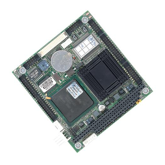
All In One NS Geode GX1 with SVGA/LCD/Ethernet Interface PC/104 CPU Module
Brand:
Aaeon
| Category:
Computer Hardware
| Size: 2.96 MB
Table of Contents
Table of Contents
4
Chapter 1 General Information
11
Introduction
12
Features
13
Specifications
14
Standard SBC Functions
14
VGA Function
14
Ethernet Function
15
Solid State Disk
15
Mechanical and Environmental
15
Board Dimensions
16
Figure 1-1: PCM-5335 Dimensions
16
Chapter 2 Installation
17
Connectors
18
Table 2-1: Connectors
18
Locating Connectors
19
Figure 2-1: Locating Connectors (Component Side)
19
Figure 2-2: Locating Connectors (Solder Side)
19
Safety Precautions
20
Ethernet Connector (CN1)
20
Network Boot
20
LCD Display Connector (CN2)
20
Serial Ports
21
(Cn3: Com1; Cn4: Com2/Rs-232; Cn18: Com2/Rs-422/485)
21
RS-232 Connection (COM1: CN3)
21
RS-232/422/485 Connection (COM2: CN4: RS-232; CN18: RS-422/485)
21
Table 2-2: Serial Port Connections (COM1, COM2)
21
EIDE HDD Connector (CN5)
22
Connecting the Hard Drive
22
PC/104 Connector (CN6)
22
Table 2-3: Serial Port Default Settings
22
Parallel Port Connector (CN7)
23
Backlight Connector (CN8)
23
VGA Connector (CN9)
23
CRT Display Connector (CN9)
23
Main Power (+5 V / +12 V) Connector (CN11)
23
PS/2 Keyboard/Mouse Connector (CN12)
24
FDD Connector (CN14)
24
Connecting the Floppy Drive
24
Compactflash™ Socket (CN16)
25
USB Connector (CN17)
25
Multifunction Jumpers (MJ1)
26
Auxilary Power Connector (MJ1-A)
26
Fan Connector (MJ1-B)
27
Reset Button Connector (MJ1-C)
27
IR Connector (MJ1-D)
27
Watchdog Timer Configuration (MJ1-E)
27
SO DIMM Socket (Slot1)
28
Installing Sodimms
28
Chapter 3 Software Configuration
31
Introduction
32
Utility CD Disk
32
VGA Display Software Configuration
32
Figure 3-1: Contents of the PCM-5335 Series Utility Disk
32
Figure 3-2: BIOS VGA Setup Screen
33
Connections for Two Standard Lcds
34
Connections for Toshiba LTM10C042
34
Color LCD)
34
Connections for Toshiba LTM12C275A (800 X 600 TFT Color LCD)
35
Chapter 4 Award BIOS Setup
37
System Test and Initialization
38
System Configuration Verification
38
Award BIOS Setup
39
Entering Setup
39
Figure 4-1: BIOS Setup Program Initial Screen
39
Standard CMOS Setup
40
Figure 4-2: CMOS Setup Screen
40
BIOS Features Setup
41
Figure 4-3: BIOS Features Setup
41
Chipset Features Setup
42
Figure 4-4: Chipset Features Setup
42
Power Management Setup
43
Figure 4-5: Power Management Setup
43
Pnp/Pci Configuration
44
Figure 4-6: Pnp/Pci Configuration
44
Integrated Peripherals
45
Figure 4-7: Integrated Peripherals
45
Change Password
46
Save & Exit Setup
47
Exit Without Saving
47
Chapter 5 PCI Bus Ethernet Interface
49
Introduction
50
Installation of Ethernet Driver
50
Installation for Windows 98/2000
51
Further Information
54
Chapter 6 SVGA Setup
55
Introduction
56
Chipset
56
Display Memory
56
Installation of SVGA Driver
56
Installation for Cyrix Mediagx Certified Drivers for Windows 95/98. Insert the Disk into the CD-ROM Drive
57
Installation for Windows NT
61
Further Information
66
Appendix A Programming the Watchdog Timer
67
Programming the Watchdog Timer
68
Appendix B Installing PC/104 Modules
71
Installing PC/104 Modules
72
Figure B-1: PC/104 Module Mounting Diagram
73
Figure B-2: PC/104 Module Dimensions (MM) (±0.1)
73
Table B-1: PCM-5335 PC/104 Connectors (CN6)
74
Appendix C Pin Assignments
75
Ethernet Connector (CN1)
76
Table C-1: Ethernet Connector (CN1)
76
LCD Connector (CN2)
77
Table C-2: LCD Connector (CN2)
77
COM1 Connector (CN3)
78
COM2 Connector (CN4)
78
Table C-3: COM1 Connector (CN3)
78
Table C-4: COM2 Connector (CN4)
78
EIDE Hard Drive Connector (CN5)
79
Table C-5: EIDE Hard Drive Connector (CN5)
79
PC/104 Connector (CN6)
80
Parallel Port Connector (CN7)
80
Table C-7: Parallel Port Connector (CN7)
80
Backlight Connector (CN8)
81
VGA Connector (CN9)
81
Table C-9: VGA Connector (CN11)
81
Table C-8: Backlight Connector (CN8)
81
Main Power (+5 V) Connector (CN11)
82
PS/2 Keyboard/Mouse Connector (CN12)
82
Table C-10: Main Power (+5 V) Connector (CN11)
82
Table C-11: PS/2 Keyboard/Mouse Connector (CN12)
82
FDD Connector (CN14)
83
Table C-12: FDD Connector (CN14)
83
Compactflash™ Socket (CN16)
84
Table C-13: Compactflash™ Socket (CN16)
84
Figure C-1: Compactflash™ Socket
85
COM2 Connector for 422/485 (CN18)
86
Multifunction Jumpter (MJ1)
86
Table C-14: COM2 Connector for 422/485 (CN18)
86
Table C-15: MJ1-A, -5 V, -12 V Input
86
Table C-16: MJ1-B, Fan Connector
86
Table C-18: MJ1-D, IR Connector
87
Table C-19: MJ1-E, Watchdog Jumper
87
Table C-17: MJ1-C, Reset Button
87
Appendix D System Assignments
89
System I/O Ports
90
Table D-1: System I/O Ports
90
DMA Channel Assignments
91
Table D-2: DMA Channel Assignments
91
Interrupt Assignments
92
Table D-3: Interrupt Assignments
92
1St MB Memory Map
93
Table D-4: 1St MB Memory Map
93
Advertisement
Aaeon PCM-5335 Manual (60 pages)
All In One NS Geode GX1 with SVGA/ LCD/ Ethernet Interface PC/ 104 CPU Module
Brand:
Aaeon
| Category:
Control Unit
| Size: 0.7 MB
Table of Contents
Table of Contents
5
Chapter 1 General Information
7
Introduction
8
Features
9
Specifications
10
Chapter 2 Quick Installation Guide
13
Safety Precautions
13
Location of Connectors and Jumpers
14
Mechanical Drawing
16
List of Jumpers
18
List of Connectors
19
Jumper Setting
20
Clear CMOS (JP1)
21
LCD Clock Selection (JP2)
21
COM2 RS-232/422/485 Selection (JP3, JP5)
21
LCD Voltage Selection (JP4)
22
Front Panel Connector (CN1)
22
External Power Connector (CN2)
23
PC/104 Connector (CN3)
24
Keyboard/ Mouse Connector (CN4)
25
PC/104 Connector (CN5)
26
USB Connector (CN6)
28
VGA Connector (CN7)
29
Parallel Port Connector (CN8)
30
IDE Connector (CN9)
31
COM1 RS-232 Connector (CN10)
33
Floppy Connector (CN11)
34
TTL LCD Connector (CN13)
37
10/100Base-T Ethernet Connector (CN14)
38
Main Power Connector (CN15)
38
Compactflash Socket (CN16)
39
Chapter 3 Award BIOS Setup
41
Award BIOS Setup
41
Chapter 4 Driver Installation
51
Installation 1
51
Installation 2
52
Installation 3
53
Appendix A Programming the Watchdog Timer
55
Advertisement
Related Products
Aaeon PCM-8152
Aaeon PCM-3536
Aaeon PCM-3660 Rev.B
Aaeon PER-C10L
Aaeon PICO-BSW1
Aaeon PER-C20L
Aaeon PFM-530I
Aaeon PFM-800P
Aaeon PFM-C20N
Aaeon PER-C38L
Aaeon Categories
Motherboard
Computer Hardware
Desktop
Touch Panel
Control Unit
More Aaeon Manuals
Login
Sign In
OR
Sign in with Facebook
Sign in with Google
Upload manual
Upload from disk
Upload from URL