
Related Manuals for Samwontech TEMP2000 Series


Summary of Contents for Samwontech TEMP2000 Series
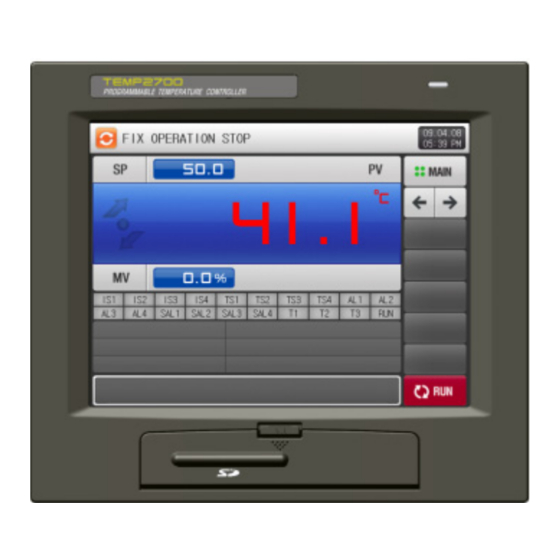
- Page 1 TEMP2000 - SERIES TEMP2700 TEMP2500 TEMP2300 INSTALLATION MANUAL Programmable Controller...
-
Page 2: Table Of Contents
SAMWONTECH ※ This manual applies to TEMP2300, TEMP2500 and TEMP2700. ※ The model stated the manual content is TEMP2500. Contents Safety Precautions Package checklist …………………………………………………………………………………………… Dimension & Installation …………………………………………………………………………………·· Wiring ………………………………………………………………………………………………………… Display Unit description …………………………………………………………………………………·· Control Unit LED description ……………………………………………………………………………··... - Page 3 SAMWONTECH ALARM SIGNAL Alarm Signal setting ………………………………………………………………………………………… Alarm Signal operation ……………………………………………………………………………………·· 10. PID GROUP 10.1 PID Range setting …………………………………………………………………………………………·· 10.2 PID Group setting …………………………………………………………………………………………·· 11. DIGITAL INPUT (DI) CONFIGURATION 11.1 DI Operation setting ………………………………………………………………………………………… 11.2 DI Error Name setting ………………………………………………………………………………………·...
-
Page 4: Safety Precautions
(B) Read and understand this Installation Manual carefully before using the product. (C) This Installation Manual describes functions and features of the product in detail, and SAMWONTECH can not guarantee against over applications would suit a customer’s particular purpose which is not described in this manual. - Page 5 (A) SAMWONTECH does not guarantee or accept responsibility for this product other than the clauses stated in our warranty policy. (B) SAMWONTECH assumes no liability to any party for any loss or damage, direct or indirect, caused by the use or any unpredictable defect of the product.
-
Page 6: Package Checklist
SAMWONTECH 1.1 Package Checkpoint ▶ Please check any damage to the product by inspecting the appearance of the delivered product first. In addition, check the following items. 1.1.1 Verify the model suffix code ▶ Check to see if specifications of the delivered product are the same as those of your order. - Page 7 SAMWONTECH 1.1.3 How to Handle Any Damaged Product ▶ Contact your product supplier or our sales representative for assistance in case of any damage to the product or any missing parts as a result of check in the appearance of products as described above.
-
Page 8: Dimension & Installation
SAMWONTECH 1.2 Dimension and Installation 1.2.1 Environments for Installation 음Caution for installation location and environment (A) Be sure to power on and operate the controller after installation on a panel to prevent electric shock. (B) Do not install the controller at following places or environment. - Page 9 SAMWONTECH 1.2.2 External Dimension (Unit : mm) 1.2.2.1 External Dimension of Display Unit according to each Model Unit : mm Model TEMP2300 33.5 97.5 104.5 TEMP2500 33.5 136.5 136.5 TEMP2700 38.2 172.5 195.5 1.2.2.2 External Dimension of Control Unit 100.8 2nd Edition of TEMP2000_Series IM : July.
- Page 10 SAMWONTECH 1.2.2.3 External Dimension of I/O1 BOARD 1.2.2.4 External Dimension of I/O2 BOARD 1.2.3 PANEL CUTOUTS ▶ Normal Panel Cutting +1.0 ※ Panel Cutouts Unit : mm Model TEMP2300 TEMP2500 250(MIN) TEMP2700 2nd Edition of TEMP2000_Series IM : July. 16. 2010...
- Page 11 SAMWONTECH 1.2.4 MOUNT Installation 1.2.4.1 표시부 설치방법 ▶ DISPLAY UNIT Mount Fixture Screwdriver Direction Panel Thickness: 2~7mm DISPLAY UNIT Panel (Refer to 1.2.3 PANEL CUTOUTS) ▶ TEMP2500/2700 Display Unit Panel Installation Method Fixture Screwdriver Direction Panel Thickness: DISPLAY 2~7mm Fix mount may be mounted...
- Page 12 SAMWONTECH ▶ VESA Mount installation ☞ 75*75, VESA standard size applies to all TEMP2000 series. VESA Standard (75*75) ※Required bolt for jointing VESA HOLE is M4*4L ~ 6L 1.2.4.2 CONTROL UNIT Mount ▶ DIN RAIL Mount Required DIN RAIL Dimension...
- Page 13 SAMWONTECH ▶ Mounting on surface of the wall Required screw torque : 0.3N.m(3Kgf.m) M3*12 BACK COVER 25.56 ⓐ Push ⓑ Pull down * External Hole dimension Control ☞ Detach the BACK COVER by pulling down ⓑ part from main body, while pushing ⓐ part.
-
Page 14: Wiring
SAMWONTECH 1.3 Wiring Precaution ▶ Switch off the main power supply and make sure that no current flows in all the circuits before the wiring work. ▶ Do not touch the real terminal part while the power is on. ▶ Main circuit breaker must be kept in OFF state until all the wiring work is done. - Page 15 SAMWONTECH 1.3.2 Terminal Assignment 1.3.2.1 TEMP2300 DISPLAY UNIT Terminals Power(DC24V) COM1 DISPLAY and CONTROL COM2 DISPLAY and PC 1.3.2.2 TEMP2500/2700 DISPLAY UNIT Terminals Power(DC24V) COM1 DISPLAY and CONTROL COM2 DISPLAY and PC 2nd Edition of TEMP2000_Series IM : July. 16. 2010...
- Page 16 SAMWONTECH 1.3.2.3 CONTROL UNIT Terminals COM1 DISPLAY and CONTROL COM2 CONTROL and PC SCR1 COM3 CONTROL and I/O1 SCR2 Temperatur sensor SSR1 SSR2 Power(DC24V) COM4 SYNC COM 1.3.2.4 4 I/O1 BOARD Terminals Power(DC24V) I/O2 LINK COM. DI10 DI10 DI12 DI13...
- Page 17 SAMWONTECH 1.3.2.5 I/O2 BOARD Terminals RLY27 RLY28 RLY29 RLY30 RLY31 RLY32 I/O2 LINK RLY26 RLY25 RLY24 RLY23 RLY22 RLY21 RLY20 RLY19 RLY18 RLY17 RLY16 RLY15 RLY14 RLY13 2nd Edition of TEMP2000_Series IM : July. 16. 2010 Page 14 / 87...
- Page 18 SAMWONTECH 1.3.3 Power source wiring ▶ For power source wiring, use a vinyl-insulated wire (KSC 3304 or better). ① TEMP2300 Wiring ☞ Power wiring Wiring the cable to Power Socket (Make sure the +, - direction) Small (-) Screwdriver Make...
- Page 19 SAMWONTECH ☞ Wiring diagram of TEMP2300 with other UNITs COMM.CABLE(MP0310AS) DC24V(+) DC24V(-) COMM.CABLE(MP0310AS) I/O BOARD DC24V(+) DC24V(-) SMPS(Sepated Sales) AC220V ② TEMP2500/2700 Wiring COMM.CABLE(MP0310AS) DC24V(+) DC24V(-) COMM.CABLE(MP0310AS) I/O BOARD DC24V(+) DC24V(-) SMPS(Sepated Sales) AC220V 2nd Edition of TEMP2000_Series IM : July. 16. 2010...
- Page 20 SAMWONTECH ③ CONTROL UNIT Power Wiring DC24V 1.3.3.1 ANALOG INPUT Wiring ▶ Be careful of the polarity of the signal. The wrong connection may cause a trouble. ▶ Use a shielded wire for analog input and the shield should be 1-point grounded.
- Page 21 SAMWONTECH 1.3.3.2 ANALOG OUTPUT ▶ Be careful of the polarity. The wrong wiring may cause a trouble in the product. ▶ Use a shielded wire for analog input and the shield should be 1-point grounded. (가) Voltage Pulse Output(SSR) – SSR1 and SSR2 Analog Output Wiring is same.
- Page 22 SAMWONTECH 1.3.3.3 RELAY Wiring ▶ Make sure POWER OFF before wiring DO REALY. ▶ RELAY rating : Normal Open 30VDC 1A max, 250VAC 1A max. 30V DC 1A Max, 250V AC 1A Max 30V DC 1A Max, 250V AC 1A Max...
- Page 23 SAMWONTECH 1.3.3.5 Auxiliary RELAY ▶ If the wattage of the load is greater than the rating of output relay, an auxiliary relay should be used to on/off power on the load. ▶ When an inductive switch as a relay and a solenoid valve is used, it may be a noise source. A protective circuit should be installed to suppress a surge.
- Page 24 SAMWONTECH 1.3.3.6 TEMP2300 DISPLAY UNIT Communication wiring 30 ~ 40 mm 1.3.3.7 TEMP2500/2700 DISPLAY UNIT Communication wiring 15 ~ 20 mm 2nd Edition of TEMP2000_Series IM : July. 16. 2010 Page 21 / 87...
-
Page 25: Display Unit Description
SAMWONTECH 1.4 DISPLAY UNIT description ▶ TEMP2300 DISPLAY UNIT ③ ④ ① ⑤ ② ① Touch Pen fixing lever ② SD CARD port ③ LED lamp (Turning on yellow lamp when supplying power) ④ Touch screen ⑤ Touch Pen (will be spring out by pressing fixing lever right side) ▶... -
Page 26: Control Unit Led Description
SAMWONTECH 1.5 제어부 LED ▶ COM1 LED activates while connecting DISPLAY and CONTROL UNIT. ▶ COM2 LED activates while connecting CONTROL UNIT and PC. ▶ COM3 LED activates while connecting CONTROL UNIT and I/O 1 board. ▶ COM4 LED blinks for SYNC communication. -
Page 27: System Setting Configuration
SAMWONTECH 2. SYSTEM SETTING CONFIGURATION 2.1 MAIN MENU Screen ▶ This product consists of Touch Screen type LCD screen. ▶ Refer to [2.1 Initial operation flow] in [Operation Manual]. ▶ Below describes MAIN MENU screen and how to enter into SYSTEM PARAMETER SET screen. - Page 28 SAMWONTECH ▶ System Parameter Set Screen is as follows: [Figure 2-3] System Parameter Set Screen SYMBOL Item Description Remarks Input sensor concerned parameter group such as INPUT SET Chapter 3.1 sensor type and its range, and bias offset. Control & Retransmisstion Output setting parameter OUTPUT SET Chapter 4.1...
-
Page 29: System Parameter Setting Sequence
SAMWONTECH 2.2 SYSTEM PARAMETER Setting sequence ▶ Initial System Parameter Setup Sequence during equipment installation is as follows: Sequence SYMBOL Item Parameter in priority ① Set Temperature Sensor Type INPUT SET ② Set Sensor Range ③ Set other Parameter ① Set Output Type ② Set Output direction OUTPUT SET ③... -
Page 30: Input Set
SAMWONTECH 3. INPUT SET 3.1 Sensor Input setting 3.1.1 Sensor Input Screen-1 ▶ Select Temperature (T/C, RTD, DCV) Sensor. ☞ Sensor shall be selected first. ⑤ ① ⑥ ⑦ ② ⑧ ⑨ ③ ⑩ ④ ⑪ [Figure 3-1] Sensor Input Set Screen-1(T/C) ①... - Page 31 SAMWONTECH [Figure 3-2] Sensor Type Setup Screen(T/C) [Figure 3-3] Display Unit Setup Screen(T/C, RTD) ▶ Following screen is displayed when temperature sensor is set to RTD. [Figure 3-4] Sensor Input Setup Screen-1(RTD) 2nd Edition of TEMP2000_Series IM : July. 16. 2010...
- Page 32 SAMWONTECH ▶ Can select one from 6 types. [Figure 3-5] Sensor Type Selection Screen(RTD) ▶ Following screen is displayed when temperature sensor is set to DCV. ② ① Figure 3-6] Sensor Input Set Screen-1(DCV) ① Set floating point number. ② SCALE High/Low: Set Temperature Range.
- Page 33 SAMWONTECH ▶ Can select one sensor from 5 Sensor Types. [Figure 3-7] Sensor Type Selection Screen(DCV) ▶ Can select one unit from 12 units. [Figure 3-8] Display Unit Setup Screen(DCV) 2nd Edition of TEMP2000_Series IM : July. 16. 2010 Page 30 / 87...
- Page 34 SAMWONTECH ▶ This screen shows floating point selection. [Figure 3-9] Floating Point Setup (DCV) Table 3-1 Sensor Input Setup Screen-1 Parameter Parameter Range Unit Default Sensor Group T/C, RTD, DCV TC-K1, TC-K2, TC-J, TC-E, TC-T, TC-R, TC-B, TC-S, TC-L, TC-K2...
- Page 35 SAMWONTECH 3.1.2 Sensor Input Screen-2 ▶ Input compensation for temperature range. ▶ Compensation range is implemented as linear equation type between the compensation points. ④ ① ② ③ [Figure 3-10] Sensor Input Setup Screen-2 ① Set temperature input compensation. ② Set each base temperature point which requires compensation.
-
Page 36: Piece Bias Setting
SAMWONTECH 3.2 PIECE BIAS setting ▶ It displays Section Input Compensation. Input Comp. 8 Input Comp. 7 Input Comp. 6 Input Comp. 5 Input Comp. 4 Input Comp. 3 Input Comp. 2 Input Comp. 1 Actual Sensor Compensated Temperature Temperature Input Comp. - Page 37 SAMWONTECH ⑤ Compensated Temperature between Input Comp. 4 ~ Input Comp. 5 Section = Actual Sensor Temperature + (Actual Sensor Temperature – Input Comp. Point 4) X (Input Comp. 5 Value – Input Comp. 4 Value) + Input Comp. 4 Value (Input Comp.
-
Page 38: Control & Retransmission Output
SAMWONTECH 4. CONTROL & RETRANSMISSION OUTPUT 4.1 Control Output setting 4.1.1 Output Set Screen-1 ▶ Setup Output Types for Temperature Control. ▶ Following is the screen to check/setup the product setup in graphic. ③ ④ ① ② ⑤ [Figure 4-1] Output Set Screen-1 ①... - Page 39 SAMWONTECH [Figure 4-3] SCR Output Terminal & Retransmission Terminal Setup Table 4-1 Output Setup Screen-1 Parameter Parameter Range Unit Default SSR1 Output HEAT, UNUSE HEAT SSR2 Output HEAT, UNUSE UNUSE SCR1 Output Heat, RET., AUX., UNUSE RET. SCR2 Output Heat, RET., AUX., UNUSE UNUSE 2nd Edition of TEMP2000_Series IM : July.
-
Page 40: Retransmission Output Setting
SAMWONTECH 4.2 Retransmission Output Setup 4.2.1 Output Setup Screen-2 ⑥ ① ⑦ ② ③ ④ ⑤ ⑧ [Figure 4-4] Output Setup Screen-2 ① Set PID control operation method. ☞ Refer to [4.2.1.1 Operation Direction] ② Set Cycle Time for control output operation when control output is “SSR(SOLID STATE RELAY)”. - Page 41 SAMWONTECH 4.2.1.1 Operation Direction Control Output (MV) 100% Reverse Forward Control Output increase when PV is smaller Control Output increase when PV is bigger than SP. → Heating, Humidify than SP. → Cooling, Dehumidify Deviation(PV-SP) 4.2.1.2 Output Cycle ▶ Applies only when control output type is “SSR(Solid State Relay)”.
- Page 42 SAMWONTECH 4.2.1.3 Over-Integral Prevention ▶ It is one of efficient method to control when disturbance occurs. ☞ This function suppresses overshoot due to over-integral when control output reaches to max value. ▶ It does not work when I=0 at PID set value.
- Page 43 SAMWONTECH ◈ Example What is the P BAND when Input Range High(RH)= 100.0℃, Input Range Low (RL)= -100.0℃, Rate(P) = 10.0%, Over-Integral Prevent(ARW)= 200%? Answer) ① Input Range = RH – RL = 100.0℃ - (-100.0℃) = 200.0 ℃ ② Input Range x Rate(P) = 200.0℃ X 10.0% = 20.0℃...
-
Page 44: Output Terminals Displays / Settings
SAMWONTECH 4.3 Output Terminals displays / settings 4.3.1 Output Setup Screen-3 ▶ This screen is to set Retransmission. ▶ Retransmission can be set by selecting one from PV, SP, MV. ① ② [Figure 4-5] Retransmission Set Screen-3(PV, SP) ① Set Retransmission Type. - Page 45 SAMWONTECH 4.3.2 Output by Retransmission Type ▶ Retransmission Output is 4~20mA. ▶ Attach 250Ω(Precision Resistor) between both Retransmission terminal when use 1~5V retransmission output. ☞ When Retransmission Type is “PV” or “SP” 4.0mA 12.0mA 20.0mA Range Low Range High (Range High+Range Low)/2 ☞...
-
Page 46: Digital Output (Do) Configuration
SAMWONTECH 5. DIGITAL OUTPUT (DO) CONFIGURATION 5.1 DO parameters & RELAY number setting ▶ Set corresponding Relay No. to output when operation status is output to I/O Relay Board. ▶ Relay No. 13 ~ 32 can be used when I/O2 BOARD option is added. - Page 47 SAMWONTECH 5.1.2 Alarm Signal/Seg Alarm Signal Relay Setup Screen ① ② [Figure 5-2] Alarm Signal/Seg Alarm Signal Relay Setup Screen ① Set Alarm Signal Relay. (AL1∼AL4) ② Set Seg Alarm Signal Relay. (SEG AL1∼SEG AL4) Table 5-2 Alarm Signal/Seg Alarm Signal Relay Setup Screen Parameter...
- Page 48 SAMWONTECH 5.1.3 ON/OFF Signal Relay Setup Screen ▶ This set Relay Number for ON/OFF Signal, and Delay Time for each ON/OFF Signal. ▶ The preset ON/OFF Signal sends actual contact output when the signaling condition is met after preset Delay Time.
- Page 49 SAMWONTECH 5.1.4 DI Signal Relay Setup Screen ▶ This set Relay Number for DI Signal. ▶ DI Signal sends contact output to setup relay when DI error of corresponding number occurs. ① [Figure 5-4] DI Signal Relay Setup Screen ① Set DI Signal Relay. (DI1~DI16) ☞...
- Page 50 SAMWONTECH 5.1.5 Aux. Relay Setup Screen ▶ Following is Aux. Relay Setup Screen. ① ② ③ ④ [Figure 5-5] Aux. Relay Setup Screen-1 ① Set Run Signal Relay and Delay Time. ☞ Assigned Relay becomes “ON” after preset Delay Time.
- Page 51 SAMWONTECH ▶ Following is the setup items. ① ② ③ ④ [Figure 5-6] Aux Relay Setup Screen-2 ⑤ [Figure 5-7] Aux Relay Setup Screen-3 ① Set Up, Down Signal Relay and Operating Deviation. ☞ Status Lamp and Relay run same way at Run Screen.
- Page 52 SAMWONTECH Table 5-6 Aux. Relay Setup Screen-2, 3 Parameter Parameter Range Unit Default Up Signal Relay 0~32 Up Signal Deviation EUS(0.0~10.0%) EUS(0.0%) Soak Signal Relay 0~32 Signal Keep Time 0.00~99.59 (MIN.SEC) 00.00 Down Signal Relay 0~32 Down Signal Deviation EUS(0.0~10.0%) EUS(0.0%)
-
Page 53: Up, Soak, Down Signal Operation
SAMWONTECH 5.2 UP, SOAK, DOWN Signal Operation ▶ Input Sensor = Temperature(K2), Range = -200.00℃ ~ 1370.00℃ ▶ Up, Down Signal Range → [EUS 0% ~ EUS 10% ] = [ 0.00 ℃ ~ 20.00 ℃ ] Setup Up, Soak, Down Relay Operation according to Set Value... -
Page 54: Communication
SAMWONTECH 6. COMMUNICATION 6.1 Communication Interface Setting ▶ Remove Back Cover from [Figure 6-1 Control Unit], and setup communication method of RS-232C or RS-485 by changing socket located at Power Board. ▶ During Communication Setup form [Figure 6-2 Communication Setup], insert the socket to the pin header using tweezers (or other tools). -
Page 55: Communication Configuration
SAMWONTECH 6.2 Communication Configuration 6.2.1 Communication Setup Screen-1 ▶ This sets Communication Protocol and Communication Condition. ① ⑥ ② ⑦ ③ ④ ⑤ [Figure 6-3] Communication Setup Screen-1/1 ① Set Communication Protocol. ② Set Communication Speed. ☞ Refer to [Figure 6-4 Communication Setup Screen-1/2] ③... - Page 56 SAMWONTECH [Figure 6-4] Communication Setup Screen-1/2 Table 6-1 Communication Setup Screen-1 Parameter Parameter Range Unit Default PROTOCOL PC LINK, PC LINK + SUM, PC LINK + SUM MODBUS ASC, MODBUS RTU BAUD RATE 9600, 19200, 38400, 57600, 115200 9600 STOP BIT...
- Page 57 SAMWONTECH 6.2.1 Communication Setup Screen-2 ▶ This is to select required items for SYNC Communication. ① ② [Figure 6-5] Communication Setup Screen-2/1 ① Set Communication Speed for SYNC Communication. ② Set SYNC Master. [Figure 6-6] Communication Setup Screen-2/2 Table 6-2 Communication Screen-2 Parameter...
-
Page 58: Inner Signal (Is) Configuration
SAMWONTECH 7. INNER SIGNAL (IS) CONFIGURATION 7.1 Inner Signal Setting ▶ This screen enables to setup the Application Object, Type and Operation. ▶ Setting 8 (IS1∼IS8) Inner Signal Operation. ▶ Inner Signal Operation, Range and Delay Time can be set at [Figure 7-1 Inner Signal Setup Screen]. - Page 59 SAMWONTECH ④ Move screen up/down with 2 Inner Signals per time. Table 7-1 Inner Signal Setup Parameter Parameter Range Unit Default Inner Signal #n Application Type SP, PV, TSP Inner Signal #n Operation Band Within/Outside Range Within Range Range High EU(0.0%)
-
Page 60: Inner Signal Operation
SAMWONTECH 7.2 Inner Signal Operation ▶ By setup the Slope from Fix Operation, “TSP(Target Setting Point)” works same as “TSP” in Program Control. But “TSP” work as “Setting Point(SP)” if the change ratio is not set. Setup Inner Signal Operation... -
Page 61: On/Off Signal
SAMWONTECH 8. ON/OFF 시그널 ▶ This screen can set the range of ON/OFF Signal, High & Low Limit Deviation. ▶ 6 ON / OFF signals can be set. ▶ [5.1.3 Relay Setup Screen-3] can set Relay Number and Delay Time. - Page 62 SAMWONTECH ▶ Description on HIGH, LOW Deviation Operation ☞ HIGH Deviation Operation - When Middle SP < Process Value(PV) ≤ High Limit SP Process Value (PV) ≥ Setting Point (SP) + HIGH Deviation : Operation becomes ‘ON’. Process Value (PV) < Setting Point (SP) + HIGH Deviation : Operation becomes ‘OFF.
-
Page 63: On/Off Signal Operation
SAMWONTECH 8.2 ON/OFF Signal Operation ▶ Delay Time is set at ON/OFF Signal Delay Time from DO Relay Setup. ▶ LSP = LOW SP, MSP = MIDDLE SP, HSP = HIGH SP, NPV = NOW PV, NSP = NOW SP ▶... -
Page 64: Alarm Signal
SAMWONTECH 9. ALARM SIGNAL 9.1 Alarm Signal Setting 9.1.1 Alarm Signal Setup Screen-1 ① ② [Figure 9-1] Alarm Signal Setup Screen-1 ① Set Alarm Operation. ☞ Run : Alarm operates only during Run State. ☞ Always : Alarm operates regardless of Run/Stop Status. - Page 65 SAMWONTECH 9.1.2 Alarm Signal Setup Screen-2 ▶ This is the screen where you can set the alarm signal. ▶ Alarm Signal can be set up to a maximum of 4. ▶ Alarm Signal operates according to Alarm Type setup, and there are 20 Alarm Types.
- Page 66 SAMWONTECH ▶ Following screen is displayed when Alarm Type is set to AH.F & DO.FS at [Figure 9-3 Alarm Signal Setup Screen-2]. ① ④ ② ⑤ ③ [Figure 9-4] Alarm Signal Setup Screen-2/3 ① Set Alarm Set Point. ② Set hysteresis applied for Alarm Operation.
- Page 67 SAMWONTECH 9.1.3 Segment Alarm Signal Setup Screen ▶ This screen sets Seg Alarm. ▶ Total 16 Seg Alarm Signal, 8 Signal per CH can be set. ▶ Seg Alarm Signal operates according to Alarm Type setup, and there are 20 Alarm Types.
-
Page 68: Alarm Signal Operation
SAMWONTECH Table 9-4. Alarm Types Display Alarm Type Output Direction Wait Operation AH.F High Limit Point Forward Direction AL.F Low Limit Point Forward Direction DH.F Deviation High Limit Forward Direction DL.F Deviation Low Limit Forward Direction DH.R Deviation High Limit Reverse Direction DL.R... -
Page 69: Pid Group
SAMWONTECH 10. PID GROUP 10.1 PID Range Setting 10.1.1 PID Application Range Setup Screen-1 ▶ Consists of 6 PID’s. ▶ Corresponding PID number is displayed with light green color for Fix, Program Run. ① ② [Figure 10-1] PID Application Range Setup Screen-1 ▶... - Page 70 SAMWONTECH Table 10-1 PID Group Setup Screen-1 Parameter Parameter Range Unit Default Range Low + Ref. Point 1 (Range Low +Range High)/5 Range Low + Ref. Point 2 EU(0.0 ~ 100.0%) 2(Range Low + Range High)/5 Range Low ≤ RP1 < RP2 <...
- Page 71 SAMWONTECH 10.1.2 Application Range Setup Screen-2 ▶ This screen is able to setup Control Characteristic related Parameters in controlling PID, and can copy Constants between PID Groups. ④ ① ⑤ ② ⑥ ③ [Figure 10-2] PID Application Range Setup Screen-2 ①...
-
Page 72: Pid Group Setting
SAMWONTECH 10.2 PID Group Setting 10.2.1 PID Group Setup Screen ▶ This screen can set detail items for each PID Group. ▶ PID Group 1 ~ 6 to setup. ① ⑥ ② ③ ④ ⑤ [Figure 10-3] PID Group Setup Screen ①... - Page 73 SAMWONTECH Table 10-3 PID Group Setup Screen Parameter Parameter Range Unit Default Proportion #n 0.0(ON/OFF Control) 0.1~1000.0% Integral Time #n 0~6000 SEC Differential Time #n 0~6000 SEC High Limit #n 100.0 0.0~100.0 % Low Limit #n < High Limit #n...
-
Page 74: Digital Input (Di) Configuration
SAMWONTECH 11. DIGITAL INPUT (DI) CONFIGURATION 11.1 DI Operation Setting 11.1.1 DI Function and Operation Screen-1 ▶ Display Method of ‘Picture’ can only be selected when SD CARD option is selected. ☞ Refer to [2.11 User Menu] ① ④ ②... - Page 75 SAMWONTECH 11.1.2 DI Function and Operation Setup Screen-2 ▶ Able to set operation method for each DI Signal. ▶ Able to set 8 types of operation per sets for DI1∼DI8. ① ③ ② ④ [Figure 11-2] DI Function and Operation Setup Screen-2 ①...
- Page 76 SAMWONTECH Table 11-3 Pattern Select by DI Pattern No. Manual 2nd Edition of TEMP2000_Series IM : July. 16. 2010 Page 73 / 87...
- Page 77 SAMWONTECH 11.1.3 DI Function and Operation Setup Screen-3 ▶ Able to set operation for each DI Signal. [Figure 11-3] DI Function and Operation Setup Screen-3 [Figure 11-4] DI Function and Operation Setup Screen-3 ▶ DI Operation Type ☞ Error Stop : Display DI Error Screen and stop operation when DI error occurs.
-
Page 78: Di Error Name Setting
SAMWONTECH 11.2 DI Error Name setting 11.2.1 DI Error Name Setup ▶ Able to setup when Display Method is ‘Text’. ▶ DI Error Name can input from this screen. ▶ DI Error Name can be maximum 24 characters. [Figure 11-5] DI Function and Operation Setup Screen-4... - Page 79 SAMWONTECH 11.2.2 DI Error Picture Setup ▶ Able to set when Display Method is ‘Picture’. ▶ Screen can display in ‘Picture’ when there are picture files(BMP) in internal memory. ▶ Picture can be uploaded with SD CARD. Refer to [12. Picture View Screen].
- Page 80 SAMWONTECH ▶ “UPLOAD COMPLETED” message is displayed at the bottom of screen when upload is completed. ▶ Files in Internal Memory are activated to select ( ) when upload is completed. [Figure 11-9] DI Function and Operation Setup Screen-5/3 ▶ Select desired file ( ) for DI Error display screen.
-
Page 81: Di Error Screen
SAMWONTECH 11.3 DI Error Screen ▶ Screen that displays DI Error. ▶ Pressing the (Exit) button will exit from DI Error screen and switch to Operation screen. ☞ When exiting from Error screen by pressing (Exit) button after DI occurred, it ignores same DI Error for 1 minute. -
Page 82: Pictures View
SAMWONTECH 12. PICTURES VIEW ▶ This screen is displayed only with SD CARD option. 12.1 User Screen setting for Digital Album 12.1.1 Picture View Setup Screen-1 ① ④ ② ③ [Figure 12-1] Picture View Setup Screen-1 ① Set whether to use Picture View Operation. - Page 83 SAMWONTECH 12.1.2 Picture View Setup Screen-2 ▶ This screen displays the picture files (BMP) stored in SD CARD. ▶ Files that are not in SD CARD are deactivated and can not be selected or uploaded. ② ① ③ ④ [Figure 12-2] Picture View Setup Screen-2/1 ①...
- Page 84 SAMWONTECH ▶ “UPLOAD COMPLETED” message is displayed when all pictures are uploaded. ▶ Picture files in internal memory are activated ( ) for selection. [Figure 12-4] Picture View Setup Screen-2/3 ▶ Select desired file ( ) to use as Customer Picture Screen.
-
Page 85: User Screen Operation
SAMWONTECH 12.2 User Screen Operation ▶ Refer to [12.1.1 Picture View Setup Screen-1]. ▶ Up to 16 pictures can be used for Picture View Screen. ▶ Picture View screen will be displayed when there is no key touch activity for specified time. -
Page 86: Initial System Setting
SAMWONTECH 13. INITIAL SYSTEM SETTING 13.1 Initial Display setting ▶ ‘Picture’ setup is possible only with SD CARD option. ④ ① ⑦ ⑤ ② ⑥ ③ [Figure 13-1] System Initial Setup Screen-1/1 ① Select Language. ② Select Initial Screen Display Method when power ‘ON’. - Page 87 System Password 0 ~ 9999 User Key Unuse, Use Unuse 0 ~ 9, A ~ Z, Special Character Information 1 SAMWONTECH CO.,LTD. (Maximum 24 Characters) Initial screen 0 ~ 9, A ~ Z, Special Character Information 2 TEL : 82-32-326-9120 Information...
-
Page 88: Status Lamp Setting
SAMWONTECH 13.2 Status Lamp Setting ▶ This screen sets Lamp Types to display at Fix and Program Operation Screen-2. ▶ Able to select maximum 20 Lamps. [Figure 13-3] System Initial Setup Screen-2 2nd Edition of TEMP2000_Series IM : July. 16. 2010... -
Page 89: Initial Logo Screen
SAMWONTECH 13.3 Initial Logo screen ▶ Initial power ON Screen (Display Method: Text) ▶ Refer to [2.1 Basic Operation Flow Diagram] in [Operation Manual] [Figure 13-4] Initial Screen-1 ▶ Initial power ON Screen (Display Method: Picture) [Figure 13-5] Initial Screen-2 2nd Edition of TEMP2000_Series IM : July. -
Page 90: Engineering Units
SAMWONTECH ENGINEERING UNITS EU, EUS units are used to explain CONTROLLER PARAMETER. – EU, EUS ▶ Parameters with unit displayed with EU(), EUS() are changed proportional to existing Data when there is change in Sensor Type (IN-T) or Hight/Low Limit in Input Range (INRH, INRL). (Hight & Low Range Limit set value is initialized in this case.) - Page 91 TEL : 032-326-9120 FAX : 032-326-9119 http://www.samwontech.com E-mail:webmaster@samwontech.com This Manual may be changed without prior notice. 1st Edition issued on Dec. 2008 This Manual is not allowed to copy, edit whole or partial in any type without written notice from SAMWONTECH.
Need help?
Do you have a question about the TEMP2000 Series and is the answer not in the manual?
Questions and answers