
Related Manuals for Samwontech TEMP2020 series


Summary of Contents for Samwontech TEMP2020 series
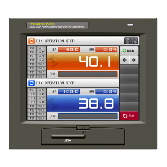
- Page 1 TEMP2020 - SERIES TEMP2720 TEMP2520 TEMP2320 OPERATION MANUAL Programmable Controller...
-
Page 2: Table Of Contents
SAMWONTECH ※ This manual applies to TEMP2320, TEMP2520 and TEMP2720. ※ The model stated the manual content is TEMP2520. Contents Safety Precautions Handling overview Initial operation flow ………………………………………………………………………………·· Setting Buttons ························································································ Input Keypad ························································································ OPERATION setting MAIN MENU screen ………………………………………………………………………………··... - Page 3 SAMWONTECH SCREEN DISPLAY setting Screen Display setting ……………………………………………………………………………· DI ERROR HISTORY ………………………………………………………………………………·· RESERVE OPERATION setting ……………………………………………………………………………· USER SCREEN setting USER SCREEN viewer ……………………………………………………………………………· Creating BMP File for USER SCREEN image ………………………………………………·· 10. Communication Errors massage ………………………………………………………………·· * Engineering Units 1st Edition of TEMP2020_Series IM : Dec. 15. 2008...
-
Page 4: Safety Precautions
(B) Read and understand this Operation Manual carefully before using the product. (C) This Operation Manual describes functions and features of the product in detail, and SAMWONTECH can not guarantee against over applications would suit a customer’s particular purpose which is not described in this manual. - Page 5 (A) SAMWONTECH does not guarantee or accept responsibility for this product other than the clauses stated in our warranty policy. (B) SAMWONTECH assumes no liability to any party for any loss or damage, direct or indirect, caused by the use or any unpredictable defect of the product.
-
Page 6: Handling Overview
SAMWONTECH 2 Handling overview ▶ This product is Programmable Controller configured with Interactive Touch Screen type, which is designed for user convenience. 2.1 Initial operation flow ▶ Supplying the power after completing installation correctly, loading screen will appear for loading time then Initial Logo screen will be displayed. -
Page 7: Setting Buttons
SAMWONTECH 2.2 Setting Buttons ▶ [Table2-1] describes Basic Setting Buttons. Table 2-1. Basic Set Button Button Type Description Touch “Set Parameter” part at FIX STOP/RUN Screen, and is used to set desired parameter. Touch “Pattern No” part at Program Stop Screen, and is used to set desired Pattern Number by user. -
Page 8: Input Keypad
SAMWONTECH 2.3 Input Keypad ▶ When you pressing the button, the following Input Keypad appears and the required data value can be set by using this Input Keypad. ▶ If the setting value is out of the available range, ‘LIMIT ERROR’ message will appear with a ‘BEEP’... - Page 9 SAMWONTECH ⑤ Input Key to set Aux. Output ☞ Refer to Aux. Output in [Control & Transmit Output] in [Installation Manual] for Aux. Output setup. ⑥ User tag Input key for CH1, CH2 ⑦ LIMIT ERROR message when out of available rage KEY LOCK Release ▶...
- Page 10 SAMWONTECH 2.3.2 Set Point input ▶ All Set Points can be set by using above mentioned numeric, alpha-numeric and Time Signal setting Keypad. ▶ Numeric Input Keypad will appear with pressing button to input Set Point. ▶ For the TIME SIGNAL setting Keypad, refer to [5.4 TIME SIGNAL].
-
Page 11: Operation Setting
SAMWONTECH 3. OPERATION setting 3.1 MAIN MENU screen ▶ MAIN MENU screen is organized into six sections. This MAIN MENU screen is the central gate way screen to move into Low parameter section ▶ Press the (MAIN) button to move to this MAIN MENU screen. -
Page 12: Fix Operation
SAMWONTECH 3.2 FIX Operation 3.2.1 FIX STOP screen ▶ Under setting ‘FIX’ operation for ‘OPERATION MODE’ on [4. FUNCTION & FIX OPERATION setting], when you press [OPER. SCREEN] button on the MAIN MENU screen, this FIX STOP screen will appear. - Page 13 SAMWONTECH ▶ CH1. CH2 SET VALUE input method is as follows. ▶ Input Key is displayed when touch “SET POINT” in the screen to enter set value. [Figure 3-4] CH1, CH2 Set Value Input Screen Table 3-1. FIX STOP Screen Parameter...
- Page 14 SAMWONTECH 3.2.2 The 1 FIX RUN screen ▶ This screen displays Process Value, Set Point, Control Output and Lamp Operation Status. ▶ Set Point Input Key is displayed during operation when touch “SP” part. ▶ Able to select Asynch/Synch Operation at [4. F UNCTION & FIX OPERATION].
- Page 15 SAMWONTECH ⑤ Displays CH2 Set Point.. ⑥ Red status lamp in CH2 indicates “ON”, and dark gray for “OFF” status. ☞ Status Lamp can be set at [SYSTEM INITIAL SET Screen] in [Installation Manual]. ☞ Up to 20 Status lamp per channel can be set at [SYSTEM INITIAL SET Screen], and only 16 status lamps are displayed at [The 1 FIX RUN screen].
- Page 16 SAMWONTECH 3.2.3 The 2 FIX RUN screen ▶ This screen displays Process Value, Set Point, Control Output and Lamp Operation Status. ▶ Set Point Input Key is displayed during operation when touch “SP” part. ▶ Pressing the STOP/RUN button during Synch Operation will move to CH1, CH2 STOP/RUN operation.
- Page 17 SAMWONTECH 3.2.4 The 3 FIX RUN screen ▶ Following screen explains for CH1, and it is same for CH2. ▶ Left side of screen indicates Process Value, Set Point, Control Output Value. ▶ ( ) Check Box set whether to display Data on the Screen.
- Page 18 SAMWONTECH 3.2.5 FIX OPERATION STOP Screen ▶ Fix Operation stops running with following “TIME OPERATION END” message when the time set for CH1 and CH 2 at [4. FUNCTION & FIX OPERATION]. ☞ “TIME SET RUN” can be set same for CH1, CH2, but its running start time may be different because they operate individually.
-
Page 19: Program Operation
SAMWONTECH 3.3 PROGRAM Operation 3.3.1 PROGRAM STOP screen ▶ Under setting ‘PROG’ operation at CH1, CH2 ‘OPERATION MODE’ on [4. FUNCTION & FIX OPERATION setting], when you press [OPER. SCREEN] section on the MAIN MENU screen, this PROGRAM STOP screen will appear. - Page 20 SAMWONTECH ▶ Following is the method to input CH1. CH2 pattern number. ▶ Input Key is displayed when touching “PATTERN NUMBER FOR OPER” area for pattern number input. [Figure 3-14] CH1, CH2 Pattern Number Input Screen Table 3-2. PROGRAM STOP Screen Parameter...
- Page 21 SAMWONTECH 3.3.2 The 1 PROGRAM RUN screen ▶ Displays Process Value, Set Point, Control Output and Lamp Operation Status. ▶ It is unable to set Pattern Number during operation. ▶ Able to set Asynch/Synch Operation at [4. FUNCTION & FIX OPERATION].
- Page 22 SAMWONTECH ⑥ Red status lamp in CH2 indicates “ON”, and dark gray for “OFF” status. ☞ Status Lamp can be set at [SYSTEM INITIAL SET Screen] in [Installation Manual]. ☞ Up to 20 Status lamp per channel can be set at [SYSTEM INITIAL SET Screen], and only 16 status lamps are displayed at [The 1 PROGRAM RUN Screen].
- Page 23 SAMWONTECH 3.3.3 The 2 PROGRAM RUN screen ▶ Displays Process Value, Set Point, Control Output and Lamp Operation Status. ▶ CH1, CH2 STOP/RUN when pressing STOP/RUN button during Sync Operation ① ⑤ ② ⑥ ③ ⑦ ④ ⑧ [Figure. 3-17] The 2 PROGRAM RUN Screen (CH1) ⑨...
- Page 24 SAMWONTECH ☞ [SEG TIME: 000H00M00S/000H00M00S] Former time indicates Segment progress time, and latter indicates Set Time in [5.1 PROGRAM PATTERN SET]. ⑧ Display program run progress time. ⑨ Moves to CH1 or CH2 screen. ⑩ Executes or releases Auto Tuning with current set value.
- Page 25 SAMWONTECH 3.3.5 PROGRAM operation STOP Screen ▶ Once the operation has completed normally as all setting on processed pattern, PROGRAM operation will stop and ‘PATTERM OPERATION END’ message appears show as [Figure 3-20, Figure 3-21]. ▶ However, this message will not appear if the operation is stopped by force pressing ‘STOP’ button.
-
Page 26: Fix And Program Operation
SAMWONTECH 3.4 FIX and PROGRAM Operation 3.4.1 FIX AND PROGRAM STOP screen ▶ CH1, CH2 operation type can be selected as “FIX” and “PATTERN” each at [4. FUNCTION & FIX OPERATION]. ▶ [Figure 3-22] is “Asynch” selected screen at [4. FUNCTION & FIX OPERATION]. - Page 27 SAMWONTECH ▶ “Set Point”, “Pattern No.” input method for CH1 FIX OPERATION, CH2 PROGRAM OPERATION is as follows. ▶ Input key is displayed when touching “Set Point” area in the screen for CH1 set point input. ▶ Input key is displayed when touching “Pattern No” area in the screen for CH2 pattern no. input.
- Page 28 SAMWONTECH ▶ “Set Point”, “Pattern No.” input method for CH1 PROGRAM OPERATION, CH2 FIX OPERATION is as follows. ▶ Input key is displayed when touching “Pattern No” area in the screen for CH1 pattern no. input. ▶ Input key is displayed when touching “Set Point” area in the screen for CH2 set point input.
- Page 29 SAMWONTECH 3.4.2 The 1 FIX AND PROGRAM RUN screen ▶ Displays Process Value, set point, control output value and lamp operation status. ▶ Able to set each Channel operation type at [4. FUNCTION & FIX OPERATION]. ▶ Able to set Asynch/Synch Operation at [4. FUNCTION & FIX OPERATION].
-
Page 30: Auto Tuning Screen
SAMWONTECH 3.5 AUTO TUNING Screen ▶ Auto Tuning type has two types of Seg PID type and Zone PID type. ▶ Hold and Step key can not be used during Auto Tuning at Program Run. 3.5.1 Auto Tuning (Seg) ▶ Seg PID type auto tunes based on current set point, and the tuning value is stored to “PID No” which is set by Auto Tuning Parameter. - Page 31 SAMWONTECH ▶ FIX and PROGRAM: AUTO TUNING(SEG) ☞ INRH, INRL : Indicates input sensor range. ☞ Threshold 1 ~4: Indicates threshold value of PID No. ☞ Auto Tuning : Indicates PID No selected for Auto Tuning. ☞ Auto Tuning Set Point: Indicates currently running Set Point.
- Page 32 SAMWONTECH 3.5.2 AUTO TUNING (ZONE) ▶ Tuning is performed with the center value as target of PID group threshold value which is set at Auto Tuning Parameter, and the tuning value is stored to selected PID No. ▶ Current set point becomes Auto Tuning Set Point during Auto Tuning execution.
- Page 33 SAMWONTECH ▶ FIX and PROGRAM: AUTO TUNING (Zone) ☞ INRH, INRL : Indicates input sensor range. ☞ Threshold 1 ~4: Indicates threshold value of PID No. ☞ Auto Tuning : Indicates PID No selected for Auto Tuning. ☞ Auto Tuning Set Point: Indicates currently running Set Point.
- Page 34 SAMWONTECH ▶ Following is the Tuning Point Calculation method. ① Tuning Point : 1 ☞ Execute PID1 Segment Auto Tuning. Threshold 1 – INRL - PID1 Auto Tuning Set Point = INRL + ② Tuning Point : 2 ☞ Execute PID2 Segment Auto Tuning.
-
Page 35: Auto Tuning And Tuning Point
SAMWONTECH 3.6 AUTO TUNING and TUNING POINT ▶ Auto-Tuning is a strong function to establish optimal P.I.D value automatically by calculating the characteristics of the control system. ▶ While generating ON/OFF control output signal for 2.5 cycles, the controller measures the PV response of the control system with a limit cycle method and calculate the optimal P.I.D value with the oscillation... -
Page 36: Function & Fix Operation Setting
SAMWONTECH 4. FUNCTION & FIX OPEARTION setting ▶ Press [FUNCTION&FIX] button on MAIN MENU screen to enter into this function section. ▶ This screen is to set parameters concerned additional function for general operation and FIX operation. 4.1 Operation mode & Functions ▶... - Page 37 SAMWONTECH Table 4-1. PROGRAM STOP Screen Parameters Parameters Range Units Default Operation Type Pattern, Fix Pattern Return from Outage Stop, Cold, Hot Stop Fuzzy Feature Off, On CH1 SP Slope CH1.EUS(0.00 ~ 100.00%) / MIN CH1.EUS / MIN CH1.EUS(0.00%) /MIN CH2 SP Slope CH2.EUS(0.00 ~ 100.00%) / MIN...
-
Page 38: Fuzzy Function
SAMWONTECH 4.2 FUZZY function ▶ FUZZY function can effectively control the overshoot that may occur when intense fluctuating load or frequent Set Point changing. ▶ Before PV approaches to SP, automatically calculated SUPER SP can restrain overshoot. ▪ FUZZY ‘OFF’... -
Page 39: Sp Slope Function
SAMWONTECH 4.3 SP SLOPE function ▶ SP SLOPE function to make the Set Point ascend or descent gradually overtime. ▶ When changing the Target SP during FIX run operation, NSP (current SP) will be changed from current PV to Target SP gradually by assigned ramping rate. -
Page 40: Program Setting
SAMWONTECH 5. PROGRAM setting ▶ Press [PROGRAM SET] on MAIN MENU screen to enter into program setting section [Figure 5-1 PROGRAM SET screen]. ▶ This PROGRAM SET menu is composed with 6 groups concerned program operation setting. ① ③ ②... -
Page 41: Program Pattern Setting
SAMWONTECH 5.1 Program PATTERN setting ▶ This screen is to set programming segments of each pattern. ▶ Press [PATTERN SET] button on PROGRAM SET menu to enter into this screen. ▶ Following screen explains for CH1, and it operates same with CH2 screen. - Page 42 SAMWONTECH PROGRAM RUN START ▶ PROGRAM OPERARTION START is done according to the setting of STC (START CODE) setup. (1) Setting Point Preferred Program Operation (STC = SSP) ▶ When program operation starts, SP starts from SSP and operates until SP1 under 1SEG for set Time 1(TM1).
- Page 43 SAMWONTECH ④ When there is only rising section without maintaining section. Program Present Pointing Value Operation Start Operation Not started E(SSP) Segment ⑤ When maintaining section starts from Segment 1. Present Program Pointing Value Operation Start A(SSP) Segment (3) Time Preferred Program Operation (STC = T.PV) ▶...
- Page 44 SAMWONTECH ▶ This screen is to set Aux. Output. ▶ Select Aux. Output from [CONTROL & TRANSMISSION SET] in [Installation Manual]. ▶ It is displayed in red color at PATTERN SET screen, and can set Aux Output. ▶ Press the setup box, and Input Keypad will appear.
- Page 45 SAMWONTECH ▶ It displays the Start Code which is set to “SPV”. ▶ It displays the Start Code which is set to “SSP”. ▶ (Insert), (Delete) buttons are activated when button is activated. 1st Edition of TEMP2020_Series IM : Dec. 15. 2008...
- Page 46 SAMWONTECH ▶ Input key is displayed to set the setting value when pressing the Set Value button. ▶ Input key is displayed to set Segment Time when pressing the (Time). ▶ Input key is displayed to set Time Signal when pressing (Time Signal) button.
- Page 47 SAMWONTECH ▶ Input key is displayed to set when pressing (Time Signal) button, and (AUX) button appears when pressing the (TS) button at top right side to set Aux. Output. ▶ Input key is displayed to set Seg. Alarm when pressing the (Seg.
- Page 48 SAMWONTECH ▶ Press (Enter) button to complete time signal setting. ▶ Press (ESC) button to cancel input and disappear Input Keypad. ☞ Able to select and enter the required Time Signal group by pressing TS1 ~ TS8 button setting by [5.4 TIME SIGNAL SET].
-
Page 49: Repeat Operation
SAMWONTECH 5.2 REPEAT operation ▶ Press [REPEAT SET] button on PROGRAM SET menu screen to enter into this screen. ▶ This screen is to set repeat operation of entire current pattern and partial segment operation after complete of current operation. -
Page 50: Pattern File Edit
SAMWONTECH 5.3 Pattern FILE EDIT ▶ Press [FILE EDIT] button on PROGRAM SET menu screen to enter into this screen. ▶ This screen is to edit program by copy or delete pattern set on [5.1 Program PATTERN]. ▶ Currently processing pattern can not be deleted. - Page 51 SAMWONTECH ▶ ‘PARAMETER SETTING SET ERROR’ message will appear when editing with input error at original pattern number. [Figure 5-5] FILE EDIT screen - Error Table 5-3. FILE EDIT setting Parameters Parameter Range Units Default CH #n PATTERN NUMBER 1~40...
-
Page 52: Time Signal
SAMWONTECH 5.4 TIME SIGNAL ▶ Press [TIME SIGNAL] button on PROTRAM SET menu screen to enter into this screen. ▶ This screen is to establish each 20 types of TIME SIGNAL setting. Refer to the [5.4.3 Description of TIME SIGNAL operation]. - Page 53 SAMWONTECH [Figure 5-8] TIME SIGNAL SET screen – TS12 to TS17 ① ② [Figure 5-9] TIME SIGNAL SET screen – TS18 to TS20 ① DEALY TIME is to set the start time of TIME SIGNAL activating ‘ON’ at segment. TS event output will become ‘ON’...
- Page 54 SAMWONTECH 5.4.3 Description of TIME SIGNAL operation Setting TIME SIGNAL Operation OPER.TIME 1. DELAY TIME = 000.00.00 TIME SIGNAL 2 N SEG TIME≥ SEGMENT (N-1) SEG TIME N SEG TIME (N+1) SEG TIME DELAY TIME +OPER.TIME OPER.TIME DELAY TIME 2. DELAY TIME ≠...
-
Page 55: Wait Function
SAMWONTECH 5.5 WAIT function ▶ Press [WAIT SET] button on PROTRAM SET menu screen to enter into this screen. ▶ This screen is to set WAIT Function parameter. ▶ WAIT Function established on this screen can be applied to program segment setting on [5.1 Program PATTERN]. - Page 56 SAMWONTECH ▶ The interaction between WAIT Operation and WAIT TIME is shown as below. ① Release WAIT Operation within WAIT TIME Wait Time Set Point Wait Zone Wait Zone Release WAIT Operation WAIT Operation Step to the next Segment (Actual Delay Time)
-
Page 57: Pattern Name Input
SAMWONTECH 5.6 PATTERN NAME input ▶ Press [PATTERN NAME] button on PROTRAM SET menu screen to enter into this screen. ▶ This screen is to input the experiment name of each pattern. ▶ Refer to [Figure 3-11 The 1 PROGRAM RUN Screen]. -
Page 58: Graph & Rec. Setting
SAMWONTECH 6. GRAPH & REC. setting 6.1 PATTERN GRAPH VIEW ▶ This screen displays Operation Pattern and Progressing Time in Graph on Program Operation. ▶ Following screen explains for CH1, and it operates same with CH2 screen. ▶ Selecting [Graph & Store] at the top left of [Figure 3-1 Main Menu] will move the screen to [Figure 6-1 Graph &... - Page 59 SAMWONTECH ④ Button to move to the next / previous screen. ⑤ Move to CH1 or CH2 screen. ⑥ Button to move to the next / previous paragraph by time interval. ▶ This is the PATTERN GRAPH VIEW screen when displaying process time of current pattern operation.
- Page 60 SAMWONTECH ▶ Input Keypad for pattern number to display by trend graph. [Figure 6-4] Pattern Number Input Screen Table 6-1. PATTERN GRAPH VIEW setting Parameters Parameter Range Units Default CH #n PATTERN NUMBER 1 ~ 40 30 Min, 1 Hour, 3 Hour, 6 Hour, VIEW TIME 30 Min.
-
Page 61: Trend Graph View & Data Processing
SAMWONTECH 6.2 TREND GRAPH view & DATA processing ▶ This screen is to open specific recorded trend data file at the [3.3.4 The 3 PROGRAM RUN screen] or [3.2.4 The 3 FIX RUN screen] and show that trend data by graph. - Page 62 SAMWONTECH ▶ [Figure 6-7 Trend Graph screen – PV FILE list] shows how to open the trend data file in internal memory stored at [3.3.4 The 3 PROGRAM RUN screen] or [3.2.4 The 3 FIX RUN screen]. ▶ Refer to [3.3.4 The 3 PROGRAM RUN screen] or [3.2.4 The 3...
-
Page 63: Recording Trend Graph On Internal Memory
SAMWONTECH 6.3 Recording TREND GRAPH on internal Memory ▶ This screen is to establish parameters for recording data on [3.3.4 The 3 PROGRAM RUN screen] or [3.2.4 The 3 FIX RUN screen]. ① ② ③ [Figure 6-8] Trend Graph setting screen ①... -
Page 64: Data Transmission With Sd Memory Card
SAMWONTECH 6.4 Data Transmission with SD memory card ▶ This screen is to set the parameters concern data logging and up / download with SD memory card. ☞ This screen will be hidden without SD card option. ① ② ③... -
Page 65: Screen Display Setting
SAMWONTECH 7 SCREEN DISPLAY setting 7.1 Screen Display settings ▶ Press the DISPLAY SET on MAIN MENU screen to enter this display setting section. ▶ This screen is to set parameters concerned screen display such as character font, LED brightness, Buzzer and Backlight off time. - Page 66 SAMWONTECH ▶ Screen to set Tag Name for CH1, CH2. [Figure 7-2] USER TAG NAME SET Screen Table 7-1. DISPLAY setting Parameters Parameter Range Units Default PV PONT SELECT HEAD, NORM, ART HEAD BACKLIGHT SAVING 0 ~ 99 MIN LED BRIGHTNESS...
-
Page 67: Di Error History
SAMWONTECH 7.2 DI ERROR HISTORY ▶ This screen shows the history of date and time on DI ERROR occur. ▶ Max. recent 30 DI ERROR history recording displayed. ☞ If more than 30 errors, recent 30 data will be displayed. - Page 68 SAMWONTECH ▶ [Figure 7-4] and [Figure 7-5] are screens when occurring DI ERROR. ▶ DISPLAY METHOD for DI ERROR occur between TEXT and PICTURE can be set on [11. DI CONFIG] of the [Instruction Manual]. ▶ The (EXIT) button is used to return to the Operation screen.
-
Page 69: Reserve Operation Setting
SAMWONTECH 8 RESERVE OPERATION setting ▶ Press [RESERVE SET] on MAIN MENU screen to enter into this time setting section. ▶ This screen is to adjust the current time and set the time for RESERVE Operation. ▶ Following screen explains for CH1, and it operates same with CH2 screen ③... - Page 70 SAMWONTECH [Figure 8-3] PROG Operation screen on RESERVE (Synch) Table 8-1. RESERVE OPERATION setting Parameters Parameter Range Units Default Year 2000~2099 Month 1~12 Date 1~31 CURRENT TIME AM/PM AM, PM Hour 1~12 Minute 0~59 Year 2000~2099 2009 Month 1~12 Date...
-
Page 71: User Screen Setting
SAMWONTECH 9 User Screen setting 9.1 USER SCREEN viewer ▶ 16 individual images can be used as USER SCREEN. ▶ USER SCREEN viewer will be activated by no key input for established [START TIME] on [12. PICTURES VIEW setting] of [Installation Manual], and USER SCREEN images will display with rotating by [INTERVAL TIME], when using that function with more than one picture. -
Page 72: Creating Bmp File For User Screen Image
- When saving your image in [Photoshop] save as BMP. ☞ Name the folder inside the SD CARD as BMP. ※ More information on making a BMP file can be downloaded of SAMWONTECH's website. 1st Edition of TEMP2020_Series IM : Dec. 15. 2008... -
Page 73: Communication Errors Massage
SAMWONTECH 10 COMMUNICATION ERROR message ▶ ‘CONTROL PART WAS DISCONNECTED!’ message will appear on Operation screen shown as [Figure 10-1 Communication Error with CONTROL UNIT] when communication error between the CONTROL UNIT and the DISPLAY PANEL occurs. ▶ ‘I/O BOARD WAS DISCONNECTED!’ message will appear on Operation screen shown as [Figure 10-2 Communication Error with I/O BOARD] when communication error between the I/O BOARD and the DISPLAY PANEL occurs. -
Page 74: Engineering Units
SAMWONTECH (ENGINEERING UNITS) EU and EUS are used for the scaling of the parameters of the controller. – EU, EUS ▶ If the sensor type or minimum/maximum input range (INRH, INRL) is adjusted, the EU(), EUS() parameters also change proportionally (minimum and maximum input ranges are reset). - Page 75 Gyeonggi-do, Korea 420-773 TEL : +82-32-326-9120 FAX : +82-32-326-9119 Website : http://www.samwontech.com e-mail : webmater@samwontech.com The contents of this document are subject to change without prior notice. Printed in Korea : 2008(A) All Rights Reserved. Copyright ⓒ 2008 SAMWONTECH CO.,LTD.
Need help?
Do you have a question about the TEMP2020 series and is the answer not in the manual?
Questions and answers