
Related Manuals for Samwontech NOVA541


Summary of Contents for Samwontech NOVA541
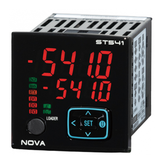
- Page 1 Digital Controller ST541 User’s Manual SAMWONTECH CO., Ltd.
- Page 2 NOVA541 Limitations in use This product was designed and manufactured for general industrial equipments. Special cares on safety is required in the case of using in following equipments. Users should take precautionary measures on Fail Safe design, periodical checkup, safety of the whole system.
- Page 3 (1) This manual should be passed on the end user and kept at a suitable place for easy review. (2) Before using the product, the operator should read this book carefully and understand the operation procedure. (3) This manual describes the functions of the product in detail. Samwontech does not - 2 -...
- Page 4 (1) Samwontech co., Ltd does not make any warranties regarding the product except Warranty conditions which mentioned in this manual. (2) Samwontech assumes no liability to any party for any loss or damage, direct or indirect, caused by the use or any unpredictable defect of the product.
- Page 5 (2) The fixing cost will be charged for defective product after warranty period. This charge will be the actual cost of the fixing estimated by Samwontech. (3) It will be charged even if within warranty period for following cases.
-
Page 6: Precautions On Environment And Installations
NOVA541 Precautions on Environment and Installations Environmental Precautions (1) Be sure to power on and operate the controller after installation on a panel to prevent electric shock. (2) Do not install the controller at following places or environment ■ Anybody may touch the terminal inadvertently ■... - Page 7 NOVA541 (5) Turn off the main power of the control unit before wiring to prevent electric shock. (6) The power rating of the controller is 10 VA max. at 100∼240VAC, 50/60Hz. Be sure to use suitable power source to prevent overheating or electric shock.
-
Page 8: Engineering Units - Eu, Eus
NOVA541 Engineering Units – EU, EUS ▶ EU and EUS are used for the scaling of the parameters of the controller. ☞ EU( ) : The Range of the Instrument, Engineering Unit ☞ EUS( ) : The Range of the span of the Instrument, Engineering Unit... -
Page 9: Alpha-Numeric Displays Of The Product
NOVA541 Alpha-numeric Displays of the product Numbers in 7-Segment LED Display Half - Half 1 Half -1 Alphabets in 7-Segment LED Display A, a B, b C, c D, d E, e F, f G, g H, h I, i... -
Page 10: Table Of Contents
NOVA541 CONTENTS Important Safety Guide Precautions on Environment and Installations Engineering Units – EU, EUS Alpha-numeric Displays of the product PAGE 1. Introduction 1-1 Product outline 1-2 KEY Operaion 1-2-1 Part names and functions 1-2-2 KEY Operation 1-2-3 Front panel and LEDs... - Page 11 NOVA541 3-3 Mounting procedure 3-4 Disassembly of TERMINAL CASE ASSY and wiring 4. Functions 4-1 Sensor input (G.IN) 4-1-1 Input Type 4-1-2 Temperature unit 4-1-3 Input range 4-1-4 Decimal point 4-1-5 PV display range 4-1-6 Input filter 4-1-7 Display filter...
- Page 12 NOVA541 4-3-10 PASSWORD 4-3-11 ON/OFF Mode 4-3-12 Initialization of the controller 4-4 Communication (G.COM) 4-4-1 Protocol selection 4-4-2 Baud rate 4-4-3 Parity 4-4-4 Stop Bit 4-4-5 Data Length 4-4-6 Communication Address 4-4-7 Response Time 4-4-8 Remote Bias at Synchronized RUN 4-5 Auto Tuning (G.AT)
- Page 13 NOVA541 4-8-7 Derivation time 4-8-8 Manual set value of Integration time 4-8-9 Proportional band (cooling control) 4-8-10 Integration time (cooling control) 4-8-11 Derivation time (cooling control) 4-8-12 DEAD BAND 4-8-13 PID Zone setting 4-8-14 PID DEAD BAND 4-8-15 Deviation value used in deviation PID 4-9 Inner Signal Group (G.IS)
- Page 14 NOVA541 5-5-1-1 Function code-03 5-5-1-2 Function code-06 5-5-1-3 Function code-08 5-5-1-4 Function code-16 5-5-2 Error Code 5-6 SYNC Communication 5-6-1 SYNC-Master 5-6-2 SYNC-Slave 5-7 D-Register Map 5-7-1 Process 5-7-2 Function 5-7-3 Set Point 5-7-4 Signal 5-7-5 Alarm 5-7-6 PID 5-7-7 IN/OUT * D-Register 0000∼0499...
-
Page 15: Introduction
NOVA541 1. INTRODUCTION 1-1. Product Outline ST541 is a digital controller with advanced design and functions. Short body (78 mm) is convenient to install at a small space. More informative displays such as 5-digit PV display, 8 status lamps, and comprehensive display menus are equipped. - Page 16 NOVA541 - Thermocouple (T/C ): K, J, E, T, R, B, S, L, N, U, W, PLA II, C - RTD : PtA, PtB, PtC, PtD, JPtA, JPtB - DC Volt : 0.4 ~ 2V DC, 1 ~ 5V DC, 0 ~ 10V DC, -10 ~ 20mV DC, 0 ~ 100mV DC (4 ~ 20mA DC: 250Ω;0.1% shunting to 1~5V)
- Page 17 NOVA541 ▣ Model and Suffix Code Type Suffix Code Function S*541 - T : Digital Controller Control Normal Control Method Heat/Cool Control Power 100~240V AC(50/60Hz) Supply 24V AC(50/60Hz) / 24V DC RS485/232 /SUB Dependent 3 Relay Option1 DI 2 Points...
-
Page 18: Key Operaion
NOVA541 1-2. KEY operation 1-2-1 Parts names and functions Name Function ▪ To select a parameter or enter the setting value "SET" ▪ To change the display screen in RUN screen (SET) ▪ "SET" KEY press 3 sec at Run screen → MENU screen ▪... -
Page 19: Key Operation
NOVA541 1-2-2 KEY operation a) "∧", "∨" KEY : digit display limit b) DIGIT carry operation when increasing or decreasing ▪ increasing Pressing "∧" KEY at digit "9" (except 5D,4D position), carry digit is added to upper next digit. ▪ decreasing ①... - Page 20 NOVA541 - When the value reaches upper or lower limit, MAX or MIN value will be displayed.. ex) S-TM = OFF, 0.01 ~ 99.59 일 경우 If a user set a value higher than 99.60, the maximum value of S.TM, 99.59 will be set and displayed.
-
Page 21: Front Panel And Leds
NOVA541 G.RET SET KEY ○ ○ KEY 3초 RET.H RET.L SET KEY g) "- (MINUS)" position In case MSD (the most significant digit) is in 1D, the position of (-) is 2D 2D, the position of (-) is 3D 3D, the position of (-) is 4D... -
Page 22: Terminal Layout And Connection Diagram
NOVA541 1-3. Terminal layout and diagram 1-3-1 Terminal Layout Description Standard Option Standard Option OUT1+(SSR/SCR) OUT1+(DCV) POWER N OUT1,2-(SSR/SCR) OUT1-(DCV) POWER L OUT2+(SSR/SCR) INPUT A INPUT B+ INPUT B- RTX+ EVENT1(RELAY) EVENT1(RELAY) RTX- EVENT1_COM1 EVENT2(RELAY) EVENT2(RELAY) EVENT3(RELAY) EVENT2_COM2 EVENT_COM 1-3-2 단자도... -
Page 23: Parameter Map (Deployment Diagram)
NOVA541 1-4. Parameter Map 1-4-1 Parameter Flow Power ON RUN screen STOP H.MV SET key 3 s Heating MV RUN status is the 1 MV display (H/C Type) ‘STOP’ screen screen SET key 3s or No Key 5 min. MENU screen ▼/▲... - Page 24 NOVA541 RUN screen HBCD C.MV Cooling MV Heater Break User Screen2 User Screen1 Option (H/C Type) If it is set If it is set MENU screen ▼ ▲▼ ▼/▲ ▼/▲ ▼/▲ ▼/▲ ▼/▲ G.RET G.COM G.OUT G.ALM G.IS G.HBA ALT1 1.IST...
-
Page 25: Initial Parameter Setting Sequence
NOVA541 1-5. Initial parameter setting sequence 1. Wiring and Power ON After wiring according to installation manual, power ON Set the sensor kind first of all and most 2. Sensor type (IN-T) set parameters will be reset at this time accordingly. -
Page 26: Electrical Wiring
NOVA541 2. Electrical Wiring Precaution ▪ Switch off the main power supply and make sure that no current flows in all the circuits before the wiring work. ▪ Do not touch the real terminal part while the power is on. -
Page 27: Wiring
NOVA541 ■ Countermeasures against noise Notice following guide while wiring work. (1) The wires of input signal should be apart from power line and grounding line. (2) Use a shielded wire to guard against a noise from electrostatic induction. Multi-point grounding should be avoided and connect the shield wire to ground terminal if necessary. -
Page 28: Control Out
NOVA541 (가) 측온저항체 입력(RTD INPUT) (나) 직류전압 입력(DC VOLTAGE INPUT) SHIELD SHIELD Ground (3) DC CURRENT INPUT SHIELD DCmA Ground 2-4-3 Control out ▶ Be careful of the polarity. The wrong wiring may cause a trouble in the product. ▶ Use a shielded wire for analog input and the shield should be 1-point grounded. -
Page 29: Digital Output And Input
NOVA541 (2) Retransmission (RET) Receiver SHIELD (recorder) 4~20mA DC, 500Ω max Ground 2-4-4 Digital output and input ▶ RELAY : Normal Open 30VDC 1A max, 250VAC 1A max. RLY_NO RLY_NO RLY_COM RLY_NO RLY_NO RLY_NO RLY_COM RLY_COM ▶ Use a mechanical contactor (non-voltage type) as relay for the digital input (DI). -
Page 30: 2-4- Auxiliary Relay
NOVA541 2-4-5 Auxiliary Relay Precaution ▪ If the wattage of the load is greater than the rating of output relay, an auxiliary relay should be used to on/off power on the load. ▶ When an inductive switch as a relay and a solenoid valve is used, it may be a noise source. A protective circuit should be installed to suppress a surge. -
Page 31: Ct Sensor For Detecting Heater Break
NOVA541 2-4-6 CT sensor for detecting Heater Break ▪ This function is available only when OUT type is SSR or RELAY. ▪ The winding ratio of CT Sensor should be 800:1. ▪ To detect the heater current, the output pulse width should be longer than 200 ms. -
Page 32: Mounting Of The Product
NOVA541 3. Mounting Precautions ▪ To prevent an accident or trouble, the environmental operation conditions should be observed the specifications specified in the manual (temperature, humidity, voltage, vibration, shock, mounting, atmosphere) ▪ Do not block any vent hole on the controller to prevent a fire or a failure. -
Page 33: Mounting Procedure
NOVA541 ▶ When close mounting more than 3 ea., the ambient temperature should be kept below 40℃. ▶ The gap in vertical direction should be greater than 50mm. 3-3. Mounting procedure ▶ Mounting slope angle is allowed within 10 degree from horizontal position in both up and down directions. -
Page 34: Disassembly Of Terminal Case Assy And Wiring
NOVA541 3-4. Disassembly of TERMINAL CASE ASSY TERMINAL CASE ASSY HOOK Terminal case (-) screw driver ▶ Wedge off the two hooks with a (-) screw driver and open up the terminal case assay. ▶ The wiring work can be done with TERMINAL CASE ASSY separated. -
Page 35: Functions
NOVA541 4. Functions 4-1. Sensor input (G.IN) Input Type (IN-T) : Thermocouple (TC), Resistive thermal detector (RTD), DC volt (DCV) In case of TC or RTD, the sensor type and temperature range should be selected. In case of DCV, the input types are classified with the range of input voltage. -
Page 36: Input Type
NOVA541 4-1-1 Input type ▪ Select the input type to use, considering sensor type and input range. ▪ Refer to Table 1 as a guide of sensor type and input range. Symbol Parameter Setting range Display Unit Default IN-T Input Sensor Type... -
Page 37: Decimal Point
NOVA541 4-1-4 Decimal point ▪ Determine decimal point place. ▪ When IN-T is one of TC, RTD group, IN.DP will skip. ▪ Decimal point place can be adjusted with IN.DP parameter when IN-T is one of DCV, mV. Symbol Parameter... -
Page 38: Display Filter
NOVA541 PV = Sensor Input × ( 1/1 + IN.FL ) IN.FL : OFF, 1∼120 sec Symbol Parameter Setting Range Display Unit Default IN.FL Input Sensor Filter OFF, 1 ∼ 120 Always 4-1-7 Display filter (D.FL) ▪ Reduce the fluctuation of PV display in FND. -
Page 39: Entire-Range Correction
NOVA541 (Refer to page77, “Error display and correction”) Symbol Parameter Setting range Display Unit Default R.SL RJC Select OFF, ON IN-T = TC 4-1-10 Entire-range correction (AL.BS) ▪ Adjust offset of PV display in entire range. PV = Input + Bias in the whole range(AL.BS) -
Page 40: Pv Limiter
NOVA541 (BS3 ~ BS2) ▪ BS.P2 ~ BS.P3 : B.PV = R.PV + ( R.PV – BS.P2 ) X ━━━━━━━━━━ + BS2 (BS.P3 ~ BS.P2) (BS4 - BS3) ▪ BS.P3 ~ IN.RH : B.PV = R.PV + ( R.PV – BS.P3 ) X ━━━━━━━━━━ + BS3 (IN.RH - BS.P3) - Page 41 NOVA541 Precaution ▪ If IN-T is changed, The parameters such as RH, RL, SH, SL will be initialized. ▪ The parameters of EU and EUS unit will be scaled with the sensor input range, therefore The parameters in G.IN should be set above all.
-
Page 42: Control Output (G.out)
NOVA541 4-2. Control Output (G.OUT) ▪ The kinds of output is determined by the parameters in G.OUT, OUT1, OUT2, EV1, EV2, EV3. ▪ As the type of output, SSR and SCR are available for OUT1, OUT2 and RELAY for EV1, EV2, EV3. -
Page 43: Output Control Direction
NOVA541 Forward and Reverse Control Action Control Out (MV) 100% Forward action Reverse action MV increases when PV is MV increases when PV higher than SP. is lower than SP 제어출력이 증가합니다. Deviation (PV-SP) 4-2-2 Output control direction (O.ACT) ▪ The direction of the control action : Reverse action (REV), Forward action (FWD). -
Page 44: Output Limit
NOVA541 Cycle Time ▪ Cycle time is valid only when output type is SSR (Solid State Relay) or RELAY. ▪ Cycle time is 1 period of ON + OFF time. ▪ In case the cycle time is 10 sec. (CT = 10) -
Page 45: On/Off Mode
NOVA541 Symbol Parameter Setting range Display Unit Default ON/OFF Hysteresis 0.0 ~ 10.0% H/C Type 0.5% HYS.H ON/OFF High Hysteresis EUS(0.0 ~ 10.0%) ON.OF = ON시 EUS(0.5%) HYS.L ON/OFF Low Hysteresis 4-2-7 ON/OFF mode output ▪ ON/OFF mode is activated by setting ON.OF = ON in Control Group (G.CTL). - Page 46 NOVA541 ▪ When the controller is a H/C type, PO is for HEAT port, POC is for COOL port. ▪ In MAN MODE, the output value by key input will go out regardless of ERROR. Symbol Parameter Setting range Display...
-
Page 47: Out Led Display
NOVA541 4-2-9 OUT LED Display ▪ MV OUT LAMP display mode. SSR : On/Off of MV Out Lamp is synchronized with that of SSR or RELAY output. SCR : MV Lamp blinks regardless of CT as SCR mode Symbol Parameter... -
Page 48: Control Functions (G.ctl)
NOVA541 4-3. Control Functions (G.CTL) 4-3-1 Reservation RUN ▪ Set the standby time to RUN starting Symbol Parameter Setting range Display Unit Default S-TM Start Time OFF, 0.01 ~ 99.59 min Always TIME 4-3-2 Run time setting ▪ Set the process run time. -
Page 49: User Defined Key
NOVA541 4-3-5 User defined key ▪ Pressing ⓤ key for 3 seconds, the function selected in U.KEY will be executed as a user defined function. Symbol Parameter Setting range Display Unit Default U.KEY User Define Key OFF, AT, A/M, R/S... -
Page 50: Pv Display High, Low Limit
User Password 0 ~ 9999 Always Precaution ▪ Be sure not to forget the PASSWORD. ▪ When the PASSWORD is lost. In this case, request a service to Samwontech. 4-3-11 ON/OFF Mode ▪ Set ON/OFF Mode active or disabled Symbol Parameter... -
Page 51: Communication (G.com)
NOVA541 4-4. Communication (G.COM) 4-4-1 Protocol selection ▪ Select a Protocol to use. ▪ Select PCC0 for PC Link or select PCC1 for PC Link with sum check. Symbol Parameter Setting range Display Unit Default Communication PCC0, PCC1, MBS.A, COM.P... -
Page 52: Communication Address
NOVA541 4-4-6 Communication Address ▪ Set the communication address. Networking is available up to 31 ea max. Symbol Parameter Setting range Display Unit Default ADDR Address 1 ~ 99 /RS Option 4-4-7 Response Time ▪ Set the response time. Symbol... -
Page 53: Auto Tuning (G.at)
NOVA541 4-5. Auto Tuning (G.AT) Auto Tuning ▪ Auto tuning is a strong function that the controller tests the characteristics of the control system, and calculates the optimal values of PID parameters. ▪ During auto tuning the controller makes ON/OFF control output 2.5 cycles, measure the PV response of the control system with a limit cycle method and calculate the P, I, D value with the oscillation data. -
Page 54: Auto Tuning
NOVA541 4-5-1 Auto tuning ▪ Make auto tuning start by setting AT = ON. ▪ This parameter is skipped when ON.OF = ON in G.CTL, ON/OFF mode. Symbol Parameter Setting range Display Unit Default Auto Tuning OFF, ON AUTO mode 4-5-2 GAIN setting ▪... - Page 55 NOVA541 Starting Auto tuning and stopping it ■ Starting ① Check the control system, PV input and heater power. ② Check if 「AT」lamp = OFF, in RUN mode not in READY mode. ③ Check if 「MAN」lamp = OFF, in Auto mode.
-
Page 56: Alarm (G.alm)
NOVA541 4-6. Alarm (G.ALM) Table 4. Types of Alarm Direction Standby NO Display Type ON Condition OFF Condition Fwd. Rev. No Yes AH.F ▣ ▣ Upper-limit PV PV ≥ ALn PV < (ALn - An.DB) AL.F ▣ ▣ Lower-limit PV PV ≤... - Page 57 NOVA541 Alarm Operation ▪ PV Upper-limit Alarm operation (AH.F) ALn : Alarm Point An.DB : Dead Band Delay Time RELAY Out ▪ PV Lower-limit Alarm operation (AL.F) An.DB : Dead Band ALn : Alarm Point Delay Time RELAY Out ▪ Upper-limit Deviation Alarm operation (DH.F) ALn.H : Deviation upper-limit...
- Page 58 NOVA541 ▪ Lower-limit Deviation Alarm operation (DL.F) An.DB : Dead Band ALn.L : Deviation Lower-limit Delay Time RELAY Out ▪ In band Deviation limits Alarm operation (DI.F) An.DB ALn.H : Upper-limit Dev. ALn.L : Lower-limit Dev. An.DB Delay Time Delay Time...
-
Page 59: Alarm Types
NOVA541 ※ Output Direction mode Forward (FWD) : ON when alarm condition, OFF when alarm off Reverse (REV) : OFF when alarm condition, ON when alarm off ※ The condition of Standby Power On Changing of Alarm Kind Changing SP 4-6-1 Alarm Kinds ▪... -
Page 60: Dead Band
NOVA541 4-6-4 Dead Band ▪ Set the dead band of Alarm1,2,3. Symbol Parameter Setting range Display Unit Default A1.DB Dead Band Alarm 1 A2.DB Dead Band EUS(0.0 ~ 100.0%) Always EUS(0.5%) Alarm 2 A3.AB Dead Band Alarm 3 4-6-5 Delay Time ▪... - Page 61 NOVA541 (나) DOWN SLOPE(↘ : SP ramping down) SK.DV time Alarm ▲ ▲ ▲ ① ② ③ ① Check the alarm from the point [ TSP = NSP ]. ② [ NPV < TSP + SK.DV ] “ON”. ③ [ NPV > TSP + SK.DV ] if “ON” once, it goes “OFF” when changing SP.
-
Page 62: Sp Group (G.sp)
NOVA541 4-7. SP group (G.SP) 4-7-1 Run/Stop Selection ▪ Select Run/Stop operation. Symbol Parameter Setting range Display Unit Default RUN/STOP Operation RUN, STOP Always 4-7-2 SP Kind ▪ Select SP Kind. Symbol Parameter Setting range Display Unit Default SP.SL SP Select Always R.SP, SP1, SP2, SP3, SP4... -
Page 63: Slope Of Ramping Up/Down
NOVA541 4-7-6 Slope of ramping up/down ▪ Set the ramping rate (EUS/min). Symbol Parameter Setting range Display Unit Default U.SLP Up Slope OFF, EUS(0.0%+1digit ~ Always D.SLP Down Slope 100.0%)/min Operation of Slope ▪ When changing TSP, the ramping rate is given from NPV to TSP by gradually changing NSP. -
Page 64: Pid Group (G.pid)
NOVA541 4-8. PID Group (G.PID) ▪ When On/Off mode, it is skipped. ON.OF = ON in G.CTL. Anti reset wind-up (ARW) ▪ ARW is an effective function to minimize the influence of an external perturbation or disturbance. ▪ When I=0 in PID parameter, ARW will not work. -
Page 65: Arw (Anti Reset Wind-Up)
NOVA541 4-8-1 ARW (Anti Reset Wind-up) ▪ Set the deviation band to prevent over-integration. Symbol Parameter Setting range Display Unit Default Anti-Reset Wind-Up AUTO(0.0) ∼ 200.0% Always 100.0% 4-8-2 Control Mode ▪ Select a mode of PID control. D.DV : MV change rate is small. Overshoot is small but it takes a bit long time to reach a TSP. -
Page 66: Pid Number
NOVA541 Fuzzy Operation ▪ When the variation of load power is great, or SP is changed frequently, overshooting appears generally. The Fuzzy function is effective to suppress the overshooting. ▪ Internal working sequence of FUZZY function ① When PV approaches SP, The calculation of SUPER SP is carried out. -
Page 67: Integration Time
NOVA541 4-8-7 Derivation time ▪ Set the Derivation time of PID. Symbol Parameter Setting range Display Unit Default Heat Derivative Time OFF, 1 ∼ 6000 sec Always 30 sec 4-8-8 Manual set value of Integration time ▪ If the Integration time (I) is “OFF”, the setting value will be assigned to the I term in PID. -
Page 68: Pid Zone Setting
NOVA541 1.RP Reference Point 1 PID = 1 EU(33.3%) EU(0.0%) ≤ 1.RP ≤ 2.RP 2.RP Reference Point 2 PID = 2 EU(66.7%) 1.RP ≤ 2. RP ≤ EU(100.0%) 4-8-14 PID DEAD BAND ▪ When using Zone PID, set the hysteresis at the zone boundary. - Page 69 NOVA541 2.RP 1.RP PID3 PID1 PID2 ▪ Deviation PID (4.PID) may be used by setting RDV value. When |PV-SP| >RDV, 4.PID set is applied. PID4 ZONE PID - 68 -...
-
Page 70: Inner Signal Group (G.is)
NOVA541 4-9. Inner Signal Group (G.IS) 4-9-1 Type to be referenced (.IST) ▪ Set the reference parameter of Inner signal action. Symbol Parameter Setting range Display Unit Default 1.IST Inner Signal Type 1 NSP, NPV, TSP Always 2.IST Inner Signal Type 2 4-9-2 Out or In band (.ISB) - Page 71 NOVA541 SEG1 SEG2 SEG3 SEG4 SEG5 50.5 50.0 30.0 29.5 [Example 2] ▪ INPUT = 0.0 ~ 100.0 → EUS 0.5% = 0.5 TYPE RANGE LOW RANGE HIGH DIRECT DELAY TIME 30.0℃ 50.0℃ OUT BAND 00.00 SEG1 SEG2 SEG3 SEG4...
- Page 72 NOVA541 [Example 3] ▪ INPUT = 0.0 ~ 100.0 TYPE RANGE LOW RANGE HIGH DIRECT DELAY TIME 30.0℃ 50.0℃ IN BAND 00.10 SEG2 SEG4 SEG5 SEG1 SEG3 50.0 30.0 DELAY TIME DELAY TIME [Example 4] ▪ INPUT = 0.0 ~ 100.0 →...
-
Page 73: Retransmission Group (G.ret)
NOVA541 4-10. Retransmission Group (G.RET) 4-10-1 Type of retransmission (RET) ▪ Set the type of retransmission signal. Symbol Parameter Setting range Display Unit Default Retransmission Type LPS, PV, SP, MV Always Retransmission Output 1) PV : 3.2mA ~ 20.8mA 12.0mA 3.2mA... -
Page 74: High And Low Limits (Reth, Retl)
NOVA541 4-10-2 High and low limits (RETH, RETL) ▪ Set high and low limits of retransmission Symbol Parameter Setting range Display Unit Default IN.RH(TC,RTD) RET.H Retransmission High Limit TC, RTD : IN.RL ~ IN.RH IN.SH(DCV) RET.T = PV DCV : IN.SL ~ IN.SH or SP시... -
Page 75: Heater Break Alarm
NOVA541 4-11. Heater Break Alarm (HBA) 4-11-1 Heater Current Display ▪ Display the current of the heater. Symbol Parameter Setting range Display Unit Default Heater Break Current HB.CD Display only HBA option시 Display 4-11-2 Heater Current Alarm Point ▪ Set the alarm point of heater current. - Page 76 NOVA541 HBA(Heater Break Alarm) ▪ HBA can work only when control output type is “SSR(Solid State Relay)” or “RELAY”. ▪ CT sensor should have the turn ratio of 800:1. ▪ Detection condition : MV output pulse width should be greater than 200ms. If the cycle time is set to 2 sec, MV should be greater than 10 % (200 ms duty ON).
-
Page 77: Error Display And Correction
NOVA541 Error Display and Correction Time Display Cause of Error Correction Power ON E.SYS Incomplete inspection Ask for repairs. Abnormal temperature Check the ambient temperature and E.RJC of terminal make it suitable for operation condition. PV Blinking Incomplete inspection Ask for repairs. -
Page 78: Communication (G.com)
NOVA541 5. Communication 5-1. Outline of communication ▪ NOVA series adopt RS485 communication method, Half-Duplex, 2 wire communication. ▪ A host computer can communicate with the controllers (up to 31 ea) through RS485 multi-drop network and using a protocol provided. -
Page 79: Communication Parameters
NOVA541 ▪ RS232 : The wiring between the controller and a host device. Master Station Controller RxD+ TxD- SHIELD Ground 5-3. Communication parameters ▪ The parameters of communication setup. Display Parameter Set value Description Default Standard protocol Standard protocol + Check Sum MODBUS ASCII COM.P... -
Page 80: Standard Protocol
NOVA541 5-4. Standard Protocol ▪ The standard protocol of NOVA series is composed of ASCII string. A user can read or write the contents of D-Register. ▪ There are two kinds of protocols which can be selected by COM.P parameter. -
Page 81: General Command
NOVA541 ② Information Command Command Function Model, Version Information of the controller ③ Error Response ▪ When an Error occurs during communication, NOVA sends a frame as following. Bytes Frame Address Error Code ▪ SUM is used only when COM.P = “1”... - Page 82 NOVA541 ex) Reading PV(D0001), SP(D0002) D-Register - Sending Frame : [stx]01RSD,02,0001[cr][lf] - Sending Frame (Check Sum) : [stx]01RSD,02,0001C5[cr][lf] If PV, SP are 50.0, 30.0 respectively, - Receiving Frame : [stx]01RSD,OK,01F4,012C[cr][lf] - Receiving Frame(Check Sum ) : [stx]01RSD,OK,01F4,012C19[cr][lf] ※ Converting 4digit hexadecimal number to decimal number ①...
-
Page 83: Write Command
NOVA541 If D0001 = 50.0 and D0002 = 30.0 - Receiving Frame : [stx]01RRD,OK,01F4,012C[cr][lf] - Receiving Frame (Check Sum) : [stx]01RRD,OK,01F4,012C18[cr][lf] 5-4-2-2 Write Command ① WSD Command ▪ WSD Command is used to write data to successive D-Registers. It is necessary to set the number of register, starting address, and array of data. -
Page 84: Monitoring Command
NOVA541 ② WRD Command ▪ WRD Command is used to write data to D-Registers randomly. It is necessary to set the number of registers and the pairs of address and data. Frame Format Normal Response Format Bytes Frame Bytes Frame... - Page 85 NOVA541 the number of registers, and array of addresses. ▪ To read data of the registers set by STD command, CLD command is used. ※ The register list set by STD vanishes when the controller power is OFF. It is necessary to use STD command to use CLD command after power recovery.
-
Page 86: Information Command
NOVA541 Frame Format Normal Response Format Bytes Frame Bytes Frame Address Address Data – 1 … … Data – n 16bit Word (4 character) 5-4-3 Information Command ▪ Information Command is used to get the controller information. Frame Format Normal Response Format... -
Page 87: Error Code
NOVA541 ex) Getting the controller information, Model, size, version. - Sending Frame : [stx]01AMI[cr][lf] - Sending Frame (Check Sum) : [stx]01AMI38[cr][lf] - Receiving Frame : [stx]01AMI,OK,SP541:4848[sp]V00-R00[cr][lf] - Receiving Frame (Check Sum) : [stx]01AMI,OK,SP541:4848[sp]V00-R002E[cr][lf] 5-4-4 Error Code ▪ On Error while communicating, NOVA Series sends a frame as following. -
Page 88: Modbus Protocol
NOVA541 5-5. MODBUS Protocol ▪ NOVA의 MODBUS communication has two modes, ASCII(COM.P = '2') and RTU(COM.P = '3'). ① Factors of MODBUS Item ASCII Start of text : (colon) none End of text CR+LF None Data length 7-bit (fixed) 8-bit (fixed) -
Page 89: Function Code-03
NOVA541 Function code – 03 ‘03’ 2 characters 8-bit D-Register Hi 2 characters 8-bit D-Register Lo 2 characters 8-bit Number of reg. Hi 2 characters 8-bit Number of reg. Lo 2 characters 8-bit Error detection 2 characters 16-bit End character... - Page 90 NOVA541 ▪ Response Format Factor ASCII Start character : (colon) none Communication address 2 characters 8-bit Function code – 06 ‘06’ 2 characters 8-bit D-Register Hi 2 characters 8-bit D-Register Lo 2 characters 8-bit Write Data Hi 2 characters 8-bit...
- Page 91 NOVA541 Data Lo 2 characters 8-bit Error Detection 2 characters 16-bit End character 2 characters (CR+LF) None ※ 진단코드와 내용 Code Description Loop-Back Test : Received Frame Return 5-5-1-4 Function code – 16 ▪ To write data to successive D-Register block up to 16 registers ▪...
-
Page 92: Function Code-08
NOVA541 Number of data Hi 2 characters 8-bit Number of data Lo 2 characters 8-bit Error Detection 2 characters 16-bit End character 2 characters (CR+LF) None 5-5-2 Error Code ▪ Error code is returned when an error is in the Frame. -
Page 93: Sync Communication
NOVA541 5-6. SYNC communication ▪ A master controller (COM.P='4') sends its operation parameters (Run/Stop, SP) to slave controllers (COM.P='5') periodically and the operation of slaves are synchronized with that of the master controller. Maximum 31 controllers can be networked. 5-6-1 SYNC-Master ①... -
Page 94: D-Register Map
NOVA541 5-7. D-Register Map ▪ D-Registers are provided for checking status of the controller. Basically, they are grouped by 100 addresses. D-Register Group name Description Read Write D0000~D0099 PROCESS Basic parameters ○ ○ D0100~D0199 FUNCTION Operation and functions ○ ○... -
Page 95: Function
NOVA541 D0017 SIGNAL.STS Current signal status D0019 ERROR Current error status D0020 PROC_TIME Time to run D0030 HB.CD Heater current 5-7-2 Function ▪ Function Group is related with operation and settings. D-Register Symbol Description D0101 R-S, RUN/STOP Operation state = ‘RUN’ or ‘STOP’... -
Page 96: Signal
NOVA541 D0214 TM.U Time unit D0216 U.SLP Ramping up slope D0217 D.SLP Ramping down slope 5-7-4 Signal ▪ Signal Group is related with Inner Signal. D-Register Symbol Description D0301 1.IST Type of Inner Signal1 D0302 1.ISB Inner Signal1 direction (in-band, out-of-band) D0303 1.ISH... -
Page 97: Pid
NOVA541 D0423 AL3.H High limit of deviation ( Alarm-3) D0426 AL1.L Low limit of deviation (Alarm-1) D0427 AL2.L Low limit of deviation (Alarm-2) D0428 AL3.L Low limit of deviation (Alarm-3) D0430 SK.DV Deviation of Soak Alarm D0432 HB.CS Heater break current setting D0433 HB.DB... -
Page 98: In/Out
NOVA541 D0534 3.MR Manual reset value of integration time when 3.I = 0 D0535 3.Pc Proportional band of PID3 set for cooling D0536 3.Ic Integration time of PID3 set for cooling D0537 3.Dc Derivation time of PID3 set for cooling D0538 3.DB... - Page 99 NOVA541 D0618 PV Bias at BSP3 D0619 PV Bias at IN.RH D0621 AL.BS PV display offset value in all range PV display filter D0622 D.FL D0624 OUT1 OUT1 type (4~20mA, PULSE) of HEAT, RET D0625 OUT2 OUT2 type (4~20mA, PULSE) of HEAT, RET...
-
Page 100: D-Register 0000~0499
NOVA541 D0668 Bias to be added to Remote SP at SYNC operation ※ D-Register 0000~0499 PROCESS FUNCTION SET POINT SIGNAL ALARM SPSL R-S, RUN/STOP 1.IST ALT1 1.ISB ALT2 1.ISH ALT3 1.ISL SPSL 1.ISD MVOUT H.OUT(MVOUT) 2.IST AL-1 HOUT C.OUT(MVOUTc) 2.ISB... - Page 101 NOVA541 - 100 -...
-
Page 102: D-Register 0500~0999
NOVA541 ※ D-Register 0500~0999 IN/OUT RESERVED RESERVED RESERVED IN-T FUZZY IN-U C.MOD IN.RH IN.RL IN.DP IN.SH IN.SL IN.FL B.SL R.SL BSP1 BSP2 BSP3 1.MR 1.Pc 1.Ic 1.Dc 1.DB 1.RP AL.BS D.FL 2.MR OUT1 2.Pc OUT2 2.Ic 2.Dc 2.DB 2.RP HEAT1... - Page 103 NOVA541 RETL O.LED COM.P BAUD PRTY SBIT DLEN ADDR RP.TM - 102 -...
-
Page 104: D-Register 1000~1399
NOVA541 ※ D-Register 1000~1399 PT INFO RESERVED 1000 1100 1200 1300 - 103 -... - Page 105 NOVA541 - 104 -...
-
Page 106: Bit-Map Information
NOVA541 ※ BIT-MAP 정보 NOW STATUS ALARM STATUS SIGNAL STATUS ERROR STATUS (D0010) (D0014) (D0017) (D0019) RUN/STOP ALARM1 SYS.ERR ALARM2 ALARM3 EVENT1 AD.ERR EVENT2 EVENT3 +OVER -OVER S.OPN AUTO/MAN - 105 -... - Page 107 Gyeonggi-do, Korea 420-773 TEL : 032-326-9120 FAX : 032-326-9119 http://www.samwontech.com E-mail : webmaster@samwontech.com Printed in Korea : Feb. 2008(A) The contents of this document are subject to change without prior notice. All Rights Reserved. Copyright ⓒ 2008 Samwontech Co.,Ltd. - 106 -...
Need help?
Do you have a question about the NOVA541 and is the answer not in the manual?
Questions and answers