Table of Contents
Advertisement
Quick Links
Advertisement
Table of Contents

Related Manuals for Graham Field 5E8


Summary of Contents for Graham Field 5E8
- Page 1 ELECTRIC SURGI-STRETCHER MODEL 5E8 / 5D8 HYDRAULIC SURGI-STRETCHER MODEL 578 OPERATING MANUAL READ THIS MANUAL BEFORE OPERATING YOUR STRETCHER. SAVE THIS MANUAL FOR FUTURE USE. THE MOST CURRENT VERSION OF THIS MANUAL CAN BE FOUND ONLINE AT WWW.HAUSTED.COM. 5E8-IN-INS-LAB-REVB19...
-
Page 2: Table Of Contents
3.6.4 EMERGENCY ELECTRIC BACKREST OVERRIDE ....................16 3.6.5 LOW BATTERY INDICATOR LIGHT ........................... 16 3.6.6 CHARGE INDICATOR LIGHT ............................16 3.7 STRETCHER TOP ADJUSTMENT (5E8 AND 5D8 ELECTRIC MODELS) ................17 3.7.1 HAND PENDANT FUNCTIONS ........................... 17 FOOT SECTION ADJUSTMENT ..........................17 BACK SECTION ADJUSTMENT .......................... - Page 3 9.8 NOTES TO SECTION 9 ................................34 INDEX ....................................... 35 COPYING PROHIBITED This manual is protected by Federal Copyright Law, which provides for damages of up to USD $20,000, as well as criminal fines and imprisonment, for unauthorized copying. 5E8-IN-INS-LAB-RevB19...
-
Page 4: Introduction - A Word From Gf Health Products, Inc
These instructions are important to protect the health and safety of personnel operating model 578 / 5E8 / 5D8 and should be retained in a conveniently accessible area for quick reference. -
Page 5: List Of Warnings And Cautions
Always consult your healthcare professional to determine safe methods most suitable for your individual abilities. Protect yourself, your attendant, and the Surgi-Stretcher by having it serviced regularly. If you experience any malfunction, contact your Graham-Field authorized distributor immediately, as a hazardous condition could result, causing personal injury or damage to the Stretcher. -
Page 6: Warning - Cautions And Proper Operation
WARNING: This product has a maximum weight capacity of 226 kilograms (500 lb) for 578 models and 327 kilograms (720 lb) for 5E8 / 5D8 models, EVENLY DISTRIBUTED. WARNING: Patient entry, egress and transfer should always be done with the brakes locked. - Page 7 (CISPR 11 class A). If it is used in a residential environment (for which CISPR 11 class B is usually required) this equipment might not offer adequate protection to radio frequency communication services. The user might need to take mitigation measures, such as relocating or reorienting the equipment. 5E8-IN-INS-LAB-RevB19...
-
Page 8: Uncrating Instructions
Info: Although the equipment has been fully charged prior to shipment, plug the unit into a wall socket prior to checking any electric features. 5. Clean the equipment using mild detergent to remove any dirt accumulated during shipment, and place the equipment into service. 5E8-IN-INS-LAB-RevB19... -
Page 9: Operating Instructions
8 in Tente [20 cm] ® Maximum Weight Capacity 720 lb [327 kg] 500 lb [227 kg] (EVENLY DISTRIBUTED) Power 5E8: 120V / 5D8: 230V — Mattress Pad Thickness 3 in [8 cm] Electrical Specifications (Applies to 5E8 Electrical Specifications (Applies to 5D8 Models Only) Models Only) Product Classification:... -
Page 10: Features, Warnings And Proper Operation Operating Instructions
A. WARNING: The stretchers have a warning label located at the head end stating: Maximum patient weight 226 kilograms (500 lbs.) for 578 models and 327 kilograms (720 lbs.) for 5E8 / 5D8 models. B. WARNING: Patient entry, egress and transfer should always be done with the brakes locked. -
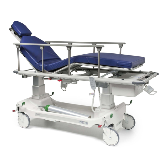
Page 11: Features (Shown In Illustration Of 5E8Eyxst Below)
Built-In Oxygen Tank Holder Patient Pendant (Located in Base Cover on Warning Label Patient’s Right Side) See WARNINGS D, E and H Fowler Backrest Quick Drop Handle See WARNING F WARNINGS — CAUTIONS AND PROPER OPERATION (See List on Previous Page) 5E8-IN-INS-LAB-RevB19... -
Page 12: Braking And Steering Operation (All Models)
Release the steering lock by depressing the red pedal at any corner of the unit until the pedal is in a horizontal position (Figure 3-2). All four casters should then rotate and swivel freely, and / or the optional fifth wheel will retract. 5E8-IN-INS-LAB-RevB19... -
Page 13: Stretcher Top Height Adjustment (578 Hydraulic Models)
3.4.4 Reverse Trendelenburg Adjustment Place the unit at maximum height (see Height Adjustment above). Press down on the release pedal nearest the foot end (Figure 3-7) until Figure 3-6 desired position is reached, then remove pressure. Figure 3-7 5E8-IN-INS-LAB-RevB19... -
Page 14: Backrest / Knee Flex Operation (578 Hydraulic Models)
To lower the backrest or knee flex, flip the crank handle upward and rotate the crank handle counterclockwise (Figure 3-8). When the desired position is reached, stop the rotating motion and return the crank handle to its original position (Figure 3-9). Figure 3-9 5E8-IN-INS-LAB-RevB19... -
Page 15: Electric Control Locations (5D8 And 5E8 Models)
ELECTRIC CONTROL LOCATIONS (5D8 AND 5E8 MODELS) 3.6.1 Nurse Control Panel To access the nurse control panel pull out on the handle located at the head end of the unit, Figure 3-10 under the top. (Figures 3-10 and 3-11). 3.6.2 Patient Pendant Control... -
Page 16: Emergency Electric Backrest Override
3.6.6 Charge Indicator Light The charge indicator light is positioned in the left bottom corner of the nurse control panel at row 3, column 1 (Figure 3-15), and will illuminate whenever the unit is plugged in to the wall. 5E8-IN-INS-LAB-RevB19... -
Page 17: Stretcher Top Adjustment (5E8 And 5D8 Electric Models)
STRETCHER TOP ADJUSTMENT (5E8 AND 5D8 ELECTRIC MODELS) WARNING: The lockout panel deactivates both the patient pendant and the control panel. 3.7.1 Hand Pendant Functions Figure 3-16 Foot Section Adjustment Raising: Press the first button on the second row of buttons on the pendant (Figure 3-16). Hold until the desired angle is achieved. -
Page 18: Trendelenburg Adjustment (Hand Pendant)
Press and hold the third button on the top row. At the same time, press and hold the UP or DOWN arrow button which corresponds to the desired direction of travel (Figure 3-24) until the preferred height is achieved. Figure 3-24 5E8-IN-INS-LAB-RevB19... -
Page 19: Trendelenburg Adjustment
To initiate neutral return, press and hold the second button from the right on the second row (row 2, column 2). At the same time, press and hold the UP or DOWN arrow button which corresponds to the desired direction of travel (Figure 3-27). 5E8-IN-INS-LAB-RevB19... -
Page 20: Lockout
Press the Lockout Button simultaneously with the third button on the top row (Figure 3-31) of the control panel. Trendelenburg Lockout Figure 3-31 Press the Lockout Button simultaneously with the fourth button on the top row (Figure 3-32) of the control panel. Figure 3-32 5E8-IN-INS-LAB-RevB19... -
Page 21: Patient Rail Operation (All Models)
Figure 3-35 the way down. WARNING: When lowering the rails, ensure patient and caregiver body and extremities are clear of pinch points before operating the rail (Figure 3-35). WARNING: Ensure both rails are in upright locked position before leaving patient. 5E8-IN-INS-LAB-RevB19... -
Page 22: Eye Headrest (All Models)
Rotate the knob counterclockwise to adjust the height of the head rest (Figure 3-41). Figure 3-39 IMPORTANT After understanding which knob creates which action, quick and smooth adjustment can be achieved by rotating the knobs simultaneously (Figure 3-42). Figure 3-40 Figure 3-41 Figure 3-42 5E8-IN-INS-LAB-RevB19... -
Page 23: Mounting The Wrist Rest
1. Support extended portion of IV Rod with one hand. 2. Rotate screw collar until loosened. 3. Lower IV Rod until desired height is HINGE achieved, then retighten screw collar. 4. Repeat process with second screw collar Figure 3-45 as required. 5E8-IN-INS-LAB-RevB19... -
Page 24: Troubleshooting Guide
Step 3: (After 4/11/00) replace (2) batteries with VISION CP1213, 12V 1.3 Ah (Hausted P/N 075759 – 2 required, for CB-12 controllers). Step 4: Ensure battery connector is in place on left side of batteries. Step 5: Replace cover. 5E8-IN-INS-LAB-RevB19... -
Page 25: Preventive Maintenance For The User
Info: For more detailed information, please contact GF Health Products, Inc. at 1.770.368.4700. Info: In addition to the User Preventive Maintenance, a more detailed Preventive Maintenance Program is also required to keep the equipment in good working order. This Preventive Maintenance Program is found on our website, at www.Hausted.com. 5E8-IN-INS-LAB-RevB19... -
Page 26: Optional Accessories
WARNING: It is recommended that only accessories approved by GF Health Products, Inc. be used with this device. The use of accessories, transducers, and cables other than those specified by the manufacturer may result in increased emissions or decreased immunity of the Hausted equipment. Info: To order accessories, or for more detailed information on accessories, please contact GF Health Products, Inc. at 1.770.368.4700. 5E8-IN-INS-LAB-RevB19... -
Page 27: Gf Health Products, Inc. Limited Warranty For Hausted Brand Product Line Outside The U.s
For additional information on this Hausted product or this warranty, please contact a Graham-Field authorized Distributor. NOTES: 1) Additional terms and conditions may apply. -
Page 28: Disposal And Key To Symbols
The following symbols are used on Hausted product labels. Protective Earth Manufacturer Earth Ground Keep Dry General Warning Sign Fragile, Handle with Care CE Mark Electrical and Electronic Equipment Consult Instructions for Use European Authorized Caution Representative www.hausted.com www.grahamfield.com 5E8-IN-INS-LAB-RevB19... -
Page 29: Appendix
15 cm. If the shows that the RISK ANALYSIS ME EQUIPMENT ME SYSTEM will be used closer than 15 cm to sources of power frequency magnetic field, the shall be IMMUNITY TEST LEVEL adjusted as appropriate for the minimum expected distance. 5E8-IN-INS-LAB-RevB19... -
Page 30: Enclosure Port Immunity To Rf Wireless Communications Equipment
4, 25; UMTS Bluetooth, Pulse WLAN, 2 400 – modulation 2 450 802.11 b/g/n, 2 570 RFID 2450, 217 Hz LTE Band 7 5 240 Pulse 5 100 – WLAN 802.11 modulation 5 500 5 800 217 Hz 5 785 5E8-IN-INS-LAB-RevB19... -
Page 31: Input Ac Power Port
250/300 cycles at any angle and at all phases at the same time (if applicable). M E EQUIPMENT with battery backup shall resume line power operation after the test. For SYSTEMS ME EQUIPMENT with input current not exceeding 16 A, all phases shall be interrupted simultaneously. ME SYSTEMS RATED 5E8-IN-INS-LAB-RevB19... -
Page 32: Patient Coupling Port
Discharges shall be applied with no connection to an artificial hand and no connection to simulation. PATIENT simulation may be connected after the test as needed in order to verify ATIENT BASIC SAFETY ESSENTIAL PERFORMANCE 5E8-IN-INS-LAB-RevB19... -
Page 33: Signal Input/Output Parts Port
5,4 MHz, 7 MHz to 7,3 MHz, 10,1 MHz to 10,15 MHz, 14 MHz to 14,2 MHz, 18,07 MHz to 18,17 MHz, 21,0 MHz to 21,4 MHz, 24,89 MHz to 24,99 MHz, 28,0 MHz to 29,7 MHz and 50,0 MHz to 54,0 MHz. 5E8-IN-INS-LAB-RevB19... -
Page 34: Recommended Separation Distances Between Portable And Mobile Rf Communications Equipment And Hausted Stretchers
(W) according to the transmitter manufacturer. NOTE 1: At 80 MHz and 800 MHz, the higher frequency range applies. NOTE 2: These guidelines may not apply in all situations. Electromagnetic propagation is affected by absorption and reflection from structures, objects, and people. NOTES TO SECTION 9 1. 60601-1-2 © IEC:2014 5E8-IN-INS-LAB-RevB19... -
Page 35: Index
Reverse Trendelenburg adjustment, hydraulic models 13 Disposal 28 Safety statements, significance of 5 Electrical specifications (5D8) 9 Service information 4 Electrical specifications (5E8)) 9 Stretcher top adjustment, electric models 17 Electric control locations 13, 15 Surgi-stretcher specifications 9 Electric powered stretchers, troubleshooting guide 24... - Page 36 The most current and complete product information can be found on our website. www.grahamfield.com © 2014, GF Health Products, Inc. All Rights Reserved. Hausted is a trademark of GF Health Products, Inc., One Graham-Field Way, Atlanta GA 30340-3140 GF Health Products, Inc. is an ISO 13485 Certified Company.
Need help?
Do you have a question about the 5E8 and is the answer not in the manual?
Questions and answers