Durr Dental Duo Tandem Installation And Operating Instructions Manual
Hide thumbs
Also See for Duo Tandem:
- Installation and operating instructions manual (44 pages) ,
- Installation and operating instructions manual (40 pages) ,
- Installation and operating instructions manual (44 pages)

Related Manuals for Durr Dental Duo Tandem


Summary of Contents for Durr Dental Duo Tandem
- Page 1 Duo Tandem / Quattro Tandem Installation and operating instructions 0297 4252100034L02 *4252100034L02*...
- Page 3 ..... . Duo Tandem ....
-
Page 4: Table Of Contents
Contents Usage 13 Operation ..... . . 13.1 Operating panel ....13.2 Switching the unit on/off . - Page 5 These installation and operating instructions Observe the operating instructions. apply to: Duo Tandem Order number: 4152-54; 4252-54; 4152100008; Disconnect all power from the unit. 4252100027 Quattro Tandem Order number: 4642-54;...
- Page 6 Important information Copyright information Safety All circuits, processes, names, software pro- Dürr Dental has designed and constructed this grams and units mentioned in this document are unit so that when used properly and for the inten- protected by copyright. ded purpose it does not pose any danger to The Installation and Operating Instructions must people or property.
- Page 7 Important information Electrical safety WARNING Observe and comply with all the relevant elec- ❯ Risk of explosion due to ignition of trical safety regulations when working on the combustible materials unit. Do not operate the unit in any rooms in ❯...
- Page 8 Important information 2.10 Disposal The unit must be disposed of properly. Within the European Union, the unit must be disposed of in accordance with EU Directive 2012/19/EU (WEEE). If you have any questions about the correct ❯ disposal of parts, please contact your dental trade supplier.
- Page 9 Virus bacteria filter ....1650100172 Duo Tandem 400 V, 3~, with 1 com- Sintered filter ....1650-101-00 pressor unit and membrane drying unit .
- Page 10 Product description Technical data Duo Tandem Electrical data 4152-54 4252-54 Rated voltage Mains frequency Nominal current at 8 bar (0.8 MPa) Type of protection IP 21 IP 21 Mains fuses * Circuit breaker fuse characteristics B, C or D in acc. with EN 60898-1...
- Page 11 Product description Network connection LAN technology Ethernet Standard IEEE 802.3u Data rate Mbit/s Connector RJ45 Type of connection Auto MDI-X Cable type ³ CAT5 Ambient conditions during storage and transport Temperature °C -10 to +55 Relative humidity max. 95 Ambient conditions during operation Temperature °C +10 to +40...
- Page 12 Product description Duo Tandem Electrical data 4152100008 4252100027 Rated voltage 230, 1~ 230, 1~ Mains frequency Nominal current at 8 bar (0.8 MPa) 12.2 14.3 Type of protection IP 21 IP 21 Mains fuses * Max. permissible mains impedance in accordance with EN 61000-3-11** 0.22...
- Page 13 Product description Filter mesh size Coalescence filter µm 0.01 Network connection LAN technology Ethernet Standard IEEE 802.3u Data rate Mbit/s Connector RJ45 Type of connection Auto MDI-X ³ CAT5 Cable type Ambient conditions during storage and transport Temperature °C -10 to +55 Relative humidity max.
- Page 14 Product description Quattro Tandem Electrical data 4642-54 4682-54 4682100001 Rated voltage Mains frequency Nominal current at 8 bar (0.8 MPa) Type of protection IP 21 IP 21 Mains fuses * Max. permissible mains impedance in £ 0.24 £ 0.18 accordance with EN 61000‑3‑11 ** Circuit breaker fuse characteristics B, C or D in acc.
- Page 15 Product description Network connection LAN technology Ethernet Standard IEEE 802.3u Data rate Mbit/s Connector RJ45 Type of connection Auto MDI-X Cable type ³ CAT5 Ambient conditions during storage and transport Temperature °C -10 to +55 Relative humidity max. 95 Ambient conditions during operation Temperature °C +10 to +40...
- Page 16 Product description Distance between rubber feet Distances between the rubber feet for different pressure vessel volumes: Compressor unit type plate Membrane drying unit The type plate of the membrane drying unit is located on the side of the membrane drying unit. a (cm) b (cm) 20 l...
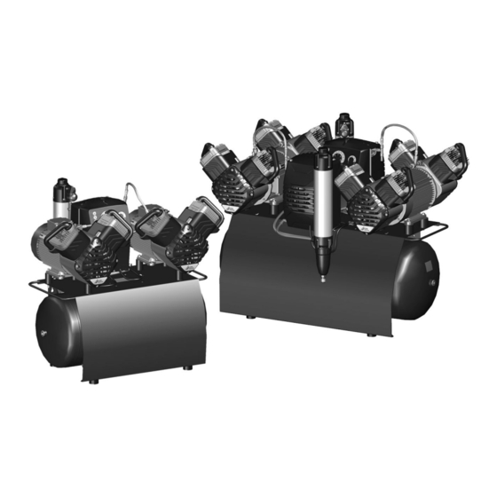
- Page 17 Product description Operation Duo Tandem / Quattro Tandem Fine or virus bacteria filter Air intake filter Membrane drying unit Sintered or coalescence filter Safety valve Pressure gauge/display Compressed air connection (quick release coupling) Collector tray Controller Intake connector Compressor unit...
- Page 18 Product description Start-up behaviour On compressors with an electronic controller, the compressor units are switched on with a time delay. The time delay depends on the operating mode selected on the controller. Operating mode: – Eco: 180 s – Balanced: 60 s –...
- Page 19 Assembly Assembly ≥ 40 °C Requirements The unit must not be set up or operated within the vicinity of the patients (within a radius of 1.5 m). The unit can be installed either at the same level as the surgery room or on a floor below (e.g. cel- lar).
- Page 20 WARNING Risk of explosion of the pressure tank The transport locks only need to be and pressure hoses removed on the Duo Tandem, as the compressor units are delivered separately The pressure tank and the pressure ❯ for the Quattro Tandem.
- Page 21 Assembly Place the compressor units on the vibration Connect the compressor unit with the mem- ❯ ❯ reducers with the motor terminal box facing brane drying unit via the pressure hose. towards the control. Warning – risk of dangerous electric vol- Attach the compressor unit with the lock wash- ❯...
- Page 22 Assembly Establishing the compressed When routeing the cables, maintain the air connection correct gaps between control cables and supply cables. The supplied flexible pressure hose Guide the cables of the compressor units ❯ between the pipe system and the com- through the strain relief and fasten.
- Page 23 Assembly Network connection Purpose of the network connection The network connection is used to exchange information or control signals between the unit and a software installed on a computer, in order to, e. g.: – Display parameters – Select operating modes –...
- Page 24 Assembly Make sure that none of the electrical cables MAIN ❯ leading to the unit are under any mechanical tension. Before initial start-up check that the mains sup- ❯ ply voltage and the voltage stated on the type plate match (see also "4. Technical data"). Establishing the electrical connections DANGER Risk of electric shock due to defective...
- Page 25 Assembly Working in controller of the compressor to be Commissioning ❯ operated as the secondary compressor, move In many countries technical medical prod- the switch S1 to the left-hand position (auxiliary ucts and electrical devices are subject to control). regular checks at set intervals. The owner must be instructed accordingly.
- Page 26 Assembly Fill the pressure tank to the cut-off pressure. Draining the condensation ❯ water WARNING During transport, condensation water can accu- Risk of damage to the safety valve mulate in the pressure tank due to changes in Risk of explosion of the pressure tank temperature.
- Page 27 Assembly Check the firewall and release the ports, if ❯ applicable. Network protocols and ports Port Purpose Service 45123 UDP, Unit recognition and 45124 UDP configuration 1900 UDP Service detection SSDP / UPnP 502 TCP Unit data Event protocol data Syslog 22 TCP Diagnosis...
- Page 28 Assembly 10 Adjustment options 10.1 Adjustment of the switch- on/cut off pressure WARNING Risk of explosion of the pressure ves- The pressure vessels used in the com- pressors are designed to withstand continuous pressure changes of 2 bar and can be used continuously under these pressure changes.
- Page 29 Assembly 11 Controller 11.1 3/N/PE AC 400 V layout PE L2 X101 F1 F2 F3 F5 F6 Fuse T10AH/T12AH* Fuse T10AH/T12AH* Fuse T10AH/T12AH* Fuse T10AH/T12AH* Fuse T10AH/T12AH* Fuse T10AH/T12AH* Fuse T1.6AH Status indicator LED for temperature sensor, compressor unit 1 Status indicator LED for temperature sensor, compressor unit 1 Status indicator LED for temperature sensor, compressor unit 1 Status indicator LED for temperature sensor, compressor unit 2...
- Page 30 Assembly Cooling fan motor, membrane drying unit 1 Cooling fan motor, membrane drying unit 2 (Quattro Tandem only) Fan motor, compressor cabinet (Duo Tandem only) Fan motor, compressor cabinet (Duo Tandem only) Switch, main controller/auxiliary controller Temperature sensor, compressor unit 1...
- Page 31 Assembly 11.2 1/N/PE AC 230 V layout X101 F4 F5 F2 F3 PE L 1/N/PE AC 230V Fuse T1.6AH Fuse T10AH Fuse T10AH Fuse T10AH Fuse T10AH Fuse T0.4AH Compressor unit 1 Compressor unit 2 Cooling fan motor, membrane drying unit Switch, main controller/auxiliary controller Solenoid valve 1 Solenoid valve 2...
- Page 32 Assembly 12 Media plan 12.1 3/N/PE AC 400 V layout Compressor unit Cooler Separator Dryer Non-return valve Pressure tank Compressed air connection 12.2 1/N/PE AC 230 V layout Compressor unit Solenoid valve Non-return valve Cooler Separator Dryer Pressure tank Compressed air connection 4252100034L02 2105V002...
-
Page 33: Operation
Usage Pressure range Usage The pressure is displayed and can be adjusted in this area. The pressure is displayed via: 13 Operation 1. LED (£ 4.5 bar): Lights up continuously, even with a pressure Prior to working on the unit or in case of <... -
Page 34: Normal Operation
Usage 13.3 Normal operation – Adjust the switch-on/cut off pressure. – Confirm the filter replacement. The unit is in normal operation as soon as the – Deactivate the emergency mode. plug is inserted in the power outlet. The com- pressor runs until the cut off pressure is reached. In standby mode, also press the service key ❯... -
Page 35: Maintenance
Usage 14 Maintenance Prior to working on the unit or in case of danger, disconnect it from the mains. WARNING Risk of infection due to burst filters Particles enter the compressed air network and can therefore enter the mouth of the patient. Replace filters in accordance with the maintenance schedule. - Page 36 Usage Information about replacement parts is available from the portal for authorised specialist dealers www.duerrdental.net 4252100034L02 2105V002...
-
Page 37: Changing The Filter
Usage Replacing the fine or virus bacteria filter 14.3 Changing the filter Unscrew and remove the filter cover. ❯ Remove the filter. ❯ NOTICE Insert a new filter. ❯ Shortened service life, bad air quality, Replace the filter cover and close. ❯... -
Page 38: Taking Out Of Use
Usage Press for at least 2 seconds. The unit is 15 Taking out of use ❯ now in setup mode. LED is flashing. 15.1 Taking the unit out of use Press to confirm filter replacement. ❯ Resetting the unit to standby mode: Wear ear protectors. -
Page 39: Storage Of The Unit
Usage At maximum tank pressure, slowly open the Close condensate drain valves on the drying ❯ ❯ condensate drain valve. units. Once the start-up pressure has been reached the Disconnect the compressor from the pipe sys- ❯ compressor unit will switch on. tem. -
Page 40: Troubleshooting
Troubleshooting Troubleshooting 16 Tips for operators and service technicians Any repairs exceeding routine maintenance may only be carried out by qualified personnel or our service. Prior to working on the unit or in case of danger, disconnect it from the mains. Error Possible cause Remedy... - Page 41 Troubleshooting Error Possible cause Remedy Compressor does not switch Excessive air extraction Check air requirements and ❯ dimensioning of the compres- off or has difficulty reaching the cut off pressure sor. Air intake filter dirty Replace the air intake filter. ❯...
-
Page 42: Appendix
Appendix Appendix 17 Handover record This document confirms that a qualified handover of the medical device has taken place and that appropriate instructions have been provided for it. This must be carried out by a qualified adviser for the medical device, who will instruct you in the proper handling and operation of the medical device. Product name Order number (REF) Serial number (SN) - Page 43 Appendix 4252100034L02 2105V002...
- Page 48 Hersteller / Manufacturer: DÜRR DENTAL SE Höpfigheimer Str. 17 74321 Bietigheim-Bissingen Germany Fon: +49 7142 705-0 www.duerrdental.com info@duerrdental.com...
Need help?
Do you have a question about the Duo Tandem and is the answer not in the manual?
Questions and answers