
Related Manuals for Renogy MPPT20CC


Summary of Contents for Renogy MPPT20CC
- Page 1 MPPT20CC RENOGY 20A Maximum Power Point Tracking Solar Charge Controller Manual 14288 Central Ave., Suite A Chino, CA 91710 1-800-330-8678...
-
Page 2: Table Of Contents
Contents 1. Important Safety Information 2. General Information 2.1 Overview 2.2 Optional Accessories 3. Installation Instructions 3.1 General Installation Notes 3.2 Mounting 3.3 Wiring 4. Operation 4.1 MPPT Technology 4.2 Battery Charging Information 4.3 LED Indications 4.4 Setting Operation 5. Protections, Troubleshooting and Maintenance 5.1 Protection 5.2 Troubleshooting 5.3 Maintenance... -
Page 3: Important Safety Information
• Read all of the instructions and cautions in the manual before beginning installation. • There are no user serviceable parts inside the MPPT20CC. Do not disassemble or attempt to repair the controller. • Disconnect the solar module and fuse/breakers near to battery before installing or adjusting the MPPT20CC. -
Page 4: General Information
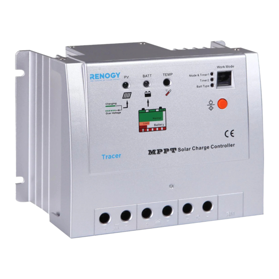
The comprehensive self-diagnostics and electronic protection functions can prevent damage from installation mistakes or system faults. In addition, the MPPT20CC controller has a RJ45 interface to allow communication with a meter for remote monitoring. The MPPT20CC has the following features: •... - Page 5 Description of MPPT20CC controller: RJ45 Figure 2-1 MPPT20CC Characteristics 1. Charging Status LED indicator 2. Battery Status LED indicator 3. Temperature Sensor 4. Setting Indicators 5. LED Digital Display the load work mode and status. 6. Setting Button (in manual mode used for load ON/OFF) 7.
-
Page 6: Optional Accessories
The meter can be flush mounted in a wall or surface mounted using the mounting frame (included). The MT-5 is supplied with 2 m of cable and a mounting frame. The MT-5 connects to the RJ45 port on the MPPT20CC. ... -
Page 7: Installation Instructions
If mounted in an enclosure, ventilation is highly recommended. WARNING: Risk of explosion! Never install the MPPT20CC in a sealed enclose with flooded batteries! Do not install in a confined area where battery gas can accumulate. -
Page 8: Wiring
Step 2: Check for Clearance Place the MPPT20CC in the location where it will be mounted. Verify that there is sufficient room to run wires and that there is sufficient room above and below the controller for airflow. - Page 9 Step 2: Load Wiring The MPPT20CC load output can connect DC electronic devices of which the rated voltage is the same as the battery. MPPT20CC will provide battery the voltage to the loads. See Section 4.4 Setting Operation for more details about the load control.
- Page 10 Verify that all power terminals are tightened. Step 6: Confirm Power-up When battery power is applied and the MPPT20CC powers up, the battery led indicator will be green. If the MPPT20CC does not power-up or battery status LEDs error exists, refer to Section 5 “Troubleshooting”...
-
Page 11: Operation
MPPT20CC does not create current! Rest assured that the power into the charge controller is the same as the power out of the MPPT20CC. Since power is the product of voltage and current (Volts × Amps), the following is true*: •... - Page 12 The greater the difference between battery voltage and the Vmp of the module, the more energy is wasted. MPPT20CC MPPT technology will always operate at the Vmp resulting in less wasted energy compared to traditional controllers.
-
Page 13: Battery Charging Information
Float Charge After the Boost voltage stage, MPPT20CC will reduce the battery voltage to float voltage set point. When the battery is fully recharged, there will be no more chemical reactions and all the charge current transforms into heat and gas at this point. -
Page 14: Led Indications
Equalize WARNING: Risk of explosion! Equalizing flooded batteries can produce explosive gases, so a well-ventilated battery box is necessary. NOTE: Equipment damage! Equalization may increase battery voltage to a level damaging to sensitive DC loads. Ensure that all load allowable input voltages are greater than the equalizing charging set point voltage. - Page 15 Charging Indicator The green LED indicator will turn on whenever sunlight is available for battery charging. Under normal charging conditions, the green charging LED will stay on at all times. The charging LED indicator flashes when the battery reaches over- voltage.
-
Page 16: Setting Operation
Load indicator When the load amperage is 1.25 times of rated current for 60 seconds, 1.5 times of rated current for 5 seconds (overload), or there is a load short circuit, the Battery LED indicator will be flashing RED. Please refer to section 5 for troubleshooting. - Page 17 on the load after 10 minutes delay for several hours which users set on the timer. The timer setting operation is referred to as “Load Work Mode Setting”. 3. Test Mode It is used to test the system and the same as Dusk to Dawn. But there is no 10- minute delay when controller recognizes the starting voltage.
- Page 18 Timer 1 LED Digital No. Disable Dusk-to-Dawn, Load will be on all night Load will be on for 1 hour after a ten minute delay since sunset Load will be on for 2 hours after a ten minute delay since sunset Load will be on for 3 hours after a ten minute delay since sunset Load will be on for 4 hours after a ten minute delay since sunset Load will be on for 5 hours after a ten minute delay since sunset...
- Page 19 Battery Type Setting When the Battery setting indicator is on, press the “Setting” button and hold on 5 seconds until the battery type LED turns on. The led will be flashing. Continue to hold and the number will repeat from 1 to 3, and stop pressing until the desired number appears according to the following setting table: Battery type Digital display...
-
Page 20: Protections, Troubleshooting And Maintenance
5. Protections, Troubleshooting and Maintenance 5.1 Protection PV Array Short Circuit If PV array short circuit occurs, clear it to resume normal operation. PV Overvoltage If PV Overvoltage occurs, the array will remain disconnected until the voltage falls safely below the maximum rating. PV Overcurrent If PV Overcurrent occurs, the array will be disconnected automatically. -
Page 21: Troubleshooting
High Voltage Transients PV is protected against high voltage transients. In lightning prone areas, additional external suppression is recommended. 5.2 Troubleshooting Faults Possible reasons Troubleshooting Charging LED indicator off during PV array disconnection Check that PV and battery wire daytime when panels are in direct connections are correct and tight. -
Page 22: Maintenance
5.3 Maintenance The following inspections and maintenance tasks are recommended at least two times per year for best controller performance: • Check that the controller is securely mounted in a clean and dry environment. • Check that the airflow and ventilation around the controller is not blocked. Clear all dirt or fragments on the heat sink. -
Page 23: Warranty
6. Warranty The MPPT20CC charge controller is warranted to be free from defects for a period of ONE (1) year from the date of shipment to the original end user. We will, at our option, repair or replace any such defective products. -
Page 24: Technical Specifications
7. Technical Specifications Electrical Parameters Description Parameter Nominal System Voltage 12VDC/24VDC Auto recognition Rated Charge Current Rated Load Current Maximum Battery Voltage Max. Solar Input Voltage* 100VDC Max. PV Input Power 260W (12V), 520W (24V) Self-consumption** <10mA (24V) Charge Circuit Voltage Drop ≤... - Page 25 Threshold Voltage Description Parameter NTTV (Night Time Threshold Voltage) 5V; x2/24V DTTV (Day Time Threshold Voltage) 6V; x2/24V Table 7-3 Threshold Voltages Temperature Compensation Description Parameter Temperature Compensation Coefficient -30mV/°C/12V (25°C ref) (TEMPCO)* Table 7-4 Temperature Compensation *Compensation of equalize, boost, float and low voltage disconnect voltage Environmental Parameters Environmental Parameter...
- Page 26 PV Power – Conversion Efficiency Curve Illumination Intensity: 1000W/m Temperature: 25°C 1. Solar Module MPP Voltage (17V) / Nominal System Voltage (12V) 2. Solar Module MPP Voltage (34V) / Nominal System Voltage (12V) ...
- Page 27 3. Solar Module MPP Voltage (68V) / Nominal System Voltage (12V) 4. Solar Module MPP Voltage (34V) / Nominal System Voltage (24V) ...
- Page 28 5. Solar Module MPP Voltage (68V) / Nominal System Voltage (24V) ...
- Page 29 MPPT20CC Dimensions (mm) ...
Need help?
Do you have a question about the MPPT20CC and is the answer not in the manual?
Questions and answers