
Related Manuals for Renogy Rover 40A


Summary of Contents for Renogy Rover 40A
- Page 1 Rover Series Rover 20A | 40A Maximum Power Point Tracking Solar Charge Controller 2775 E. Philadelphia St., Ontario, CA 91761 1-800-330-8678 Version 1.0...
- Page 2 Important Safety Instructions Please save these instructions. This manual contains important safety, installation, and operating instructions for the charge controller. The following symbols are used throughout the manual to indicate potentially dangerous conditions or important safety information. WARNING: Indicates a potentially dangerous condition. Use extreme caution when performing this task.
- Page 3 Explosive battery gases may be present while charging. Be certain there is enough ventilation to release the gases. Be careful when working with large lead acid batteries. Wear eye protection and have fresh water available in case there is contact with the battery acid. ...
-
Page 4: Table Of Contents
Table of Contents General Information .................. 4 Additional Components ................7 Identification of Parts ................8 Operation ....................13 LED Indicators ..................17 Rover Protections ................... 19 System Status Troubleshooting ............20 Maintenance .................... 21 Fusing ...................... 21 Technical Specifications ................ 22 Electrical Parameters ................ -
Page 5: General Information
General Information The Rover Series charge controllers are suitable for various off-grid solar applications. It protects the battery from being over-charged by the solar modules and over-discharged by the loads. The controller features a smart tracking algorithm that maximizes the energy from the solar PV module(s) and charge the battery. - Page 6 Therefore, assuming 100% efficiency: Power In = Power Out Volts In * Amps In = Volts out * Amps out Although MPPT controllers are not 100% efficient, they are very close at about 92-95% efficient. Therefore, when the user has a solar system whose Vmp is greater than the battery bank voltage, then that potential difference is proportional to the current boost.
- Page 7 Four Charging Stages The Rover MPPT charge controller has a 4-stage battery charging algorithm for a rapid, efficient, and safe battery charging. They include: Bulk Charge, Boost Charge, Float Charge, and Equalization*. Bulk Charge: This algorithm is used for day to day charging. It uses 100% of available solar power to recharge the battery and is equivalent to constant current.
-
Page 8: Additional Components
chemical reactions and all the charge current would turn into heat or gas. Because of this, the charge controller will reduce the voltage charge to smaller quantity, while lightly charging the battery. The purpose for this is to offset the power consumption while maintaining a full battery storage capacity. -
Page 9: Identification Of Parts
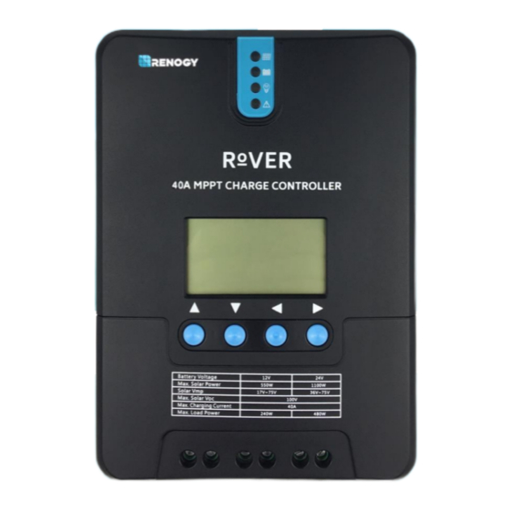
Through the software, users could customize their charge Figure 1 parameters and other settings. Download the PC software through Renogy’s website under the “Downloads” section. NOTE: PC Communication requires the USB be connected at all times. Wireless capability not available. - Page 10 Key Parts 1. PV LED Indicator 2. Battery LED Indicator 3. Load LED Indicator 4. System Error LED Indicator 5. LCD Screen 6. Operating Keys 7. Mounting Holes 8. Remote Temperature Sensor Port (optional accessory) 9. PV Terminals 10. Battery Terminals 11.
- Page 11 INVERTER BATTERY CHARGER HIGH AMP DRAWING DEVICE CAUTION: Do not over tighten the screw terminals. This could potentially break the piece that holds the wire to the charge controller. CAUTION: Refer to the technical specifications for max wire sizes on the controller and for the maximum amperage going through wires.
- Page 12 Load (optional) Solar Panels...
- Page 13 PC communication (optional) Temperature Sensor (optional, not polarity sensitive) Mounting Recommendations WARNING: Never install the controller in a sealed enclosure with flooded batteries. Gas can accumulate and there is a risk of explosion. 1. Choose Mounting Location—place the controller on a vertical surface protected from direct sunlight, high temperatures, and water.
-
Page 14: Operation
3. Mark Holes 4. Drill Holes 5. Secure the charge controller. Operation Rover is very simple to use. Simply connect the batteries, and the controller will automatically determine the battery voltage. The controller comes equipped with an LCD screen and 4 buttons to maneuver though the menus. Startup Interface... - Page 15 Main Display Solar Panel Voltage Main Screen Charging Current Battery Voltage Battery Capacity Error Code Accumulated AH Load Current Ambient Temperature Discharged AH Load mode...
- Page 16 Page Up/ Increase parameter value / Page Down/ Decrease parameter value / - Return to the previous menu Enter sub menu/ save parameter value/ ENTER/ turn load on or off in manual mode Programming Parameters Battery type System voltage Equalizing voltage...
- Page 17 Programming Load Terminal 1. This screen is displaying the current Load Mode. 2. To enter screen 2 press and hold the Enter button. This screen will allow you to change the load mode. 3. To change the load mode press the up or down button. 4.
-
Page 18: Led Indicators
LCD Indicators LED Indicators ---PV array ○ Indicating the controller's current charging mode. indicator Indicating the battery's current ---BAT indicator ○ state. ---LOAD indicator Indicating the loads' On/ Off state. ○ ---ERROR ○ Indicating whether the controller is functioning normally. indicator... - Page 19 PV Indicator (1) Status White Solid The PV system is charging the battery bank White Slow The Controller is undergoing boost stage Flashing White Single The Controller is undergoing float stage Flashing White Fast The Controller is undergoing equalization stage Flashing White The PV system is charging the battery bank at a slow rate.
-
Page 20: Rover Protections
Rover Protections Protection Behavior PV Array Short When PV shot circuit occurs, the controller will stop charging. Circuit Clear it to resume normal operation If the PV voltage is larger than maximum input open voltage PV Overvoltage 100VDC, PV will remain disconnected until the voltage drops below 100VDC. -
Page 21: System Status Troubleshooting
System Status Troubleshooting PV indicator Troubleshoot Ensure that the PV wires are correctly and tightly secured inside the Off during charge controller PV terminals. Use a multi-meter to make sure the daylight poles are correctly connected to the charge controller. BATT Indicator Troubleshoot Disconnect loads, if any, and let the PV modules charge the battery... -
Page 22: Maintenance
Maintenance WARNING: Risk of Electric Shock! Make sure that all power is turned off before touching the terminals on the charge controller. For best controller performance, it is recommended that these tasks be performed from time to time. 1. Check that controller is mounted in a clean, dry, and ventilated area. 2. -
Page 23: Technical Specifications
Technical Specifications Electrical Parameters Model ROV-20 ROV-40 Nominal system voltage 12V/24V Auto Recognition Rated Battery Current Rated Load Current Max. PV Input Short Current Max. Battery Voltage Max Solar Input Voltage 100 VDC Max. Solar Input Power 12V @ 260W 12V @ 520W 24V @ 520W 24V @ 1040W... -
Page 24: Mechanical Parameters
Discharging Limit 10.6 V 10.6 V 10.6 V 9-17V Voltage Equalization ----- 2 hours 2 hours 0-10 Hrs. Duration Boost Duration 2 hours 2 hours 2 hours 1-10 Hrs. **Parameters are multiplied by 2 for 24V systems. Environment Parameters Model ROV-20 ROV-40 Working... -
Page 25: Rover: Pv Power - Conversion Efficiency Curves
ROVER: PV Power – Conversion Efficiency Curves Illumination Intensity: 1000W/ m Temp 25 1. 12 Volt System Conversion Efficiency MPPT 12V conversion efficiency (12V battery) Output power(W) 2. 24 Volt System Conversion Efficiency MPPT 24V conversion efficiency (24V battery) Output power(W)... -
Page 26: Dimensions
Dimensions ROV-20 Product dimensions: 210*151*59.5mm Hole positions: 154*131mm Hole diameter: Ø 3mm Maximum Wire Gauge 10 AWG NOTE: Dimensions in millimeters (mm) - Page 27 ROV-40 Product dimensions: 238*173*72.5mm Hole positions: 180*147mm Hole diameter: Ø 3mm Maximum Wire Gauge 8 AWG NOTE: Dimensions in millimeters (mm) Renogy reserves the right to change the contents of this manual without notice. Revision: 2/21/2017...
Need help?
Do you have a question about the Rover 40A and is the answer not in the manual?
Questions and answers
How to change float parameters on a Rover 40amp MPPT?
To change the float parameters on a Renogy Rover 40A MPPT, use the Renogy DC Home App. Ensure that the correct battery type is selected, and adjust the charging parameters, including the float voltage, according to the battery manufacturer's recommendations. For 24V systems, multiply the 12V parameters by 2.
This answer is automatically generated
I need to reconnect cables from solar and Battery but unclear which holes are negative and positive can you give me a diagram of what each of the connector holes connect to? I’m concerned about connecting the wrong ones first.