Renogy RCC30REGO Manual
- User manual (42 pages) ,
- Quick start manual (18 pages)
Advertisement
General Information
Symbols Used
The following symbols are used throughout the user manual to highlight important information.

Indicates a potentially hazardous condition that could result in personal injury or death.

Indicates a critical procedure for safe and proper installation and operation.

NOTE: Indicates an important step or tip for optimal performance.
Introduction
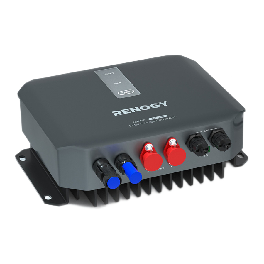
Renogy 12V/24V/36V/48V 30A MPPT Solar Charge Controller is an intelligent maximum power point tracking (MPPT) charge controller suitable for 12V, 24V, 36V, and 48V off-grid solar applications. Featuring a smart tracking algorithm, the charge controller maximizes the energy from the solar module(s) at more than 99.9% MPPT tracking efficiency and charges the battery at 97% conversion efficiency.
The plug-and-play solar and battery cables greatly simplify the installation. In addition, the built-in Bluetooth module allows you to configure and monitor your solar system by pairing the charge controller with your smartphone via the DC Home app (free of charge) and/or Renogy ONE Core (purchased separately).
The charging process has been optimized for long battery life and improved system performance. The comprehensive self-diagnostics and electronic protection functions can prevent damage from installation mistakes or system faults. The electronic protection functions include solar overvoltage, solar reverse polarity protection, battery overvoltage/undervoltage protection, over-temperature protection, and night charge protection.
Key Features
- High Battery Compatibility
The charge controller is compatible with 12V, 24V, 36V, and 48V AGM, SLD, flooded, gel, and lithium batteries as well as user-defined battery mode. - Auto Battery Voltage Detection
The charge controller detects 12V, 24V, 36V, and 48V DC system voltages for non-lithium batteries and programmability for lithium batteries. - Supreme Conversion Efficiency
The charge controller supports a maximum of 99.9% MPPT tracking efficiency and up to 97% conversion efficiency, mitigating the affect of cloudy days and damaged solar panels. - Full System Protection
The charge controller offers reverse polarity protection, overvoltage protection, short circuit protection, and reverse charging protection at night for solar panels. - Remote Power Monitoring Anywhere, Anytime
The built-in Bluetooth and RV-C communication module makes remote monitoring possible when the charge controller is paired with your smartphone via the DC Home app and Renogy ONE Core.
SKU
| Renogy 12V/24V/36V/48V 30A MPPT Solar Charge Controller | RCC30REGO |
Get to Know Renogy MPPT Solar Charge Controller
What's In the Box

Make sure that all accessories are complete and free of any signs of damage.
The accessories and product manual listed are crucial for the installation, excluding warranty information and any additional items. Please note that the package contents may vary depending on the specific product model.
Product Overview

System Setup

The wiring diagram only shows the key components in a typical DC-coupled off-grid energy storage system for the illustrative purpose. The wiring might be different depending on the system configuration. Additional safety devices, including disconnect switches, emergency stops, and rapid shutdown devices, might be required. Wire the system in accordance with the regulations at the installation site.
Wiring Setup

The Battery Temperature Sensor (BTS) Port can only be used with lead-acid batteries.
In this manual, the red cable represents the positive cable, and the gray cable represents the negative cable.
 Always connect the battery terminals before the solar panel terminals.
Preparation
Plan a Mounting Site
The charge controller requires adequate clearance for installation, wiring and ventilation. The minimum clearance is provided below. Ventilation is highly recommended if it is mounted in an enclosure. Select a proper mounting site to ensure the charge controller can be safely connected to the battery, and solar panels with the relevant cables.
To ensure good ventilation and optimal system performance, we recommend mounting the charge controller vertically (terminals down) on a wall or horizontally on the floor.

 Risk of explosion! Never install the charge controller in a sealed enclosure with flooded batteries! Do not install the charge controller in a confined area where battery gases can accumulate.
The charge controller should be installed on a flat surface protected from direct sunlight.
Keep the charge controller out of the reach of children and animals.
Do not expose the charge controller to flammable or harsh chemicals or vapors.
Make sure that the charge controller is installed in a place at ambient temperature from -31°F to 149°F (-35°C to 65°C). To ensure optimal working efficiency, it is recommended to keep the ambient temperature range from -31°F to 113°F (-35°C to 45°C).
Make sure that the charge controller is installed in an environment with relative humidity between 0% and 95% and no condensation.
If the charge controller is installed improperly on a boat, it may cause damage to components of the boat. Have the charge controller by a qualified electrician.
The charge controller should be as close to the battery as possible to avoid voltage drop due to long cables.
It is recommended that all cables (except communication cables) should not exceed 10 meters (32.8 feet) because excessively long cables result in a voltage drop. The communication cables should be shorter than 6 m (19.6 feet).
The cable specifications listed in the user manual account for critical, less than 3% voltage drop and may not account for all configurations.
Keep the charge controller away from EMI receptors such as TVs, radios, and other audio/visual electronics to prevent damage or interference to the equipment.
Recommended Tools

Prior to installing and configuring the charge controller, prepare the recommended tools, components, and accessories.
You can purchase Amphenol connectors from either renogy.com or arrow.com (with guaranted quality). Applicable models: C10-791435-1101 (for positive) and C10-791435-1102 (for negative). For details, contact the tech support team at renogy.com/contact-us or the customer service of the respective dealer.
How to Install the Amphenol Connectors

Check the Charge Controller
- Inspect the charge controller for any visible damage including cracks, dents, deformation, and other visible abnormalities. All connector contacts shall be clean and dry, free of dirt and corrosion.
![]()

Do not use the charge controller if there is any visible damage.
Do not puncture, drop, crush, penetrate, shake, strike, or step on the charge controller.
There are no serviceable parts in the charge controller. Do not open, dismantle, repair, tamper with, or modify the charge controller.
Confirm the polarities of the devices before connection. A reverse polarity contact can result in damage to the charge controller and other connected devices, thus voiding the warranty. Reverse polarity protection does not apply if the solar panel is connected to the charge controller before the battery.
Do not touch the connector contacts while the charge controller is in operation.
Wear proper protective equipment and use insulated tools during installation and operation. Do not wear jewelry or other metal objects when working on or around the charge controller.
Do not dispose of the charge controller as household waste. Comply with local, state, and federal laws and regulations and use recycling channels as required.
Check the Auxiliary Battery
Recommended Components & Accessories

Components and accessories marked with "*" are available on renogy.com.
To ensure optimal system performance, a 10 AWG cable should be no longer than 3 meters. Choose higher gauge cables for longer distances.
| Cable Length (ft)/(m) | 0 to 10 ft (0 to 3 m) | 11 to 20 ft (3 to 6 m) | 21 to 30 ft (6 to 9 m) |
| Recommended Cable Size | 10 AWG | 8 AWG to 10 AWG | 8 AWG |
The size of the fuse cable is consistent with that of the corresponding cable connecting to the output terminal of the charge controller.
- Inspect the battery for any visible damage including cracks, dents, deformation, and other visible abnormalities. All terminals shall be clean, free of dirt and corrosion, and dry.
The charge controller can only be connected to 12V, 24V, 36V or 48V deep-cycle gel-sealed lead-acid batteries (GEL), flooded lead-acid batteries (FLD), sealed lead-acid batteries (SLD/AGM) or lithium iron phosphate batteries (LI).
![]()
![warning]() Do not use the battery if there is any visible damage. Do not touch the exposed electrolyte or powder if the battery housing is damaged.
Do not use the battery if there is any visible damage. Do not touch the exposed electrolyte or powder if the battery housing is damaged.
![warning]() When being charged, the battery may give off explosive gas. Make sure there is good ventilation.
When being charged, the battery may give off explosive gas. Make sure there is good ventilation.
![warning]() Take care to use a high-capacity lead-acid battery. Be sure to wear protective goggles. If carelessly getting electrolyte in your eyes, flush your eyes with clean water immediately.
Take care to use a high-capacity lead-acid battery. Be sure to wear protective goggles. If carelessly getting electrolyte in your eyes, flush your eyes with clean water immediately.
![shock hazard]() Combine batteries in parallel or in series as needed. Prior to installing the charge controller, ensure all battery groups are installed properly.
Combine batteries in parallel or in series as needed. Prior to installing the charge controller, ensure all battery groups are installed properly.
![information]() Read the user manual of the battery in use carefully.
Read the user manual of the battery in use carefully. - Check system voltage for batteries connected in series or parallel.
This charge controller supports a maximum system voltage of 64V.
Read the battery user manual for battery voltage parameters, and calculate the voltage of the battery or battery pack system according to the formula to ensure that it does not exceed 64V.Battery or Battery Bank System Voltage Battery or Battery Bank System Voltage = System Voltage U Batteries in Series Batteries in Parallel System Voltage U: U1 + U2 + U3 System Voltage U: U1 = U2 = U3 ![warning]() Do not connect batteries rating higher than 64V to the charge controller. Doing so will damage the charge controller.
Do not connect batteries rating higher than 64V to the charge controller. Doing so will damage the charge controller.
![information]() In the formula, U represents the battery voltage, and 1, 2, or 3 represents the battery number respectively.
In the formula, U represents the battery voltage, and 1, 2, or 3 represents the battery number respectively. - Inspect the ANL Fuse (40A) for any visible damage including cracks, dents, deformation, and other visible abnormalities. All terminals shall be clean, free of dirt and corrosion, and dry.
![]()
![warning]() Do not use the ANL Fuse if there is any visible damage.
Do not use the ANL Fuse if there is any visible damage.
![shock hazard]() For details on how to install and use the ANL Fuse, see its user manual.
For details on how to install and use the ANL Fuse, see its user manual. - Inspect the Battery Adapter Cables and Fuse Cable for any visible damage including cracks, dents, deformation, and other visible abnormalities. All terminals are fastened to the cables.
![]()
![warning]() Do not use the battery adapter cables if there is any visible damage.
Do not use the battery adapter cables if there is any visible damage.


Check the Solar Panel(s)
Recommended Components & Accessories

Components and accessories marked with "*" are available on renogy.com.
To ensure optimal system performance, a 10 AWG cable should be no longer than 3 meters. Choose higher gauge cables for longer distances.
| Cable Length (ft)/(m) | 0 to 10 ft (0 to 3 m) | 11 to 20 ft (3 to 6 m) | 21 to 30 ft (6 to 9 m) |
| Recommended Cable Size | 10 AWG | 8 AWG to 10 AWG | 8 AWG |
- Inspect the solar panel for any visible damage including cracks, dents, deformation, and other visible abnormalities. All connector contacts shall be clean, dry, and free of dirt and corrosion.
![]()
![warning]() Do not use the solar panel if there is any visible damage.
Do not use the solar panel if there is any visible damage.
![warning]() Cover the solar panel prior to connecting it to the charge controller to prevent any electrical current or voltage from being generated or flowing through the system during the installation process. This reduces the risk of electrical shocks or accidents while making connections, ensuring the safety of the installer and the integrity of the equipment.
Cover the solar panel prior to connecting it to the charge controller to prevent any electrical current or voltage from being generated or flowing through the system during the installation process. This reduces the risk of electrical shocks or accidents while making connections, ensuring the safety of the installer and the integrity of the equipment.
![warning]() Do not install the solar panel on a surface constructed from combustible material.
Do not install the solar panel on a surface constructed from combustible material.
![warning]() Do not expose the solar panel to direct flame or heat sources.
Do not expose the solar panel to direct flame or heat sources.
![warning]() Keep the solar panel out of the reach of children.
Keep the solar panel out of the reach of children.
![warning]() Keep the solar panel away from explosives and corrosive substances.
Keep the solar panel away from explosives and corrosive substances.
![shock hazard]() Do not step, walk, stand, or jump on the solar panel. Localized heavy loads may cause damage to the solar cells, which will ultimately compromise the performance of the solar panel.
Do not step, walk, stand, or jump on the solar panel. Localized heavy loads may cause damage to the solar cells, which will ultimately compromise the performance of the solar panel.
![shock hazard]() Do not bend the solar panel. Bending the solar panel will cause damage to the cells and affect panel performance.
Do not bend the solar panel. Bending the solar panel will cause damage to the cells and affect panel performance.
![shock hazard]() Do not immerse the solar panel in water.
Do not immerse the solar panel in water.
![information]() Read the user manual of the solar panel carefully before installation.
Read the user manual of the solar panel carefully before installation.
![information]() The solar panels can be combined in parallel or in series as needed.
The solar panels can be combined in parallel or in series as needed.
![information]() Identify the polarities (positive and negative) on the cables used for solar panels. A reverse polarity contact may damage the unit.
Identify the polarities (positive and negative) on the cables used for solar panels. A reverse polarity contact may damage the unit. - Read the user manual of the solar panel for the maximum output power, and calculate the maximum output power of solar panel or solar panel array according to the formula.
Ensure that the maximum output power of the solar panel/solar panel array does not exceed the following:Maximum Output Power Maximum Output Power of Solar Panel or Solar Panel Array = Maximum Solar Input Power W Solar Panels in Series Solar Panels in Parallel Maximum Output Power W: W1 + W2 + W3 Maximum Output Power W: W1 + W2 + W3 System Voltage 12V 24V 36V 48V Maximum Output Power ≤ 440W ≤ 880W ≤ 1314W ≤ 1700W ![information]() In the formula, W represents the output power of the solar panel, and 1, 2, or 3 represents the solar panel number respectively.
In the formula, W represents the output power of the solar panel, and 1, 2, or 3 represents the solar panel number respectively.
The charge controller features solar power limiting protection. When the solar power exceeds 440W (for a 12V system), 880W (for a 24V system), 1314W (for a 36V system), or 1700W (for a 48V system), the charge controller activates the power limiting protection mode. In this mode, it caps the input power to a maximum of 440W (for a 12V system), 880W (for a 24V system), 1314W (for a 36V system), or 1700W (for a 48V system) to charge the battery. - Read the user manual of the solar panel for the maximum open circuit voltage, and calculate the maximum open circuit voltage of solar panel or solar panel array according to the formula. Ensure that the open circuit voltage of the solar panel/solar panel array is no higher than 150V.
Open Circuit Voltage Open Circuit Voltage of Solar Panel or Solar Panel Array = Open Circuit Voltage (U) Solar Panels in Series Solar Panels in Parallel Open Circuit Voltage (U) = U1 + U2 + U3 Open Circuit Voltage (U) = U1 = U2 = U3 ![information]() In the formula, U represents the open circuit voltage of the solar panel, and 1, 2, or 3 represents the solar panel number respectively.
In the formula, U represents the open circuit voltage of the solar panel, and 1, 2, or 3 represents the solar panel number respectively.
![shock hazard]() Connecting the charge controller to a solar panel exceeding 150V results in damage to the charge controller.
Connecting the charge controller to a solar panel exceeding 150V results in damage to the charge controller. - Read the user manual of the solar panel for the maximum short circuit current, and calculate the maximum short circuit current of solar panel or solar panel array according to the formula. Ensure that the maximum short circuit does not exceed 25A.
Short Circuit Current Short Circuit Current of Solar Panel or Solar Panel Array Isc Solar Panels in Series Solar Panels in Parallel Isc = I1 = I2 = I3 Isc = I1 + I2 + I3 ![information]() In the formula, I represents the short circuit current of the solar panel, and 1, 2, or 3 represents the solar panel number respectively.
In the formula, I represents the short circuit current of the solar panel, and 1, 2, or 3 represents the solar panel number respectively.
![information]() Short circuit current is the abnormal flow of electric current in a power system, occurring between phases or between phase and ground (or neutral) during operation, with values often exceeding the rated current and dependent on the electrical distance from the short-circuit point to the power source. For detailed information, please refer to the specific solar panel manual.
Short circuit current is the abnormal flow of electric current in a power system, occurring between phases or between phase and ground (or neutral) during operation, with values often exceeding the rated current and dependent on the electrical distance from the short-circuit point to the power source. For detailed information, please refer to the specific solar panel manual.
![information]() For details about how to connect solar panels in series, parallel, and series-parallel, refer to A Guide Between Series and Parallel Connections on Renogy Learning Center.
For details about how to connect solar panels in series, parallel, and series-parallel, refer to A Guide Between Series and Parallel Connections on Renogy Learning Center. - The appropriate current rating for the solar panel fuse should be determined by multiplying the total amperage of the solar panel array by 1.56.
Rated Current of the Solar Panel Fuse = Short Circuit Current (Isc) of Solar Panel x 1.56
Inspect the solar panel fuse for any visible damage including cracks, dents, deformation, and other visible abnormalities. All terminals shall be clean, free of dirt and corrosion, and dry.
![]()
![warning]() Do not use the solar panel fuse if there is any visible damage.
Do not use the solar panel fuse if there is any visible damage.
![information]() For details on how to install and use the solar panel fuse, see its user manual.
For details on how to install and use the solar panel fuse, see its user manual. - Inspect the Solar Panel Extension Cables for any visible damage including cracks, dents, deformation, and other visible abnormalities. All connector contacts shall be clean, dry, and free of dirt and corrosion.
![]()
![warning]() Do not use the bare wires and solar panel extension cables if there is any visible damage.
Do not use the bare wires and solar panel extension cables if there is any visible damage.


Installation
To ensure safe and efficient operation of the charge controller and to avoid potential damage or hazards, always follow the installation instructions in the sequence described in this manual.
- Wear Insulating Gloves
![]()
- Mounting

- Connect the Charger Controller to an Auxiliary Battery
Always connect the battery to the charge controller first, and then connect the solar panels to the charge controller. This helps ensure safe and efficient setup.

![shock hazard]() Identify the polarities (positive and negative) on the cables used for the batteries. A reverse polarity contact may damage the charge controller. Reverse polarity protection does not apply if the solar panel is connected to the charge controller before the battery.
Identify the polarities (positive and negative) on the cables used for the batteries. A reverse polarity contact may damage the charge controller. Reverse polarity protection does not apply if the solar panel is connected to the charge controller before the battery.
When unplugging the connector from the charge controller, press and hold the button on the connector and pull it out vertically.

- Connect the Charger Controller to a Solar Panel

- Install a Battery Temperature Sensor
The temperature sensor measures the surrounding temperature of the battery and compensates the floating charge voltage when the battery temperature is low.

- Connect the battery temperature sensor to the Battery Temperature Sensor (BTS) Port on the charge controller.
- Mount the other end of the sensor securely at a suitable location in close proximity to the battery.


Do not use the temperature sensor on a LiFePO4 (LFP) battery which comes with a battery management system (BMS).
- Battery Overtemperature Protection
The charge controller will stop charging the battery when the battery temperature exceeds 149°F (65°C). Charging will automatically resume once the battery temperature drops below 140°F (60°C). - Battery Undertemperature Protection
The charge controller will stop charging the battery when the battery temperature falls below -31°F (-35°C). Charging will automatically resume once the battery temperature rises above -22°F (-30°C).
CAN Communication Wiring
(Optional)
The Renogy 12V/24V/36V/48V 30A MPPT Solar Charge Controller can communicate with other Renogy devices supporting CAN communication and monitoring devices through CAN (common area network) bus, also known as RV-C, enabling safe operation, smart control, remote monitoring, and programmable settings.
You can connect the charge controller to other Renogy devices supporting CAN communication for real-time inter-device data communication through either of the CAN Communication Ports. 7-Pin CAN Communication Terminal Plugs and 7-Pin CAN Communication Terminal Plug adapter cables are required for the wiring.
The wiring details vary depending on the wiring schemes. This user manual elaborates on inter-device wiring in two schemes: backbone and daisy chain networks.
For technical support from Renogy, please contact us through renogy.com/contact-us/.
To properly connect or disconnect the 7-Pin CAN Communication Terminal Plug to or from the charge controller, you should
- Ensure that the plug is oriented vertically toward the CAN Communication Port.
![]()
- Rotate the terminal fixing nut to loosen or secure the plug.
![]()


Shaking the terminal plug while plugging or unplugging it is not allowed.
Backbone Network
Ensure 120Ω terminating resistors are installed at both ends of the RV-C bus for successful communication with Renogy devices supporting CAN communication. If the RV user manual does not determine if the RV-C bus has a built-in 120Ω termination resistor, call the RV manufacturer to confirm.
If the RV-C bus does not have a built-in 120Ω termination resistor, the charge controller will not communicate properly with other Renogy devices supporting CAN communication. Please use the Daisy Chain Network for communication connections.
Connect devices to the charge controller according to the wiring diagram provided by the RV manufacturer. Choose proper communication cables according to your specific demands.
Recommended Tools & Accessories

Accessories marked with "*" are available on renogy.com.
The 7-Pin CAN Communication Terminal Plug to Bare Drop Cable is only for use with the charge controller. Please refer to the user manual of other devices for the communication cable types they require.
The drop cable shall not exceed 19.6 feet (6 m), and the RV-C bus shall not exceed 98.4 feet (30 m).
Choose the appropriate drop plugs that are compatible with the drop sockets used on the RV-C bus. Different RV manufacturers may use different types of drop sockets for inter-device communication connections. If you are unsure about the correct drop plug selection, consult with the RV manufacturer. In this manual, the Mini-Clamp II plug (4-pin) is used as an example.
Different Drop Plugs follow different pinouts. Crimp the Drop Plugs on the Drop Cables following the correct pinout. If you are not sure about the Drop Plug pinout, check with the RV manufacturer.

- Install the Drop Plugs on the bare end of the 7-Pin CAN Communication Terminal Plug to Bare Drop Cable. The white CAN_H wire goes to pin 2, the blue CAN_L wire goes to pin 3. Leave pin 1 and pin 4 empty.
- Squeeze the crimp areas of the Drop Plugs with the Split Joint Pliers.
- Locate the drop tap (not included) on the RV-C bus that is the closest to the installation site of the charge controller. The drop taps are usually located above the entry door, in the bathroom, or under the bed in the RV.
- Connect the Drop Plugs on the drop cables and other Renogy devices supporting CAN communication to the drop sockets on the drop tap.
- Insert the 7-Pin CAN Communication Terminal Plug into any of the CAN Communication Ports of the charge controller.
If you fail to locate the drop taps, please contact the RV manufacturer for help.
Different drop taps are used on the RV-C bus by different RV manufacturers. This user manual takes the 4-socket drop tap as an example.
Daisy Chain Network
The daisy chain network applies to RVs that are not integrated with RV-C buses.
Please select the appropriate adapter cable based on the type of the CAN Communication Port specific to the device. For example:
- Charge Controller to Renogy Combiner Box: 7-Pin CAN Communication Cable
- Charge Controller to Renogy ONE Core: 7-Pin CAN Communication Terminal Plug to RJ45 Port Adapter Cable and RJ45 Ethernet Cable (CAT5 or above)
- Charge Controller to REGO Battery: 7-Pin CAN Communication Terminal Plug to RJ45 Port Adapter Cable and LP16 Plug (7-Pin) to RJ45 Communication Cable
This section is based on an 7-Pin CAN Communication Terminal Plug to RJ45 Port Adapter Cable and LP16 Plug (7-Pin) to RJ45 Communication Cable.
Recommended Accessories

Accessories marked with "*" are available on renogy.com.
The communication cable should be less than 19.6 feet (6 m).
Choose proper terminal plugs based on the specific CAN ports.
The quantity of adapter cables and plugs varies based on the position of the charge controller in the daisy chain network. When the charge controller is positioned at either the first or the last device in the daisy chain network, one 7-Pin CAN Communication Terminal Plug and one adapter cable are required. In scenarios where the charge controller is located in the middle of the daisy chain network, two adapter cables are needed.

- Connect devices in series with the charge controller through either of the CAN Communication Ports with the Communication Cable(s) (sold separately).
- Plug the Terminator Plugs (sold separately) into the vacant CAN Communication Ports on the first and last devices.
Operation
Power On/Off
The charge controller powers up upon connection to a battery and/or to a solar panel. To power it off, disconnect the solar panel from the charge controller, followed by the battery. In scenarios involving a DC breaker, simply switch the DC breaker to the OFF position.
LED Indicators
The charge controller turns on automatically after power on with the LED indicators working in accordance with the relative operational status.

Set a Battery Type
Upon installing the charge controller, set a correct battery type by using the Battery Type Setting Button.

- For non-lithium batteries, the charge controller can automatically detect their voltage (12V, 24V, 36V or 48V).
- For lithium batteries, the charge controller defaults to a voltage of 12V. If using 24V, 36V, or 48V lithium batteries, you can customize the parameters through Renogy ONE or DC Home. For 48V lithium batteries, you need to select the cell series between 15 Series and 16 Series on the DC Home app. A blue Type indicator denotes a 15 series lithium battery.
It is essential to ensure that the battery type is set correctly to avoid any potential damage to the charge controller because any damage to the charge controller resulting from an incorrect battery type setting voids the warranty.
User Mode
The User Mode allows you to maximize the charge controller. You can customize the charging parameters based on your needs.
Setting the battery type to User Mode allows you to customize your battery parameters. You can modify the parameters in the DC Home app.

When customizing settings, consult the user manual of the specific battery. If necessary, contact the manufacturer for further assistance.
The User Mode is applicable to 24V, 36V, and 48V batteries. For 48V lithium batteries, you need to select the cell series between 15 Series and 16 Series on the DC Home app. A blue Type indicator denotes a 15 series lithium battery.

For Lithium Battery Mode
- Solid: Lithium battery activation disabled
- Flash: Lithium battery activation enabled
The table below illustrates the default and recommended parameters for batteries that can be connected to the charge controller. The parameters may vary depending on the specific battery you use. Read the user manual of the specific battery or contact the battery manufacturer for help if necessary.
Before modifying battery parameters, check the table below first. Incorrect parameter setting will damage the device and void the warranty.
Read the user manual of the battery when customizing a preset battery. Incorrect battery type selection damages the charge controller and voids the warranty.
The parameters listed in the table below apply to 48V batteries. For 12V, 24V, and 36V batteries, divide the parameter values by 4, 2, and 1.33 respectively.
| Parameters\Battery Type | SLD | Gel | FLD | Lithium (L16) | Lithium (L15) | User Mode | |
| Default | Adjustable | ||||||
| Overvoltage Shutdown | 64.0V | 64.0V | 64.0V | 64.0V | 64.0V | 64.0V | 36.0 to 68.0V |
| Compensation Voltage Limit | 62.0V | 62.0V | 62.0V | — | — | — | 36.0 to 68.0V |
| Equalizing Voltage | 58.4V | — | 59.2V | — | — | — | 36.0 to 68.0V |
| Boost Voltage | 57.6V | 56.8V | 58.4V | 56.8V (Adjustable at 36V to 68V) | 53.2V (Adjustable at 36V to 68V) | 56.8V (Adjustable at 36V to 68V) | 36.0 to 68.0V |
| Boost Return Voltage | 57.3V | 56.5V | 58.1V | 56.5V | 52.9V | 56.5V | 36.0 to 68.0V |
| Float Voltage | 55.2V | 55.2V | 55.2V | — | — | — | 36.0 to 68.0V |
| Float Return Voltage | 52.8V | 52.8V | 52.8V | — | — | — | 36.0 to 68.0V |
| Undervoltage Warning | 48.0V | 48.0V | 48.0V | 48.0V | 48.0V | 48.0V | 36.0 to 68.0V |
| Undervoltage Return | 48.8V | 48.0V | 48.0V | 48.8V | 48.8V | 48.8V | 36.0 to 68.0V |
| Low Voltage Disconnect | 44.4V | 44.4V | 44.4V | 44.4V | 44.4V | 44.4V | 36.0 to 68.0V |
| Low Voltage Reconnect | 50.4V | 50.4V | 50.4V | 50.4V | 50.4V | 50.4V | 36.0 to 68.0V |
| Overdischarge Delay | 5s | 5s | 5s | 5s | 5s | 5s | 1s to 10s |
| Boost Return Delay | 5s | 5s | 5s | 5s | 5s | 5s | 1s to 10s |
| Float Return Delay | 5s | 5s | 5s | 5s | 5s | 5s | 1s to 10s |
| Equalization Interval | 30 days | — | 30 days | — | — | — | 0 to 250 days Setting this parameter to "0" means to disable equalizing charge. |
| Equalization Duration | 120 min | — | 120 min | — | — | — | 10 to 600 min |
| Boost Duration | 120 min | 120 min | 120 min | — | — | — | 10 to 600 min |
| Temperature Compensation Factor (mV/°C/2V) | -3 | -3 | -3 | — | — | — | Not applicable to lithium battery |
- For L15 and L16 lithium batteries, set the Overvoltage Shutdown value by following the formula below: Actual Overvoltage Shutdown = Default Overvoltage Shutdown + (Boost Voltage you have set for the charge controller - Default Boost Voltage in User Mode).
Overcharging and excessive gas precipitation may damage the battery plates and activate material shedding on them. Too high of an equalization charging voltage or too long of equalization charging may damage the battery. Review the specific requirements of the battery used in the system carefully.
It is recommended to use only non-sealed, vented, flooded, and wet cell lead acid batteries in the equalization stage.
Do not equalize VRLA type AGM, gel, and lithium cell batteries unless permitted by battery manufacturers.
If no equalization is required, set it to the same voltage as Boost.
Before modifying battery parameters in user mode, check the table below and consult the battery manufacturer to check whether modification is allowed. Incorrect parameter setting will damage the device and void the warranty.
| Parameters | Description |
| Overvoltage Shutdown | The default protection voltage is 16V for 12V systems (for 24V, 36V, and 48V systems, the charge controller doubles, triples, and quadruples 16V respectively). Improper setting may affect safe use of the battery. Please consult the battery manufacturer and check if this voltage value needs to be modified. |
| Equalization Voltage |
|
| Boost Voltage | This value affects whether the battery can be fully charged. Please consult the battery manufacturer and set the value properly. |
| Float Voltage | |
| Undervoltage Warning | This voltage value affects the life of the battery. Consult the battery manufacturer and check if this voltage value needs to be set. |
| Low Voltage Shutdown | |
| Low Voltage Reconnect | |
| Boost Duration | Please consult the battery manufacturer if it is necessary to set these values. |
| Equalization Duration | |
| Equalization Interval |
OTA Upgrade
To ensure the best performance of the charge controller, you can upgrade the firmware of the charge controller in the DC Home app. On the homepage of the DC Home app, tap the charge controller icon, tap... in the upper-right corner, and tap OTA. Follow the instructions in the upgrade wizard to complete the upgrade.

Monitor the Charge Controller
Depending on the specific application, the charge controller can establish either short-range or long range communication connections with monitoring devices. These monitoring devices facilitate real time monitoring, programming, and complete system management, offering comprehensive control and enhanced flexibility.
Ensure the Bluetooth of your phone is turned on.
The version of the DC Home app might have been updated. Illustrations in the user manual are for reference only. Follow the instructions based on the current app version.
Ensure that the charge controller is properly installed and powered on before it is paired with the DC Home app.
To ensure optimal system performance, keep the phone within 10 feet (3 m) of the charge controller.
Download the DC Home app. Login to the app with your account.


Short-Range Monitoring via DC Home App
If only short-range monitoring is required, connect the charge controller to the DC Home app directly through the Bluetooth of your phone.

- Open the DC Home app. Tap + to search for new devices.
- Tap Confirm to add the newly found device to the device list.
- Tap the charge controller icon to enter the device information interface.
Wireless Long-Range Monitoring
If long-range communication and programming are required, connect the charge controller to Renogy ONE Core (sold separately) through Bluetooth, and the Renogy ONE Core to the DC Home app through Wi-Fi.
Recommended Components

Components marked with "*" are available on renogy.com.
Ensure that the Renogy ONE Core is powered on before the connection.
For instructions on Renogy ONE Core, see Renogy ONE Core User Manual.
Ensure the charge controller does not communicate with any other device.

- Connect the charge controller to the Renogy ONE Core through the Bluetooth of your phone.
- Pair the Renogy ONE Core with the DC Home app through Wi-Fi.
Wired Long-Range Monitoring
Backbone Network
If long-range communication and programming are required, connect the charge controller to Renogy ONE Core through wires, and the Renogy ONE Core to the DC Home app through Wi-Fi.
Recommended Components & Accessories

Components marked with "*" are available on renogy.com.
Ensure that the Renogy ONE Core is powered on before the connection.
For instructions on Renogy ONE Core, see Renogy ONE Core User Manual.
Ensure the charge controller does not communicate with any other device.
Select the appropriate communication cable (sold separately) according to the distance between devices. The communication cable should be less than 19.6 feet (6 m).
Different terminal block plugs are used on different Common Drop Taps and follow different pinouts. If you are unsure about the pinout of the terminal block plug, contact the RV manufacturer.

- Replace the terminated drop tap at either end of the RV-C bus with the Common Drop Tap (not included). Secure the bare wires of the Drop Cable (not included) onto the terminal block plug of the Common Drop Tap following the terminal block plug pinout. Plug the Drop Cable to the RJ45 port of Renogy ONE Core.
- Monitor and program the complete system on Renogy ONE Core or the DC Home app.
Daisy Chain Network
If long-range communication and programming are required, connect the charge controller to Renogy ONE Core through wires, and the Renogy ONE Core to the DC Home app through Wi-Fi.
Recommended Components & Accessories

Components and accessories marked with "*" are available on renogy.com.
Ensure that the Renogy ONE Core is powered on before the connection.
For instructions on Renogy ONE Core, see Renogy ONE Core User Manual.
Ensure the charge controller does not communicate with any other device.
Select the appropriate communication cable (sold separately) according to the distance between devices. The communication cable should be less than 19.6 feet (6 m).

- Remove the Terminator Plug from the Renogy device at either end of the daisy chain.
- Connect the Renogy ONE Core to the free CAN Communication Port on the Renogy device with the Communication Adapter Cable (sold separately) and RJ45 Ethernet Cable.
- Pair Renogy ONE Core with the DC Home app. Monitor and program the complete system on the Renogy ONE Core or the DC Home app.
Working Logic
Charging Algorithm
Renogy 12V/24V/36V/48V 30A MPPT Solar Charge Controller adopts the Maximum Power Point Tracking (MPPT) technology to extract the maximum power from connected solar panels. With an automatic tracking algorithm, the charge controller can track the voltage of the maximum power point that changes with weather conditions, ensuring the harvest of the maximum power throughout the day.
Ideally, the power generated in the solar panel is the same as the power delivered to the battery pack. Power is the product of voltage (V) x amperage (A). Therefore, assuming 100% efficiency, the power into the charge controller equals that into the battery as shown below:
Power In = Power Out
Volts In * Amps In = Volts Out * Amps Out
However, the voltage of the maximum power point, also known as peak power voltage (Vmp), varies with sunlight intensity and with solar cell temperature. In scenarios where the solar panel Vmp drops due to weather conditions, an MPPT charge controller adjusts the output current to get the most power from the solar panels.
Current Boost
As the maximum power point voltage (Vmp) of the solar system is greater than the battery voltage, the potential difference is proportional to the current boost. The voltage of the solar panel needs to be stepped down to a rate at which the battery can be charged in a stable manner. Compared with traditional charge controllers, the Rover charge controller does not waste the stepped down voltage.
It will "boost" the current in the solar system at a conversion efficiency of up to 98%. It is entirely possible to have the solar module input 8 amps of current into the charge controller, and have the charge controller output 10 amps of current to the battery pack. The following shows a graphic point about the output of MPPT technology.

Limiting Effectiveness
High temperature is the natural enemy of solar panels. With the increase of ambient temperature, the Vmp of the solar panel decreases, which limits the power generation of the solar panel. The charge controller encounters an inevitably decrease in charging performance even with the MPPT technology. In this case, it is better to use solar panels with higher nominal voltage, so that the battery can still get current boost even if the voltage drops proportionally.
Adaptive Four-Stage Charging
Renogy 12V/24V/36V/48V 30A MPPT Solar Charge Controller has a four-stage battery charging algorithm for a rapid, efficient, and safe battery charging. The stages include: Bulk Charging, Boost Charging, Float Charging, and Equalization.

- Equalization charging voltage
- Boost charging voltage
- Float charging voltage
- Low Voltage Disconnect Recover charging voltage
Adjust the time depending on the specific battery bank size.
Bulk Charge Stage
The charge controller will supply constant current until the battery voltage reaches the boost voltage. It uses 100% of available solar power to recharge the battery.
Boost Charge Stage
The charge controller will supply constant voltage and reduce the current slowly through this stage.
Default boost duration: 2 hours. After this time, the charger will enter the float stage.
Boost Duration is not applicable to lithium batteries.
The stage is determined by internal software in the charge controller.
Float Charge Stage
During this stage the charge controller will supply a constant voltage which is determined by the battery selected and will keep current at a minimum level. This stage acts as a trickle charger.
After reaching a constant voltage in the charging process, the charge controller reduces the voltage to a float level. At this point, the battery is fully charged, and any excess current is converted to heat or gas. The charger then maintains a lower voltage to offset power consumption, ensuring a full battery capacity. If a load exceeds the charge current, the charger exits float mode and returns to bulk charging.
Float charging is not applicable to lithium batteries.
Equalization
This stage is only available for batteries with equalization, such as non-sealed, vented, flooded, and wet cell lead acid batteries. During this stage the batteries are charged at a higher voltage than normal and for most batteries this could cause damage. Refer to the user manual of the battery or contact the battery manufacturer to see if this stage is needed.
During Equalization charging, the charge controller remains in this stage until sufficient charging current is sourced from the solar panel. Note that there should be no load on the batteries during Equalization charging.
Overcharging and excessive gas precipitation can harm battery plates, leading to material shedding. Carefully review the battery's specific requirements to avoid damage from prolonged or excessively high Equalization charging.
Equalization may elevate battery voltage to levels that could damage sensitive DC loads. Ensure that the allowable input voltages of all loads exceed the set voltage during Equalization charging.
Activate Lithium Batteries
The charge controller can activate connected lithium batteries. Lithium batteries may enter sleep mode when the built-in protection is triggered. In such case, the charge controller provides a small current to reactivate the sleeping lithium battery. The lithium battery can be charged normally after successful activation.
Operation Condition
By default, the lithium battery activation function on the charge controller is disabled before delivery from factory. You can enable or disable the function manually in the DC Home app. The activation function works when both the following conditions are met:
- The activation function applies only when the battery type is set to LI on the charge controller. For details, see "Set a Battery Type".
- You need to manually enable the activation function in the DC Home app.
Operation Logic
- The charge controller provides a constant voltage to activate the lithium battery.
- After a period of charging, the charge controller temporarily stops activation and detects the battery voltage.
- The charge controller determines the stopping or continuing of the charging based on the detected voltage.
The detailed charging voltage and duration vary specific to the nominal battery voltage as depicted in the table below.
| Nominal Battery Voltage | Charging Voltage | Charging Duration | Detected Battery Voltage | Next-Step Charging |
| 12V | > 13.6V | A period | < 9V | Continune |
| > 12V | Stop | |||
| 24V | > 27.2V | 1 min | < 18V | Continune |
| > 24V | Stop | |||
| 36V | > 40.8 | A period | < 27V | Continune |
| > 36V | Stop | |||
| 48V | > 54.4V | A period | < 36V | Continune |
| > 48V | Stop |
Troubleshooting
You can receive fault alarms on DC Home when the charge controller is faulty. Please login to the DC Home app for troubleshooting details.

For technical support, contact our technical service through renogy.com/contact-us.
Dimensions & Specifications
Dimensions

Dimension tolerance: ±0.2 in (0.5 mm)
Technical Specifications
| Charge Controller | |
| Nominal System Voltage | 12V/24V/36V/48V (auto detect for non-lithium batteries) |
| Rated Charge Power | 440W@12V; 880W@24V; 1314W@36V; 1700W@48V |
| Rated Charge Current | 30A |
| Battery Operating Voltage Range | 8V to 64V |
| Maximum Solar Input Current | 25A |
| Maximum Solar Input Voltage | 150V |
| Battery Type | AGM/Gel/SLD/FLD/LI (four cell groups) and User Mode |
| Peak MPPT Tracking Efficiency | > 99.9% |
| Charge Conversion Efficiency | > 97% |
| Lithium Battery Activation | Supported |
| Parallel Connection | Two |
| Conventional Data | |
| Standby Current Draw | 0.576W@12V; 0.672W@24V; 0.972W@36V; 1.344W@48V |
| Operating Temperature | -31°F to 149°F/-35°C to 65°C (Power reduction above 113°F/45°C) |
| Storage Temperature | -31°F to 176°F/-35°C to 80°C |
| Temperature Compensation | -3 mV/°C/2V |
| Grounding | Common negative |
| IP Rating | IP43 |
| Operating Humidity | 0% to 95%, no condensation |
| Dimensions (L x W x H) | 9.84 x 7.40 x 3.17 in/250 x 188 x 80 mm |
| Weight | < 7.93 lbs/< 3.6 kg |
| Communication | Built-in Bluetooth and RV-C |
| Noise | < 30 dB |
| Maximum Altitude | 3500m Full rated output at < 3000m Deducted output at > 3000m |
| Warranty | 5 years |
| Certification | FCC, RoHS, CE, SAA, RCM, and UL 1741 |
| Basic Protection function | |
| Solar overvoltage protection, Solar reverse polarity protection, Solar short circuit protection, Solar output limit protection, Battery overvoltage protection, Battery undervoltage protection, Anti-reverse battery connection protection, Battery short circuit protection, Battery overtemperature protection, Battery undertemperature protection, Controller overtemperature protection, Reverse current at night protection, and Battery protection unit (BPU). | |
Maintenance
Inspection
For optimum performance, it is recommended to perform these tasks regularly.
- Ensure the charge controller is installed in a clean, dry, and ventilated area.
- Ensure there is no damage or wear on the cables.
- Ensure the firmness of the connectors and check if there are any loose, damaged or burnt connections.
- Make sure the indicators are in proper condition.
- Ensure there is no corrosion, insulation damage, or discoloration marks of overheating or burning.
- If the charge controller is dirty, use a damp cloth to clean the outside of the device to prevent dust and dirt from accumulating. Before the charge controller is powered on, make sure it is completely dry after cleaning.
In some applications, corrosion may exist around the terminals. Corrosion can loosen screws and increase resistance, leading to premature connection failure. Apply dielectric grease to each terminals contact periodically. Dielectric grease repels moisture and protects the terminals contacts from corrosion.
Risk of electric shock! Make sure that all power supplies are turned off before touching terminals on the charge controller.
Cleaning
Follow the steps below to clean the charge controller regularly.
- Disconnect all cables connected to the charge controller.
- Wear proper protective equipment and use insulated tools during operation. Be careful when touching bare terminals of capacitors as they may retain high lethal voltages even after power is removed.
- Wipe the housing of the charge controller and connector contacts with a dry cloth or nonmetallic brush. If it is still dirty, you can use household cleaners.
- Make sure the ventilation holes are not blocked.
- Dry the charge controller with a clean cloth and keep the area around the charge controller clean and dry.
- Make sure the charge controller is completely dry before reconnecting it to the solar panel and battery.
Storage
Follow the tips below to ensure that the charge controller is stored well.
- Disconnect all cables connected to the charge controller.
- By applying dielectric grease to each terminals, the dielectric grease repels moisture and protects the connector contacts from corrosion.
- Store the charge controller in a well-ventilated, dry, and clean environment with the temperature between -31°F to 176°F (-35°C to 80°C).
Emergency Responses
In the event of any threat to health or safety, always begin with the steps below before addressing other suggestions.
- Immediately contact the fire department or other relevant emergency response team.
- Notify all people who might be affected and ensure that they can evacuate the area.
Only perform the suggested actions below if it is safe to do so.
Fire
- Disconnect all cables connected to the charge controller.
- Put out the fire with a fire extinguisher. Preferable fire extinguishers include CO₂ and ABC. Altervatively, you can use water to put out the fire if there is no preferable fire extinguishers.
Do not use type D (flammable metal) fire extinguishers.
Flooding
- If the charge controller is submerged in water, stay away from the water.
- Disconnect all cables connected to the charge controller.
Smell
- Ventilate the room. Disconnect all cables connected to the charge controller.
- Ensure that nothing is in contact with the charge controller.
Noise
- Disconnect all cables connected to the charge controller.
- Ensure sure no foreign objects are stuck in the charge controller terminals.
Renogy Support
To discuss inaccuracies or omissions in this quick guide or user manual, visit or contact us at:
renogy.com/support/downloads
contentservice@renogy.com
Questionnaire Investigation

To explore more possibilities of solar systems, visit Renogy Learning Center at:
renogy.com/learning-center
For technical questions about your product in the U.S., contact the Renogy technical support team through:
renogy.com/contact-us
1(909)2877111
For technical support outside the U.S., visit the local website below:
Canada ca.renogy.com
Australia au.renogy.com
South Korea kr.renogy.com
United Kingdom uk.renogy.com
China www.renogy.cn
Japan jp.renogy.com
Germany de.renogy.com
Other Europe eu.renogy.com
Renogy Empowered
Renogy aims to empower people around the world through education and distribution of DIY-friendly renewable energy solutions.
We intend to be a driving force for sustainable living and energy independence.
In support of this effort, our range of solar products makes it possible for you to minimize your carbon footprint by reducing the need for grid power.
Live Sustainably with Renogy
Did you know? In a given month, a 1kW solar energy system will...
- Save 170 pounds of coal from being burned
- Save 300 pounds of CO2 from being released into the atmosphere
- Save 105 gallons of water from being consumed
Renogy Power PLUS
Renogy Power Plus allows you to stay in the loop with upcoming solar energy innovations, share your experiences with your solar energy journey, and connect with like-minded people who are changing the world in the Renogy Power Plus community.
![]() @Renogy Solar
@Renogy Solar
![]() @renogyofficial
@renogyofficial
![]() @Renogy
@Renogy
RENOGY.COM
Documents / Resources
References
![renogy.com]() Renogy US Official | Trusted Energy Solutions
Renogy US Official | Trusted Energy Solutions![renogy.com]() Contact Us | Renogy Solar Panels and Complete Solar Kits
Contact Us | Renogy Solar Panels and Complete Solar Kits![www.renogy.com]() Renogy US Official | Trusted Energy Solutions
Renogy US Official | Trusted Energy Solutions![www.renogy.com]() Series vs. Parallel
Series vs. Parallel![www.renogy.com]() Contact Us | Renogy Solar Panels and Complete Solar Kits
Contact Us | Renogy Solar Panels and Complete Solar Kits![play.google.com]() Google Play
Google Play![www.apple.com]() App Store - Apple
App Store - Apple![store-fhnch.mybigcommerce.com]() https://store-fhnch.mybigcommerce.com/content/RSHGWSN-W02W-G1-US/UM_Renogy%20ONE%20Core_A0.pdf
https://store-fhnch.mybigcommerce.com/content/RSHGWSN-W02W-G1-US/UM_Renogy%20ONE%20Core_A0.pdf![www.renogy.com]() Contact Us | Renogy Solar Panels and Complete Solar Kits
Contact Us | Renogy Solar Panels and Complete Solar Kits![renogy.com]() Downloads
Downloads![renogy.com]() Renogy Learning Center
Renogy Learning Center![ca.renogy.com]() Renogy CA Official | Trusted Energy Solutions
Renogy CA Official | Trusted Energy Solutions![au.renogy.com]() Renogy AU Official | Trusted Energy Solutions
Renogy AU Official | Trusted Energy Solutions![uk.renogy.com]() Renogy UK Official | Trusted Energy Solutions
Renogy UK Official | Trusted Energy SolutionsRENOGY如果新能源 | 让每个人拥有独立清洁的能源
![jp.renogy.com]() Renogy JP 公式サイト| 信頼のエネルギーソリューション
Renogy JP 公式サイト| 信頼のエネルギーソリューション![de.renogy.com]() Renogy DE Official | Trusted Energy Solutions
Renogy DE Official | Trusted Energy Solutions![eu.renogy.com]() Renogy EU Official | Trusted Energy Solutions
Renogy EU Official | Trusted Energy Solutions
Download manual
Here you can download full pdf version of manual, it may contain additional safety instructions, warranty information, FCC rules, etc.
Advertisement


Need help?
Do you have a question about the RCC30REGO and is the answer not in the manual?
Questions and answers