Table of Contents
Advertisement
Advertisement
Table of Contents

Related Manuals for Renogy WANDERER


Summary of Contents for Renogy WANDERER
- Page 1 WANDERER LCD PWM Solar Charge Controller 10A | 12V/24V Version 1.2...
- Page 2 Important Safety Instructions Please save these instructions. This manual contains important safety, installation, and operating instructions for the charge controller. The following symbols are used throughout the manual: Indicates a potentially dangerous condition. Use WARNING extreme caution when performing this task. Indicates a critical procedure for safe and proper CAUTION operation of the controller...
- Page 3 The charge controller should be installed indoors in a well-ventilated, cool, and dry environment. Do NOT allow water to enter the controller. Battery Safety Do NOT let the positive (+) and negative (-) terminals of the battery touch each other. Use only sealed lead-acid, flooded, gel or lithium batteries which must be deep cycle.
-
Page 4: Table Of Contents
Table of Contents General Information Product Overview Identification of Parts Dimensions Optional Components Installation Mounting Recommendations Wiring and Fusing Operation Auto Recognition Main Display LCD Overview MPPT Technology Settings Set the Battery type Load Terminal Troubleshooting Error Codes Maintenance Technical Specifications... -
Page 5: General Information
General Information The Wanderer is an advanced charge controller for off-grid solar applications. Integrating highly efficient PWM charging, this controller increases battery life and improves system performance. It can be used for 12V/24V battery banks. The controller is embedded with self-diagnostics and electronic protection functions that prevent damages from installation mistakes or system faults. -
Page 6: Product Overview
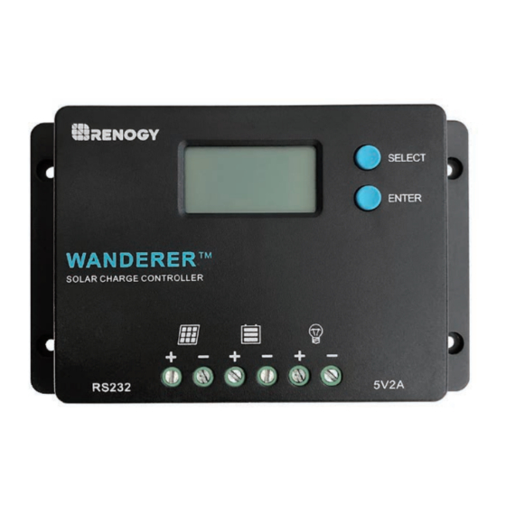
Product Overview Identification of Parts ① ③ ② ⑧ ⑦ ⑥ ⑤ ④ Key Parts LCD Screen ① Select Button ② Enter Button ③ USB Ports ④ Load Terminals ⑤ Battery Terminals ⑥ PV Terminals ⑦ RS232 Communication Port ⑧... -
Page 7: Dimensions
NOTE Optional Components Renogy BT-1 Bluetooth Module (Model: RCM-BT1) The RCM-BT1 is a great addition to Renogy charge controllers with an RS232 port. Pair the controller using the BT-1 Module and the Renogy DC Home App to monitor your system using a smart phone or tablet. -
Page 8: Installation
Installation WARNING Connect the battery to the charge controller BEFORE connecting the solar panel(s) unless you have the solar suitcase with controller exception. The controller needs a stable power source to operate. CAUTION Do not over-torque or over tighten the screw terminals. This could potentially break the piece that holds the wire to the charge controller. -
Page 9: Wiring And Fusing
Wiring and Fusing The wire terminals are closed by default. NOTE Use bare wiring when connecting to the Wanderer’s terminal blocks. Due to default positioning, you must ensure that the terminal hatch is completely open before the first-time use. 1.Make sure to rotate the hatch counterclockwise (CCW) into the open position to expose the wire hatch 2.Insert bare wire into the terminal for the respective connection... - Page 10 Open Terminal Block Closed Terminal Block Depending on the PV Array wiring and battery size, the recommended fuse and cable gauge will depend on the actual amps flowing through the cable. The following chart accounts for less than 3% voltage drop and may not account for all configura- tions.
- Page 11 Current Fuse from Controller to Battery Controller to Battery Fuse = Current Rating of Charge Controller Ex. Wanderer 10 = 10A fuse from Controller to Battery Fuse from Solar Panel(s) to Controller Ex. 200W; 2 X 100 W panels Parallel Total Amperage = Isc1 + Isc2 = (5.75A + 5.75A) * 1.2...
- Page 12 Battery Wiring WARNING Connect the battery to the charge controller BEFORE connecting the solar panel(s) unless you have the solar suitcase with controller exception. The controller needs a stable power source to operate. counterclockwise clockwise counterclockwise clockwise...
- Page 13 PV Wiring counterclockwise clockwise counterclockwise clockwise...
- Page 14 Load Wiring (Optional) counterclockwise clockwise counterclockwise clockwise Communication Wiring (Optional)
-
Page 15: Operation
ENTER Long Press—Hold to enter Setting Mode Auto Recognition The Wanderer controller will be able to automatically detect the battery voltage for Non-Lithium 12V or 24V batteries. Lithium batteries need to be manually programzmed and can be found in Settings. -
Page 16: Lcd Overview
LCD Overview Parameter Value Port Battery type Amps/Volts System Voltage Solar Panel Battery Load Icon or Value State Description Solar Panels Charging Steady on Battery Battery Voltage (16.1V+) 3 Bars Flashing Battery Voltage 3 Bars (12.9V- 16.0V) Battery Voltage (12.5-12.8V) 2 Bars 1 Bar Battery Voltage (11.6-12.4V) -
Page 17: Mppt Technology
Four Charging Stages The Wanderer has a 4-stage battery charging algorithm for a rapid, efficient, and safe battery charging. They include: Bulk Charge, Boost Charge, Float Charge, and Equalization. - Page 18 Bulk Charge: This algorithm is used for day to day charging. It uses 100% of available solar power to recharge the battery and is equivalent to constant current. Boost Charge: When the battery has charged to the Boost voltage set-point, it undergoes an absorption stage which is equivalent to constant voltage regulation to prevent heating and excessive gassing in the battery.
-
Page 19: Settings
Without the wake-up feature to activate and charge batteries, these batteries would become unserviceable and the packs would be discarded. The Wanderer will apply a small charge current to activate the protection circuit and if a correct cell voltage can be reached, it starts a normal charge. - Page 20 Battery Type Lithium Press SELECT until you highlight the Battery Voltage Screen where it should demonstrate the battery icon and voltage. 1.Highlight Battery Voltage Screen 2.Hold ENTER for approximately 3s until the battery type starts to flash 3.Tap SELECT to highlight Lithium battery, Tap ENTER to confirm Lithium 4.Tap SELECT to highlight nominal battery voltage as 12V or 24V, Tap Enter to confirm...
-
Page 21: Load Terminal
Battery Type System Voltage Load Terminal Make sure the load is compatible with the battery type WARNING of the system. 12V loads damaged in 24V battery systems will not be covered in warranty. The Load Terminal allows you to connect DC devices directly to the controller with timer functions as optional features. - Page 22 Press SELECT until you highlight the Load Mode Screen where it should demonstrate a numerical load mode. The following chart indicates numbers representing hours ON that the load terminal Mode Description Setting The load will turn on at night when the solar panel is no longer producing Automatic any power after a short time delay.
-
Page 23: Troubleshooting
If the battery voltage is low it may be in open battery protection mode, which is a Wanderer Protection. Use a multi-meter to get a reading of the battery voltage in volts DC to validate Battery error code. - Page 24 Error Meaning Troubleshoot Code Load has exceeded 10Amps DC. Connect simple electronics to the load terminal and do not connect devices such as inverters, Load battery chargers, or other high amp Overloaded devices. Disconnect your load, double check the rating, and double check the correct Load Mode is on.
-
Page 25: Maintenance
DC. If the number is negative, switch the positive and negative battery cables in the battery terminal of the Wanderer. Maintenance WARNING Risk of Electric Shock! Make sure that all power is turned off before touching the terminals on the charge controller. -
Page 26: Technical Specifications
Technical Specifications Parameter Description Nominal Voltage 12V/24V Auto Recognition Rated Charge Current Max. PV Input Voltage 55 VDC USB Output 5V, 2A max Self-consumption ≤10mA Operating Temperature -25℃ to +45℃ | -31℉ to 113℉ Storage Temperature -35℃ to +80℃ | -31℉ to 176℉ Enclosure IP20 Terminals... - Page 27 Battery Charging Parameters All the coefficient is referred to 25℃ Battery SLD/AGM FLOODED LI (LFP) High Voltage 16 V 16 V 16 V 16 V Disconnect Over-voltage 15 V 15 V 15 V 15 V Reconnect Equalization ----- ----- ----- 14.6 V Voltage 14.2 V...
- Page 28 RENOGY.COM Renogy reserves the right to change the contents of this manual without notice. 2775 E Philadelphia St, Ontario, CA 91761, USA 909-287-7111 www.renogy.com support@renogy.com 苏州高新区科技城培源路1号5号楼-4 400-6636-695 https://www.renogy.cn support@renogy.cn https://www.renogy.jp supportjp@renogy.com https://ca.renogy.com supportca@renogy.com https://au.renogy.com supportau@renogy.com https://uk.renogy.com supportuk@renogy.com https://de.renogy.com supportde@renogy.com...
Need help?
Do you have a question about the WANDERER and is the answer not in the manual?
Questions and answers