
Related Manuals for Renogy RNG-CTRL-MPPT20


Summary of Contents for Renogy RNG-CTRL-MPPT20
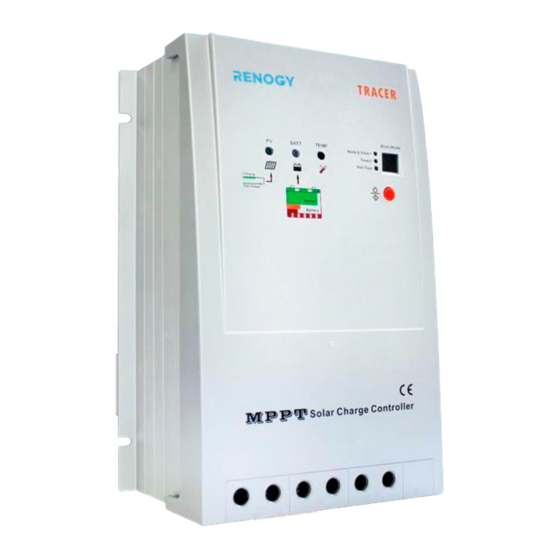
- Page 1 MPPT Tracer Series RENOGY 20A | 40A Maximum Power Point Tracking Solar Charge Controller 2775 E. Philadelphia St., Ontario, CA 91761 1-800-330-8678 Version: 1.1...
- Page 2 Important Safety Instructions Please save these instructions. This manual contains important safety, installation, and operating instructions for the charge controller. The following symbols are used throughout the manual to indicate potentially dangerous conditions or important safety information. WARNING: Indicates a potentially dangerous condition. Use extreme caution when performing this task.
- Page 3 Explosive battery gases may be present while charging. Be certain there is enough ventilation to release the gases. Be careful when working with large lead acid batteries. Wear eye protection and have fresh water available in case there is contact with the battery acid. ...
-
Page 4: Table Of Contents
Table of Contents General Information ...................... 5 Optional Components ....................8 Identification of Parts ....................9 Installation ........................10 Operation ........................13 Load Work Mode Setting ..................14 Battery Type Setting ....................17 LED Indications ......................18 System Status Troubleshooting ................19 Maintenance ........................ -
Page 5: General Information
General Information The RENOGY MPPT series controller is suitable for off-grid solar applications. It protects the battery from being over-charged by the solar modules and over-discharged by the loads. The controller features a smart tracking algorithm that maximizes the energy from the solar PV module(s) and charge the battery. - Page 6 The current does not come out of thin air. Instead, the power generated in the solar panels is the same power that is transmitted into the battery bank. Power is the product of Voltage (V) x Amperage (A). Therefore, assuming 100% efficiency: Power In = Power Out Volts In * Amps In = Volts out * Amps out Although MPPT controllers are not 100% efficient, they are very close at about 92-95%...
- Page 7 Four Charging Stages The MPPT charge controllers have a 4-stage battery charging algorithm for a rapid, efficient, and safe battery charging. They include: Bulk Charge, Boost Charge, Float Charge, and Equalization. Bulk Charge: This algorithm is used for day to day charging. It uses 100% of available solar power to recharge the battery and is equivalent to constant current.
-
Page 8: Optional Components
*The MPPT 20A/40ACC is shipped by itself, without any additional components. Optional components that require a separate purchase: Renogy MT-5 Tracer Meter for MPPT Charge Controller (MT-5): A self-diagnostics meter ideal for monitoring and displaying the current solar system status information and Figure 1 any error indications the system might be experiencing. -
Page 9: Identification Of Parts
Identification of Parts 30A/40A MPPT 20A MPPT BATTERY LOAD Terminal Terminal Terminal Key Parts 1. Charging LED Indicator 2. Battery Status LED indicator 3. Local Temperature Sensor—acquires ambient temperature to perform temperature compensation for charging and discharging. 4. Setting LED Indicators—Work Mode, Timers, and Battery Selection 5. -
Page 10: Installation
Installation Recommended tools to have before installation: Flathead Screwdriver Multi-Meter WARNING: Connect battery terminal wires to the charge controller FIRST then connect the solar panel(s) to the charge controller. NEVER connect solar panel to charge controller before the battery. WARNING: connect any inverters or battery chargers into the load terminal of the charge controller INVERTER... - Page 11 Battery Load (optional)
- Page 12 Solar Panels MT-5 Tracer (optional)
-
Page 13: Operation
Mounting Recommendations WARNING: Never install the controller in a sealed enclosure with flooded batteries. Gas can accumulate and there is a risk of explosion. 1. Choose Mounting Location—place the controller on a vertical surface protected from direct sunlight, high temperatures, and water. Make sure there is good ventilation. -
Page 14: Load Work Mode Setting
NOTE: In order to adjust a parameter go to your desired LED indicator, hold the orange set button for a little over 5 seconds. Wait until the number inside the Work Mode display flashes. You are now in parameter setting mode and can continually press the orange set button and cycle through the numbers until the desired number is reached. - Page 15 The MPPT Charge Controller is equipped with a programmable dual timer function for the load terminal. Depending on the user setting, the timer(s)’ purpose is to turn on/off the load for a selected amount of time during the day, during the night, or manually to the user’s discretion.
- Page 16 voltage goes above point of DTTV (Day Time Threshold Voltage). The controller will recognize the voltage increase and undergo a 10 minute delay before turning off the load terminal. If Timer 1 has already been set to a time frame before night time is over, then Timer 2 will be able control the amount of hours the load turns on again before reaching the DTTV.
-
Page 17: Battery Type Setting
Timing Parameters Timer 1 Digital Display Timer 2 Disable Disable Dusk To Dawn ----- Load on 1 hour AFTER sunset Load on 1 hour BEFORE sunrise Load on 2 hour AFTER sunset Load on 2 hour BEFORE sunrise Load on 3 hour AFTER sunset Load on 3 hour BEFORE sunrise Load on 4 hour AFTER sunset Load on 4 hour BEFORE sunrise... -
Page 18: Led Indications
LED Indications Charge Indicator Solid. Battery is charging No light. Not charging. Flashing. Battery is over-voltage. Battery Indicator Solid. Battery Normal. Flashing. Battery is Full. Solid. Battery is under-voltage. Solid. Battery is over-discharged. Flashing. The load is either over-current or short- circuited. -
Page 19: System Status Troubleshooting
System Status Troubleshooting Charge Indicator Troubleshoot Ensure that the PV wires are correctly and tightly secured inside Off during the charge controller PV terminals. Use a multi-meter to make sure daylight the poles are correctly connected to the charge controller. Use a multi-meter to check the battery voltage and make sure it is Flashing Green within specification for the charge controller. -
Page 20: Maintenance
Work Mode Troubleshoot The controller is registering an overcurrent from the solar modules. Check solar panel specifications and verify with a multi-meter to The letter “C” see that they match. Next check to see if the panel specifications and I ) are within specification for the charge controller. -
Page 21: Fusing
Fusing Fusing is a recommended in PV systems to provide a safety measure for connections going from panel to controller and controller to battery. Remember to always use the recommended wire gauge size based on the PV system and the controller. NEC Maximum Current for different Copper Wire Sizes Max. -
Page 22: Technical Specifications
Technical Specifications Electrical Parameters Model Tracer-2210RN Tracer-4210RN Nominal system 12V/24V Auto Recognition voltage Rated Battery Current Rated Load Current Max. Battery Voltage Max Solar Input 100 VDC @ Minimum Working Temperature Voltage 92 VDC @ 25°C Max. Solar Input Power 12V @ 200W 12V @ 400W 24V @ 400W... -
Page 23: Mechanical Parameters
Discharging Limit 10.8 V 10.8 V 10.8 V Voltage Equalization Duration ----- 2 hours 2 hours Boost Duration 2 hours 2 hours 2 hours **Parameters are multiplied by 2 for 24V systems. Mechanical Parameters Model Tracer-2210RN Tracer-4210RN Overall Dimension 169 x 118 x 83mm 240 x 169 x 91mm 6.65 x 4.65 x 3.28in. -
Page 24: Pv Power - Conversion Efficiency Curves-20A Mppt
PV Power – Conversion Efficiency Curves—20A MPPT... -
Page 27: Pv Power - Conversion Efficiency Curves-40A Mppt
PV Power – Conversion Efficiency Curves—40A MPPT... -
Page 30: Dimensions
Dimensions 20A 2210RN NOTE: All dimensions are in inches... - Page 31 40A 4210RN NOTE: All dimensions are in inches Renogy reserves the right to change the contents of this manual without notice. Revision: 4/5/2016...
Need help?
Do you have a question about the RNG-CTRL-MPPT20 and is the answer not in the manual?
Questions and answers