
Related Manuals for Renogy MPPT Series


Summary of Contents for Renogy MPPT Series
- Page 1 MPPT40CC RENOGY 40A Maximum Power Point Tracking Solar Charge Controller Manual 14288 Central Ave., Suite A Chino, CA 91710 1-800-330-8678...
-
Page 2: Table Of Contents
Contents 1. Important Safety Information 2. General Information 2.1 Overview 2.2 Optional Accessories 3. Installation Instructions 3.1 General Installation Notes 3.2 Mounting 3.3 Wiring 4. Operation 4.1 MPPT Technology 4.2 Battery Charging Information 4.3 LED Indications 4.4 Setting Operation 5. Protections, Troubleshooting and Maintenance 5.1 Protection 5.2 Troubleshooting 5.3 Maintenance... -
Page 3: Important Safety Information
1. Important Safety Information Save These Instructions This manual contains important safety, installation and operating instructions for the MPPT40CC controller. The following symbols are used throughout this manual to indicate potentially dangerous conditions or mark important safety instructions. Please take care when meeting these symbols. WARNING: Indicates a potentially dangerous condition. -
Page 4: General Information
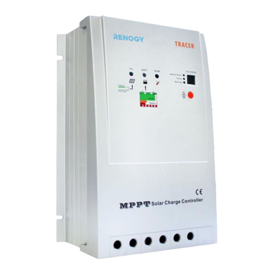
2. General Information 2.1 Overview The RENOGY MPPT series controller is suitable for off-grid solar applications. It protects the battery from being over-charged by the solar modules and over- discharged by the loads. The controller features a smart tracking algorithm that maximizes the energy from the solar PV module(s) and charge the battery. - Page 5 Description of MPPT40CC controller: Figure 2-1 MPPT40CC Characteristics 1. Charging Status LED indicator 2. Battery Status LED indicator 3. Temperature Sensor 4. Setting Indicators 5. LED Digital Display the load work mode and status. 6. Setting Button (in manual mode used for load ON/OFF) 7.
-
Page 6: Optional Accessories
2.2 Optional Accessories Remote Meter (Model: MT-5) The digital remote meter displays system operating information, error indications, and self-diagnostics read-out. Information is displayed on a backlit LCD display. The large numerical display and icons are easy to read and large buttons make navigating the meter menus easy. -
Page 7: Installation Instructions
3. Installation Instructions 3.1 General Installation Notes • Read through the entire installation section first before beginning installation. • Be very careful when working with batteries. Wear eye protection. Have fresh water available to wash and clean any contact with battery acid. •... -
Page 8: Wiring
Step 1: Choose mounting location Locate the MPPT40CC on a vertical surface protected from direct sunlight, high temperature, and water. Step 2: Check for Clearance Place the MPPT40CC in the location where it will be mounted. Verify that there is sufficient room to run wires and that there is sufficient room above and below the controller for airflow. - Page 9 Step 1: Battery Wiring WARNING: Risk of explosion or fire! Never short circuit battery positive (+) and negative (-) or cables Figure 3-1 Battery wiring Before connecting the battery, measure the battery voltage. It must be over 9V to power the controller. For 24V, the voltage must be greater than 18V to properly detect a 24V battery.
- Page 10 shown. Do not insert a fuse at this time. Confirm the connection is correct and then turn on the power. If wiring the load connection to a load distribution panel, each load circuit should be fused separately. The total load draw should not exceed the 20A load rating. Step 3: Solar Module Wiring WARNING: Risk of electric shock! Exercise caution when handling solar wiring.
-
Page 11: Operation
4. Operation 4.1 MPPT Technology The MPPT40CC utilizes Maximum Power Point Tracking technology to extract maximum power from the solar module(s). The tracking algorithm is fully automatic and does not require user adjustment. MPPT technology will track the array’s maximum power point voltage (Vmp) as it varies with weather conditions, ensuring that the maximum power is harvested from the array throughout the course of the day. - Page 12 Output Power (12V System) Current vs. Voltage (12V System) Typical Battery Maximum Maximum Voltage Range Power Point Power Point Traditional Controller Operating Range Figure 4-1 Nominal 12V Solar Module I-V curve and output power graph The array Vmp is the voltage where the product of current and voltage (Amps × Volts) is greatest, which falls on the knee of the solar module I-V curve as shown in Figure 4-1.
-
Page 13: Battery Charging Information
4.2 Battery Charging Information Four Charging Stages The MPPT40CC has a 4-stage battery-charging algorithm for rapid, efficient, and safe battery charging. Figure 4-2 MPPT40CC MPPT charging algorithm Bulk Charge In this stage, the battery voltage has not yet reached boost voltage and 100% of available solar power is used to recharge the battery. -
Page 14: Led Indications
Equalize WARNING: Risk of explosion! Equalizing flooded batteries can produce explosive gases, so a well-ventilated battery box is necessary. NOTE: Equipment damage! Equalization may increase battery voltage to a level damaging to sensitive DC loads. Ensure that all load allowable input voltages are greater than the equalizing charging set point voltage. - Page 15 Charging Indicator The green LED indicator will turn on whenever sunlight is available for battery charging. Under normal charging conditions, the green charging LED will stay on at all times. The charging LED indicator flashes when the battery reaches over- voltage.
-
Page 16: Setting Operation
Load indicator When the load amperage is 1.25 times of rated current for 60 seconds, 1.5 times of rated current for 5 seconds (overload), or there is a load short circuit, the Battery LED indicator will be flashing RED. Please refer to section 5 for troubleshooting. - Page 17 on the load after 10 minutes delay for several hours which users set on the timer. The timer setting operation is referred to as “Load Work Mode Setting”. 3. Test Mode It is used to test the system and the same as Dusk to Dawn. But there is no 10- minute delay when controller recognizes the starting voltage.
- Page 18 Timer 1 LED Digital No. Disable Dusk-to-Dawn, Load will be on all night Load will be on for 1 hour after a ten minute delay since sunset Load will be on for 2 hours after a ten minute delay since sunset Load will be on for 3 hours after a ten minute delay since sunset Load will be on for 4 hours after a ten minute delay since sunset Load will be on for 5 hours after a ten minute delay since sunset...
- Page 19 Battery Type Setting When the Battery setting indicator is on, press the “Setting” button and hold on 5 seconds until the battery type LED turns on. The led will be flashing. Continue to hold and the number will repeat from 1 to 3, and stop pressing until the desired number appears according to the following setting table: Battery type Digital display...
-
Page 20: Protections, Troubleshooting And Maintenance
5. Protections, Troubleshooting and Maintenance 5.1 Protection PV Array Short Circuit If PV array short circuit occurs, clear it to resume normal operation. PV Overvoltage If PV Overvoltage occurs, the array will remain disconnected until the voltage falls safely below the maximum rating. PV Overcurrent If PV Overcurrent occurs, the array will be disconnected automatically. -
Page 21: Troubleshooting
High Voltage Transients PV is protected against high voltage transients. In lightning prone areas, additional external suppression is recommended. 5.2 Troubleshooting Faults Possible reasons Troubleshooting Charging LED indicator off during PV array disconnection Check that PV and battery wire daytime when panels are in direct connections are correct and tight. -
Page 22: Maintenance
5.3 Maintenance The following inspections and maintenance tasks are recommended at least two times per year for best controller performance: • Check that the controller is securely mounted in a clean and dry environment. • Check that the airflow and ventilation around the controller is not blocked. Clear all dirt or fragments on the heat sink. -
Page 23: Warranty
6. Warranty The MPPT40CC charge controller is warranted to be free from defects for a period of ONE (1) year from the date of shipment to the original end user. We will, at our option, repair or replace any such defective products. Claim procedure: Before requesting warranty service, check the Operation Manual to be certain that there is a problem with the controller. -
Page 24: Technical Specifications
7. Technical Specifications Electrical Parameters Description Parameter Nominal System Voltage 12VDC/24VDC Auto recognition Rated Charge Current Rated Discharge Current Maximum Battery Voltage Max. Solar Input Voltage* 100VDC Max. PV Input Power 500W (12V), 1000W (24V) Self-consumption** <10mA (24V) Charge Circuit Voltage Drop ≤... - Page 25 Threshold Voltage Description Parameter NTTV (Night Time Threshold Voltage) 5V; x2/24V DTTV (Day Time Threshold Voltage) 6V; x2/24V Table 7-3 Threshold Voltages Temperature Compensation Description Parameter Temperature Compensation Coefficient -30mV/°C/12V (25°C ref) (TEMPCO)* Table 7-4 Temperature Compensation *Compensation of equalize, boost, float and low voltage disconnect voltage Environmental Parameters Environmental Parameter...
- Page 26 PV Power – Conversion Efficiency Curve Illumination Intensity: 1000W/m Temperature: 25°C 1. Solar Module MPP Voltage (17V) / Nominal System Voltage (12V) 2. Solar Module MPP Voltage (34V) / Nominal System Voltage (12V) ...
- Page 27 3. Solar Module MPP Voltage (68V) / Nominal System Voltage (12V) 4. Solar Module MPP Voltage (34V) / Nominal System Voltage (24V) ...
- Page 28 5. Solar Module MPP Voltage (68V) / Nominal System Voltage (24V) ...
- Page 29 MPPT40CC Dimensions (mm) ...
Need help?
Do you have a question about the MPPT Series and is the answer not in the manual?
Questions and answers