Advertisement
Quick Links
*030690-000-70*
030690-000-70
* NOTE: UL LATCH SHIELD IS ONLY
REQUIRED WITH UL LATCHES
1. MARK DOOR
A. Mark height line on edge of door
approximately 38" from floor.
B. Using the proper backset, mark 2¹⁄₈" hole on
both sides of the door.
C. On the outside of door, mark notches.
D. Mark the center of the door edge for the latch.
4. INSTALL LATCH SHIELD
FOR UL LATCH OPTION ONLY
A. Insert latch shield
(closed end first)
from the outside of the door.
5. INSTALL LATCH
A. Insert latch into door, making certain that
bevel faces direction of closing door.
B. Secure with two #8 combo screws provided.
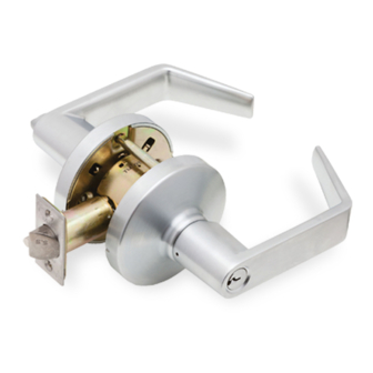
F-Series
Keyed Locks
UL
LATCH
OUTSIDE
SHIELD *
LEVER
ASSY
2. DOOR PREPARATION
A. Bore 2¹⁄₈"
hole thru from
both sides of
door to prevent
splintering door
finish.
B. File notches on
outside of door being careful not
to exceed the 2¹⁵⁄₃₂" dimension.
C. Bore 1" hole for latch on door
edge.
D. Using the latch faceplate as a
guide, trace outline and mortise
door edge so latch is flush with
door.
NOTE: Hollow metal doors must be properly
reinforced for lock support. If support was not
furnished contact door manufacturer.
6. INSTALL OUTER TRIM
A. Align spindle with latch unit
and insert outer trim into door.
CAUTION:
Failure to
use the latch
shield with a
UL latch will
invalidate the
UL listing of
this product.
Customer Service
1-877-671-7011
ROSE
INSIDE
SPINDLE
ASSY
LATCH ASSY
3. INSTALL STRIKE
NOTCHES
A. Use strike locating tool or pointed
object to locate position for hole in frame.
B. Bore 1" x ³⁄₄" deep hole. Use strike as a
template and mortise to the proper depth.
1"
HOLE
2¹⁄₈"
HOLE
7. INSTALL INNER SPINDLE
ASSEMBLY
A. Align spindle assembly with square
shaft and slide into place.
NOTE: Locking button must be positioned
towards the edge of the door.
B. Secure with two screws provided.
www.allegion.com/us
Installation Instructions
INSIDE
LEVER
#10-32
MACHINE
SCREWS
#8 COMBO
SCREWS
C. If dust box is to
be used, clear area
with wood chisel.
locking button
© Allegion 2014
Printed in U.S.A.
030690-000-70 Rev. 10/14-d
Advertisement

Subscribe to Our Youtube Channel
Related Manuals for Allegion Falcon F Series


Summary of Contents for Allegion Falcon F Series
- Page 1 5. INSTALL LATCH A. Insert latch into door, making certain that locking button bevel faces direction of closing door. B. Secure with two #8 combo screws provided. © Allegion 2014 Customer Service Printed in U.S.A. 030690-000-70 Rev. 10/14-d 1-877-671-7011 www.allegion.com/us...
- Page 2 TEMPLATE FALCON F-SERIES LOCKS FIRST: IMPORTANT: BORE 2¹⁄₈” (54mm) HOLE AT CORRECT BACKSET NOTCHES REQUIRED SECOND: IN EXTERIOR SIDE OF BORE LATCH HOLE DOOR FOR LOCK TO PARALLEL TO MOUNT & FUNCTION PROPERLY. SIDES 1” (25mm) DISTANCE FROM EDGE OF DOOR 2³⁄₄”...
- Page 3 Revision 3. tolerance ± .13 10-22-14 4. printed in country may vary 030690-000-70 5. drawings not to scale Created By 6. Barcode shows after folding Activity J. Ellis 3899 Hancock Expwy Security, CO 80911 Software: InDesign CS6 © Allegion 2014...
Need help?
Do you have a question about the Falcon F Series and is the answer not in the manual?
Questions and answers