Table of Contents
Advertisement
Quick Links
Advertisement
Table of Contents

Subscribe to Our Youtube Channel
Related Manuals for Allegion interflex IF-261


Summary of Contents for Allegion interflex IF-261
- Page 1 Opendor IF-261 Cabinet Lock OF-261-0xxxx...
-
Page 2: Table Of Contents
Table of contents General information......................Short description....................... Range of functions....................Scope of delivery ...................... Target group ......................Intended use ......................Safety........................Installation and configuration..................... Dimensions ....................... Installation situation ....................Measurement and calculation................... Installation......................... 10 Configuration ......................23 Operation ..........................24 Opening a door ...................... -
Page 3: General Information
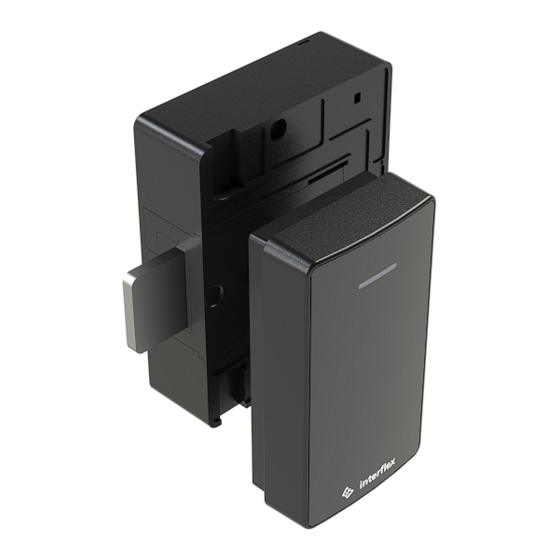
1 General information 1 General information 1.1 Short description The electronic IF-261 Cabinet Lock from the Opendor line of products provides the highest level of security for storage cabinets and lockers. The Cabinet Lock is the ideal solution for cost-effective, uncomplicated and wireless compliance with current security standards for a wide range of applications. -
Page 4: Target Group
1 General information Check the completeness and condition of the goods upon receipt and report any damage caused during transport immediately. 1.4 Target group This document is solely intended for experts and people trained in electrical engineering. Only perform the actions described in this document if you belong to this target group. Interflex Datensysteme GmbH is not liable for any damages caused by improper installation or initial operation. - Page 5 1 General information Batteries CAUTION Risk of explosion due to incorrect battery type Inserting the wrong type of battery can cause an explosion. Only use the batteries specified in the technical specifications. NOTICE Batteries can be a fire hazard Batteries may pose a fire or burn hazard if handled incorrectly. Do not attempt to charge, open, heat or incinerate the batteries.
-
Page 6: Installation And Configuration
2 Installation and configuration 2 Installation and configuration 2.1 Dimensions Dimensions of the reader unit © 2022 Interflex Datensysteme GmbH | IF-261 Cabinet Lock | 06.22... - Page 7 2 Installation and configuration Dimensions of the lock © 2022 Interflex Datensysteme GmbH | IF-261 Cabinet Lock | 06.22...
-
Page 8: Installation Situation
2 Installation and configuration 2.2 Installation situation Observe the minimum and maximum distances allowed when installing the Cabinet Lock: Door frames Angle brackets Door Spacer plates Variable spacer plate Installation of Cabinet Lock on wooden door Door frames Angle brackets Door Spacer plates Variable spacer plate... -
Page 9: Measurement And Calculation
2 Installation and configuration Door frames Angle brackets Door Spacer plates Variable spacer plate Installation of Cabinet Lock on metal door 2 2.3 Measurement and calculation To install the cabinet lock, you will need different spacer plates, locking blocks, flange extensions and screws, depending on local conditions. -
Page 10: Installation
2 Installation and configuration Inside of the door up to the bolt stop [mm] Spacer plate [mm] Locking block 18.95 to 20.45 2 × 5 20.55 to 20.95 3 × 5 21.05 to 22.25 3 × 5 22.35 to 23.85 3 ×... - Page 11 2 Installation and configuration Additionally required tools Phillips screw driver PH1 Flat-bladed screwdriver (if locking block has to be replaced) Hexagon key 2.5 mm Prerequisites ü Cabinet lock closed, bolt extended ü Door and parts measured [} 9] Procedure 1. Press the cover of the reader unit lightly against the bottom and turn the lower screw clockwise inwards until you are able to lift the cover off 2.
- Page 12 2 Installation and configuration 5. Insert the socket into the D-hole (fixture for the nut points to the edge of the door) 6. Plug the variable spacer plate (with the parallel forced guide) onto the socket from the back © 2022 Interflex Datensysteme GmbH | IF-261 Cabinet Lock | 06.22...
- Page 13 2 Installation and configuration 7. Slide out the positive guide until it touches the inside edge of the door 8. Press the positive guide further against the inside edge and tighten the screws until the positive guide can no longer be moved ©...
- Page 14 2 Installation and configuration 9. If necessary, attach additional spacer plates 10. If the locking block has to be replaced: Lever the locking block out of the lock and insert another one into the lock © 2022 Interflex Datensysteme GmbH | IF-261 Cabinet Lock | 06.22...
- Page 15 2 Installation and configuration 11. Insert the screw into the fixture and hold it in place 12. Fix the screw through the bolt-side hole on the back © 2022 Interflex Datensysteme GmbH | IF-261 Cabinet Lock | 06.22...
- Page 16 2 Installation and configuration 13. If necessary, attach the flange extensions to the lock 14. Optional for wooden doors: Insert the lugs © 2022 Interflex Datensysteme GmbH | IF-261 Cabinet Lock | 06.22...
- Page 17 2 Installation and configuration 15. Hold the installation tool with one finger and place the lock on the spacer plate or through the D-hole socket 16. Optional for wooden doors: Fasten the lugs © 2022 Interflex Datensysteme GmbH | IF-261 Cabinet Lock | 06.22...
- Page 18 2 Installation and configuration 17. Run the connector cable through the socket 18. Place the nut on the bolt and carefully tighten it with the already attached installation tool until it sits in the hexagonal fixture 19. Tighten the nut ©...
- Page 19 2 Installation and configuration 20. Insert the tensioning element and plastic countersunk screw into the D-hole socket from the front 21. Tighten the tensioning element as far as it goes without turning the screw 22. Place the reader unit on the bayonet mount at an angle of approx. 45° ©...
- Page 20 2 Installation and configuration 23. Align reader unit by turning clockwise until straight 24. Connect mounting tool and connector 25. Insert the plug into the socket with the catch facing up 26. Guide the cable past the reader unit to the side ©...
- Page 21 2 Installation and configuration 27. Attach the light conductor and press firmly in order to protect the reader unit from twisting 28. Route the cable neatly on the side 29. Insert the cover into the catch on top © 2022 Interflex Datensysteme GmbH | IF-261 Cabinet Lock | 06.22...
- Page 22 2 Installation and configuration 30. Push the cover downwards to close it 31. Press the cover lightly against the bottom and turn the lower screw counterclockwise until it is flush with the surface of the cover © 2022 Interflex Datensysteme GmbH | IF-261 Cabinet Lock | 06.22...
-
Page 23: Configuration
2 Installation and configuration 2.5 Configuration The configuration and the management of the components are described in a separate documentation: card Opendor components Configuration with card set: Interflex Offline components Configuration with the software DoorManager: in the corresponding technical manual Opendor components Technical manual for IF-4041 Gateway... -
Page 24: Operation
3 Operation 3 Operation The following sections describe the operation of the IF-261 Cabinet Lock. The technical basics can be found in the separate document Interflex Offline Components Hold the credential in front of the lock. If the credential is authorized, the LED will flash green briefly and the lock is opened. Depending on the configuration, the Cabinet Lock is automatically locked after the closing time has elapsed or it remains unlocked until a new booking is made. -
Page 25: Maintenance, Cleaning, And Disinfection
4 Maintenance, cleaning, and disinfection Activating the permanently open mode Hold the credential up to the reader unit for more than three seconds IF-261 Cabinet Lock indicates the Permanently open On log file entry: 3 x green Standard + Permanently open Green Permanently open Deactivating the permanently open mode... - Page 26 4 Maintenance, cleaning, and disinfection Procedure 1. Insert the screwdriver into the provided opening 2. Lift the cover by twisting the screwdriver and push towards the edge of the housing 3. Replace battery 4. First insert the long and then the short tab of the battery compartment’s cover 5.
-
Page 27: Reset (Cold Boot)
4 Maintenance, cleaning, and disinfection If you ignore the battery warnings, there is a chance that the Cabinet Lock may fail. In such case, the battery compartment is no longer accessible. To replace the batteries, you can connect it to an emergency power supply. Emergency power supply The Cabinet Lock possesses a micro USB port for emergency power supply using standard power banks. -
Page 28: Technical Specifications
5 Technical specifications 5 Technical specifications Power supply Battery 2 lithium batteries, type AA 1.5 V Battery life Approx. 80,000 actuations depending on the technology used at 20 °C, standby time up to 12 years Equipment Modes of operation Online wireless, offline NoC Interfaces BLE 5 to gateway Micro USB for emergency power supply... -
Page 29: Disposal
The original manual is in German. Other languages are translations of the original manual. Version: 06.22 Interflex Datensysteme GmbH +49 711 1322 - 0 Epplestraße 225 (Haus 3) interflex.info@allegion.com 70567 Stuttgart, Germany www.interflex.com © 2022 Interflex Datensysteme GmbH | All specifications are subject to change without notice.
Need help?
Do you have a question about the interflex IF-261 and is the answer not in the manual?
Questions and answers