Table of Contents
Advertisement
Quick Links
*P516-085*
P516-085
1
Important Information
• Lock comes preset with a default Programming Code.
• Lock comes preset with two default User Codes
Default Programming Code
Código de programación predeterminado
Code du défaut programmation
Place Label Here
Default User Codes
Poner la etiqueta aquí
Códigos de usuario predeterminado
Placer l'autocollant ici
Codes du défaut utilisateur
2
2a. Check dimensions.
If door dimensions do not match, go to
www.nexiahome.com for drilling instructions.
2C\," (60 mm)
OR
2C\v" (70 mm)
5Z\x"
(140 mm)
2³⁄₈" (60 mm)
2³⁄₈" (60 mm)
2Z\," (53 mm)
Hole
3
3a. Check the cam on the interior baseplate.
Locate the cam on the baseplate. This cam has a small arrow on it that
should point to the arrow that is printed on the casing above the cam, like
picture "a" below. If the cam is oriented sideways, like the picture "b",
rotate the cam until the arrows match.
a
b
4
Correct
Match arrows
Match arrows
!
!
Las flechas deben quedar alineadas
Las flechas deben quedar alineadas
Aligner les flèches
Aligner les flèches
4
4a. Secure interior baseplate.
Use the two screws shown to secure the baseplate to the door.
5
5a. Install cover.
Place the cover against the door and secure using the two screws. You may
need to rotate the thumbturn to the proper position, shown below.
Tuck wires into open space on baseplate. Be careful not to pinch any wires
between cover and baseplate.
Thumbturn
ck
Para cerrar
Pour verrouiller
ess
otate turn towards door edge
esione
re hacia el borde externo de la puerta
esser
7
urner vers le bord de la porte
Test lock.
TEST WITH DOOR OPEN!
7a. Test locking function.
To Lock
Para cerrar
Pour verrouiller
1. Press
a. Press
2. Rotate thumbturn towards door edge until bolt extends.
b. Rotate turn towards door edge
a. Presione
b. Gire hacia el borde externo de la puerta
a. Presser
b. tourner vers le bord de la porte
Yes. Lock is installed correctly.
uiller
ta
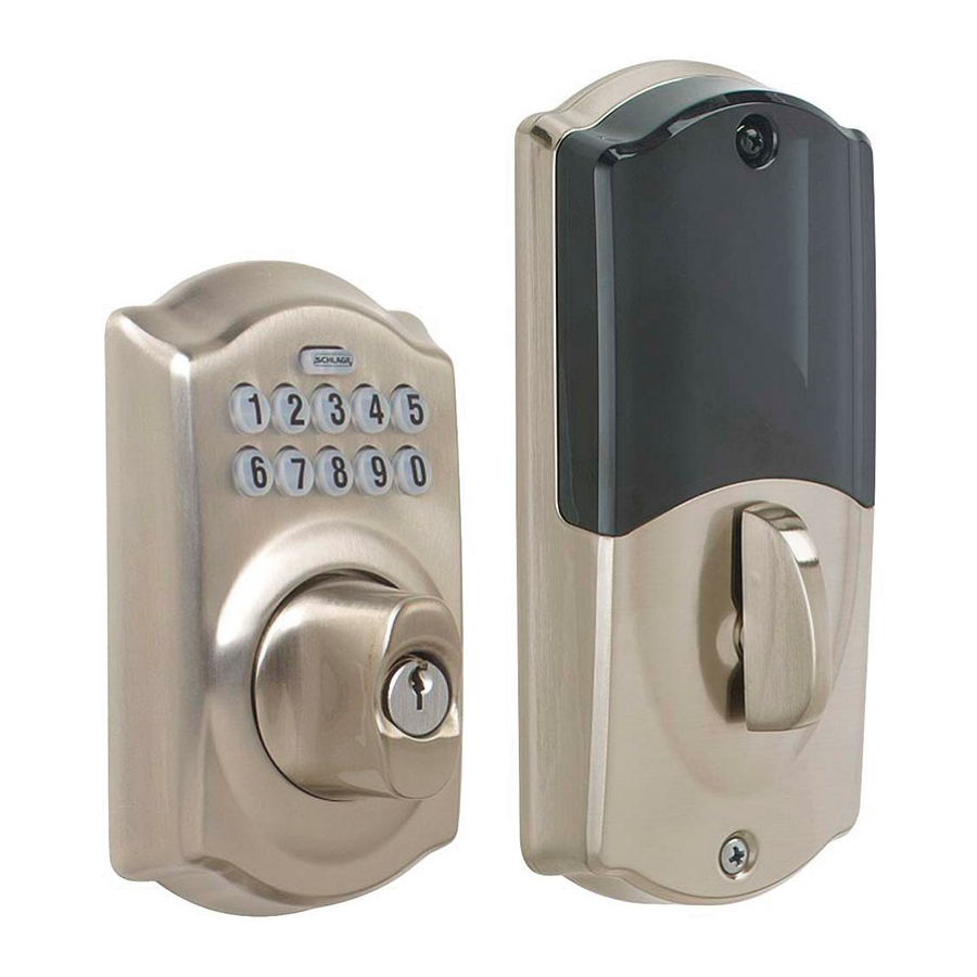
HOME KEYPAD LOCK
INSTALLATION INSTRUCTIONS
MODEL BE369
Need Help?
(888) 805-9837
(U.S.A./Canada)
2³⁄₈" (60 mm)
2³⁄₈" (60 mm)
2b. Check backset.
This lock will fit either a 2C\," backset or a 2C\v" backset. The bolt is preset to fit a 2C\," backset. If
your backset is not 2C\,", you need to adjust your bolt by rotating it counterclockwise.
2C\," (60 mm)
2C\v" (70 mm)
4
OR
4
2 ³⁄₄
4
Incorrect
4b. Connect cable.
Snap the connectors together. Tuck them into the open space in the
baseplate. Make sure no wires will be pinched when the cover is installed.
Actual Size (2)
6
6a. Prepare the frame for the strike.
Mark the 4 hole locations. Drill them as shown.
If the strike cut-out has not been prepared in the frame, see the specifications on the right.
Actual Size
Actual Size
To Lock
a. Press
b. Rotate turn towards door edge
a. Presione
b. Gire hacia el borde externo de la puerta
Did bolt extend?
a. Presser
b. tourner vers le bord de la porte
No. Lock is not installed correctly.
Remove lock and reinstall. Pay close
attention to cam position in step 3a.
Correct
Incorrect
Tools Needed
• Phillips screwdriver
• Tape Measure
OR
• Pencil
Optional
• Flathead Screwdriver
• Wood Block
• Hammer
Do not use a power
drill for installation
2³⁄₄" (70 mm)
2c. If necessary, change bolt faceplate
Check edge of door to determine the type of faceplate
required.
2 ³⁄₄
2 ³⁄₄
No change
OR
OR
necessary.
OR
2³⁄₄" (70 mm)
2³⁄₄" (70 mm)
3b. Install exterior keypad.
Bar should slide smoothly through hole in latch. If not, check door dimensions. Feed the cable over the
top of the bolt assembly then slide the tailpiece through the correct hole as shown below.
2 ³⁄₄
Exterior
Match arrows
!
Tailpiece
Las flechas deben quedar alineadas
Aligner les flèches
1"
(25 mm)
To Lock
Para cerrar
Pour verrouiller
a. Press
b. Rotate turn towards door edge
a. Presione
b. Gire hacia el borde externo de la puerta
a. Presser
b. tourner vers le bord de la porte
⁵⁄₃₂" x 3"
(4 mm x 76 mm)
2 Holes
7b. Test unlocking function.
Para cerrar
Pour verrouiller
1. Find User Code A on the yellow sticker.
2. Enter User Code A (four digits) into the keypad.
3. Rotate thumbturn away from door edge until bolt retracts.
Yes. Lock is installed correctly.
Contents
Baseplate
Screws (2)
Interior
Baseplate
Keypad
Key
Strike
Reinforcement
Screws (2)
2³⁄₄" (70 mm)
2d. Install bolt.
The word "TOP" should be facing upward.
OR
3c. Install the interior baseplate.
Feed the cable through the hole as shown below. DO NOT connect the cable at this
time. Then slide the baseplate onto the tailpiece and press against the door. The
baseplate should stay in place.
IMPORTANT
Cable must slide
over latch.
Tailpiece
4c. Install batteries.
1.
Unscrew battery holder.
2.
Slide out battery holder and install batteries.
3.
Attach 9 volt battery to battery connector.
4.
Place 9 volt battery in compartment.
Reinforcement
Screws
Install for maximum security.
6b. Install the strike.
Strike cut-out specifications
(not to scale)
1"
(25 mm)
1" (25
mm)
2³⁄₄"
1¹⁄₂"
(38 mm)
(70 mm)
¹⁄₈" (3 mm)
1¹⁄₈"
(29 mm)
⁵⁄₃₂" x 3"
⁵⁄₃₂" x 3"
(4 mm x 76 mm)
(4 mm x 76 mm)
2 Holes
2 Holes
Latch/Strike
Screws
Did bolt retract?
No. Lock is not installed correctly.
Remove lock and reinstall. Pay close
attention to cam position in step 3a.
Correct
Incorrect
Top Cover
Screw
Cover
OR
Bottom Cover
Screw
Top
Alternate
Faceplate
Latch/Strike
Screws (4)
AA Batteries (3)
not included
Strike
9 Volt Battery
Reinforcement
not included
Plate
Actual Size (2)
OR
Interior
2
1
4
3
1"
(25 mm)
Actual Size (2)
Actual Size (2)
Strike cut-out specifications
(not to scale)
1"
(25 mm)
This device complies with part 15 of the FCC rules. Operation is subject
to the following two conditions: (1) This device may not cause harmful
1¹⁄₂"
(38 mm)
interference, and (2) this device must accept any interference received,
including interference that may cause undesired operation.
Changes or modifications to this equipment not expressly approved by
¹⁄₈" (3 mm)
Schlage could void the user's authority to operate the equipment.
1¹⁄₈"
FCC ID: P2GBE369
IC: 7654A-BE369
(29 mm)
© Allegion 2014
Printed in U.S.A.
P516-085 09/14-d
(25
Reinforce
Screws
Install for maxim
2³⁄₄"
(70 mm)
Latch/Strike
Screws
Advertisement
Table of Contents

Related Manuals for Allegion BE369


Summary of Contents for Allegion BE369
- Page 1 HOME KEYPAD LOCK Contents *P516-085* INSTALLATION INSTRUCTIONS MODEL BE369 P516-085 Top Cover Baseplate Screw Screws (2) Cover Important Information Interior Tools Needed Baseplate Bottom Cover • Lock comes preset with a default Programming Code. • Phillips screwdriver Screw • Lock comes preset with two default User Codes •...
- Page 2 CERRADURA DEL TECLADO PARA EL HOGAR Contenido Contenu INSTRUCCIONES DE INSTALACIÓN MODELO BE369 Tornillos de la placa base (2) CLAVIER NUMÉRIQUE SERRURE Vis de la plaque de base (2) Tornillos de la cubierta Cubierta INSTRUCTIONS D’INSTALLATION Vis du couvercle Couvercle Herramientas necesarias MODÈLE BE369...
Need help?
Do you have a question about the BE369 and is the answer not in the manual?
Questions and answers