
Related Manuals for Pilz PNOZ m ES ETH


Summary of Contents for Pilz PNOZ m ES ETH
- Page 1 PNOZ m ES ETH Configurable Control System PNOZmulti Operating Manual1002700EN04...
- Page 2 Preface This document is a translation of the original document. All rights to this documentation are reserved by Pilz GmbH & Co. KG. Copies may be made for internal purposes. Suggestions and comments for improving this documentation will be gratefully received. Pilz®, PIT®, PMI®, PNOZ®, Primo®, PSEN®, PSS®, PVIS®, SafetyBUS p®, SafetyEYE®, SafetyNET p®, the spirit of safety® are registered and protected trademarks of Pilz GmbH & Co. KG in some countries. SD means Secure Digital...
-
Page 3: Table Of Contents
Content Section 1 Introduction Validity of documentation Retaining the documentation Definition of symbols Section 2 Overview Scope of delivery Unit features Front view Section 3 Safety Intended use System requirements Safety regulations 3.3.1 Use of qualified personnel 3.3.2 Warranty and liability 3.3.3 Disposal 3.3.4 For your safety Section 4 Function description Unit properties Block diagram Section 5 Installation General installation guidelines Dimensions Connecting the base unit and expansion modules Section 6 Commissioning General wiring guidelines Preparing for operation Download modified project to the PNOZmulti safety system Ethernet interfaces 6.4.1 RJ45 interfaces ("Ethernet") 6.4.2 Requirements of the connection cable and connector... -
Page 4: Operating Manual Pnoz M Es Eth
Introduction Introduction Validity of documentation This documentation is valid for the product PNOZ m ES ETH. It is valid until new document ation is published. This operating manual explains the function and operation, describes the installation and provides guidelines on how to connect the product. Retaining the documentation This documentation is intended for instruction and should be retained for future reference. Definition of symbols Information that is particularly important is identified as follows: DANGER! This warning must be heeded! It warns of a hazardous situation that poses an immediate threat of serious injury and death and indicates preventive measures that can be taken. WARNING! This warning must be heeded! It warns of a hazardous situation that could lead to serious injury and death and indicates preventive measures that can be taken. CAUTION! This refers to a hazard that can lead to a less serious or minor injury plus material damage, and also provides information on preventive measures that can be taken. NOTICE This describes a situation in which the product or devices could be dam aged and also provides information on preventive measures that can be taken. It also highlights areas within the text that are of particular import ance. Operating Manual PNOZ m ES ETH 1002700EN04... - Page 5 Introduction INFORMATION This gives advice on applications and provides information on special fea tures. Operating Manual PNOZ m ES ETH 1002700EN04...
-
Page 6: Overview
Overview Overview Scope of delivery Expansion modulePNOZ m ES ETH Jumper 779 260 Unit features Using the product PNOZ m ES ETH: Communication module for connection to a base unit from the configurable control system PNOZmulti 2. The product has the following features: Can be configured in the PNOZmulti Configurator 2 Ethernet interfaces Status indicators for supply voltage, communication and errors Max. 1 communication module can be connected to the left of the base unit PNOZmulti Please refer to the document "PNOZmulti System Expansion" for the PNOZmulti base units that can be connected Operating Manual PNOZ m ES ETH 1002700EN04... -
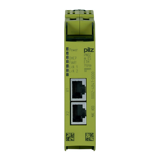
Page 7: Front View
Overview Front view Legend: X1, X2: Ethernet interfaces LEDs: – Power – DHCP – L/A 1 (Link/‘Act 1) – L/A 2 (Link/Act 2) Operating Manual PNOZ m ES ETH 1002700EN04... -
Page 8: Safety
Safety Safety Intended use The expansion module PNOZ m ES ETH is used for communication of the configurable con trol system PNOZmulti 2 via Ethernet. The expansion module may only be connected to a base unit from the configurable control system PNOZmulti 2 (please refer to the document "PNOZmulti System Expansion" for de tails of the base units that can be connected). The configurable control system PNOZmulti 2 is used for the safetyrelated interruption of safety circuits and is designed for use in: ESTOP equipment Safety circuits in accordance with VDE 0113 Part 1 and EN 602041 The expansion module may not be used for safetyrelated functions. Intended use includes making the electrical installation EMCcompliant. The product is de signed for use in an industrial environment. It is not suitable for use in a domestic environ ment, as this can lead to interference. The following is deemed improper use in particular: Any component, technical or electrical modification to the product Use of the product outside the areas described in this manual Use of the product outside the technical details (see chapter entitled “Technical De tails”) System requirements Please refer to the "Product Modifications" document in the "Version overview" section for details of which versions of the base unit and PNOZmulti Configurator can be used for this product. Safety regulations 3.3.1 Use of qualified personnel The products may only be assembled, installed, programmed, commissioned, operated, maintained and decommissioned by competent persons. A competent person is someone who, because of their training, experience and current pro fessional activity, has the specialist knowledge required to test, assess and operate the work equipment, devices, systems, plant and machinery in accordance with the general standards and guidelines for safety technology. It is the company’s responsibility only to employ personnel who: Are familiar with the basic regulations concerning health and safety / accident preven tion Have read and understood the information provided in this description under "Safety" And have a good knowledge of the generic and specialist standards applicable to the specific application. -
Page 9: Warranty And Liability
Safety 3.3.2 Warranty and liability All claims to warranty and liability will be rendered invalid if The product was used contrary to the purpose for which it is intended Damage can be attributed to not having followed the guidelines in the manual Operating personnel are not suitably qualified Any type of modification has been made (e.g. exchanging components on the PCB boards, soldering work etc.). 3.3.3 Disposal In safetyrelated applications, please comply with the mission time t in the safetyre lated characteristic data. When decommissioning, please comply with local regulations regarding the disposal of electronic devices (e.g. Electrical and Electronic Equipment Act). 3.3.4 For your safety The unit meets all necessary conditions for safe operation. However, you should always en sure that the following safety requirements are met: This operating manual only describes the basic functions of the unit. Information on the advanced functions can be found in the online help for the PNOZmulti Configurator and in the PNOZmulti technical catalogue. Only use these functions after you have read and understood the documentation. All necessary documentation can be found on the PNOZmulti Configurator CD. Do not open the housing or make any unauthorised modifications. Please make sure you shut down the supply voltage when performing maintenance work (e.g. exchanging contactors). Operating Manual PNOZ m ES ETH 1002700EN04... -
Page 10: Function Description
Function description Function description Unit properties The product PNOZ m ES ETH has two Ethernet interfaces to Download the project Read the diagnostic data Set virtual inputs for standard functions Read virtual outputs for standard functions via Ethernet (TCP/IP, Modbus/TCP). Information on diagnostics via the Ethernet interfaces can be found in the document entitled " PNOZmulti 2 communication interfaces". The connection to Ethernet is made via the two 8pin RJ45 sockets. The Ethernet interface is configured in the PNOZmulti Configurator and is described in the online help for the PNOZmulti Configurator. Block diagram Operating Manual PNOZ m ES ETH 1002700EN04... -
Page 11: Installation
Installation Installation General installation guidelines The unit should be installed in a single mounting area with a protection type of at least IP54. Fit the safety system to a horizontal mounting rail. The venting slots must face upwards and downwards. Other mounting positions could destroy the safety system. Use the locking slide on the rear of the unit to attach it to a mounting rail. In environments exposed to heavy vibration, the unit should be secured using a fixing element (e.g. retaining bracket or end angle). Open the locking slide before lifting the unit from the mounting rail. To comply with EMC requirements, the mounting rail must have a low impedance con nection to the control cabinet housing. The ambient temperature of the PNOZmulti units in the control cabinet must not exceed the figure stated in the technical details, otherwise air conditioning will be required. CAUTION! Damage due to electrostatic discharge! Electrostatic discharge can damage components. Ensure against discharge before touching the product, e.g. by touching an earthed, conductive sur face or by wearing an earthed armband. Dimensions 22,5 101,4 (4,11“) (0,88“) Connecting the base unit and expansion modules Connect the base unit and the expansion module as described in the operating instructions for the base units. Install the expansion module in the position in which it is configured in the PNOZmulti Configurator. Operating Manual PNOZ m ES ETH 1002700EN04... - Page 12 Installation Connect the base unit and expansion modules using the yellow/black jumper. Connect the black/yellow terminator to the expansion module. Operating Manual PNOZ m ES ETH 1002700EN04...
-
Page 13: Commissioning
Commissioning Commissioning General wiring guidelines The wiring is defined in the circuit diagram of the PNOZmulti Configurator. Please note: Information given in the "Technical details" must be followed. Use copper wire that can withstand 75°C. Preparing for operation Detection and activation of the Ethernet interface, depending on the USB interface on the base unit: USB interface on the base unit not connected If the USB interface on the base unit is not connected, the Ethernet interface will be de tected and activated by the base unit as soon as the communication module has been connected to the base unit. USB interface on the base unit connected If the USB interface on the base unit is already connected, the "Ethernet" interface will first need to be selected on the base unit display to enable the Ethernet interface on the base unit to be detected and activated (see operating manual for the base unit for de tails of the setting). Download modified project to the PNOZmulti safety system As soon as an additional expansion module has been connected to the system, the project must be amended using the PNOZmulti Configurator. Proceed as described in the operat ing instructions for the base unit. NOTICE For the commissioning and after every program change, you must check whether the safety devices are functioning correctly. Ethernet interfaces 6.4.1 RJ45 interfaces ("Ethernet") Two free switch ports are provided as Ethernet interfaces via an internal autosensing switch. The autosensing switch automatically detects whether data transfer is occurring at 10 Mbit/s or 100 Mbit/s. Operating Manual PNOZ m ES ETH 1002700EN04... -
Page 14: Requirements Of The Connection Cable And Connector
Commissioning INFORMATION The connected subscribers must support the autosensing/autonegotiation function. If not, the communication partner must be set permanently to "10 Mbit/s, half duplex". The switch's automatic crossover function means there is no need to distinguish on the connection cable between patch cable (uncrossed data line connection) and crossover cable (crossover data line connection). The switch automatically creates the correct data line connection internally. Patch cable can therefore be used as the connection cable for end devices as well as cascading. Both Ethernet interfaces use RJ45 technology. 6.4.2 Requirements of the connection cable and connector The following minimum requirements must be met: Ethernet standards (min. Category 5) 10BaseT or 100BaseTX Doubleshielded twisted pair cable for industrial Ethernet use Shielded RJ45 connectors (industrial connectors) 6.4.3 Interface configuration RJ45 socket 8pin Standard Crossover TD+ (Transmit+) RD+ (Receive+) TD (Transmit) RD (Receive) RD+ (Receive+) TD+ (Transmit+) n.c. n.c. n.c. n.c. RD (Receive) TD (Transmit) n.c. n.c. n.c. n.c. Operating Manual PNOZ m ES ETH 1002700EN04... -
Page 15: Rj45 Connection Cable
Commissioning 6.4.4 RJ45 connection cable RJ45 connector 8pin 10BaseT cable or 100BaseTX cable max. 100 m NOTICE With the plugin connection please note that the data cable and connector have a limited mechanical load capacity. Appropriate design measures should be used to ensure that the plugin connection is insensitive to in creased mechanical stress (e.g. through shock, vibration). Such measures include fixed routing with strain relief, for example. Operating Manual PNOZ m ES ETH 1002700EN04... -
Page 16: Process Data Exchange
Commissioning 6.4.5 Process data exchange The RJ45 interfaces on the internal autosensing switch enable process data to be ex changed with other Ethernet subscribers within a network. The product PNOZ m ES ETH can also be connected to Ethernet via a hub (hub or switch). Ethernet subscriber Ethernet subscriber PC with PNOZmulti Configurator Base unit PNOZmulti2 + communications module with Ethernet interface Base unit PNOZmulti2 + communications module with Ethernet interface Operating Manual PNOZ m ES ETH 1002700EN04... -
Page 17: Operation
Operation Operation When the supply voltage is switched on, the PNOZmulti safety system copies the configur ation from the chip card. The LEDs "POWER","DIAG", "FAULT", "IFAULT" and "OFAULT" light up on the base unit. The safety system PNOZmulti is ready for operation when the "POWER" and "RUN" LEDs on the base unit and the "POWER" LED on the PNOZ m ES ETH are lit continuously. Messages Legend: LED on LED flashes LED off LED status Meaning Power No supply voltage Green Supply voltage is present L/A 1 ( Link / Act 1 ) No network connection at X1 / No data traffic at X1 Green Network connection present at X1 / Data traffic present at X1 L/A 2 ( Link / Act 2 ) No network connection at X2 / No data traffic at X2 Green Network connection present at X2 / Data traffic present at X2 Fault Internal fault No connection to base unit DHCP Yellow The unit could not be assigned an IP address by the DHCP Server. Yellow The unit is waiting for the DHCP Server to assign an IP address Operating Manual PNOZ m ES ETH 1002700EN04... -
Page 18: Reset Ethernet Connection Settings
Operation Reset Ethernet connection settings The Ethernet connection settings of the base unit can be configured in the PNOZmulti Con figurator. You can reset the base unit's Ethernet connection settings to the default settings. Proceed as follows: Switch off the supply voltage Remove the chip card Restart the base unit without the chip card inserted. The Ethernet connection settings are now reset to the default settings. Operating Manual PNOZ m ES ETH 1002700EN04... -
Page 19: Tecnical Details
Tecnical details Tecnical details General 772130 Approvals CCC, CE, GOST, cULus Listed Application range Standard Module's device code 1202h Electrical data 772130 Supply voltage Module supply internal Via base unit Voltage 5,0 V Kind Voltage tolerance 2 %/+2 % Current consumption 295 mA Power consumption 1,0 W Status indicator Ethernet interface 772130 Number IP address (automatically off) 169.254.60.1 Connection type RJ45 Transmission rate 10 MBit/s, 100 MBit/s Fieldbus interface 772130 Fieldbus interface Modbus TCP Unit type Slave Connection RJ45... - Page 20 Tecnical details Environmental data 772130 Shock stress In accordance with the standard EN 60068227 Acceleration Duration 11 ms Max. operating height above sea level 2000 m Airgap creepage In accordance with the standard EN 611312 Overvoltage category Pollution degree Rated insulation voltage 30 V Protection type In accordance with the standard EN 60529 Mounting area (e.g. control cabinet) IP54 Housing IP20 Terminals IP20 Mechanical data 772130 Mounting position Horizontal on top hat rail DIN rail Top hat rail 35 x 7,5 EN 50022 Recess width 27 mm Max. cable length Max. cable length per input 0,1 km Material Bottom Front Dimensions...
-
Page 21: Order Reference
Order reference Order reference Module Product type Features Order no. PNOZ m ES ETH Expansion module 772 130 Accessories Terminator, jumper Product type Features Order no. PNOZ mm0.xp connector Jumper yellow/black to connect the modules, 1 piece 779 260 left Operating Manual PNOZ m ES ETH 1002700EN04... -
Page 22: Technical Support
+49 711 3409-444 represented by our subsidiaries support@pilz.com and sales partners. Please refer to our homepage for further details or contact our headquarters. Pilz GmbH & Co. KG Felix-Wankel-Straße 2 73760 Ostfildern, Germany Telephone: +49 711 3409-0 Telefax: +49 711 3409-133 E-Mail: pilz.gmbh@pilz.de...
Need help?
Do you have a question about the PNOZ m ES ETH and is the answer not in the manual?
Questions and answers