Table of Contents
Advertisement
Quick Links
Advertisement
Table of Contents

Related Manuals for Westermo Viper 408


Summary of Contents for Westermo Viper 408
- Page 1 Viper 408 Managed 8-port Ethernet Switch...
- Page 2 6641-2201...
-
Page 3: General Information
Under no circumstances shall Westermo be responsible for any loss of data or income or any special, incidental, and consequential or indirect damages howsoever caused. -
Page 4: Safety And Regulations
Safety and Regulations Warning signs are provided to prevent personal injury and/or damages to the product. The following levels are used: Level of warning Description Consequence Consequence personal injury material damage Indicates a potentially Possible death or Major damage to the hazardous situation major injury product... -
Page 5: Before Installation
During installation, ensure a protective earthing conductor is first connected to the protective earthing terminal (only valid for metallic housings). Westermo recommends a cross-sectional area of at least 4 mm2. Upon removal of the product, ensure that the protective earthing conductor is disconnected last. - Page 6 CAUTION - HOT SURFACE Be aware that the surface of this product may become hot. When it is operated at high temperatures, the external surface may exceed Touch Temperature Limit according to the product's relevant electrical safety standard. CAUTION - ELECTROSTATIC DISCHARGE (ESD) Prevent electrostatic discharge damages to internal electronic parts by discharging your body to a grounding point (e.g.
-
Page 7: Care Recommendations
If the product is used in a manner not according to specification, the protection provided by the equipment may be impaired. If the product is not working properly, contact the place of purchase, nearest Westermo distributor office or Westermo technical support. -
Page 8: Agency Approvals And Standards Compliance
Agency approvals and standards compliance Type Approval / Compliance EN 61000-6-1, Immunity residential environments EN 61000-6-2, Immunity industrial environments EN 61000-6-3, Emission residential environments EN 61000-6-4, Emission industrial environments EN 50121-3-2, Railway applications - EMC: Rolling stock – Apparatus EN 50121-4, Railway signalling and telecommunications apparatus IEC 62236-4, Railway signalling and telecommunications apparatus E-Mark, Road Vehicles, E1 no: 10 R - 047216 Environmental... -
Page 9: Type Tests And Environmental Conditions
Type tests and environmental conditions Phenomena Test Description Test levels EN 61000-4-2 Enclosure contact ± 6 kV (crit A) Enclosure air ± 8 kV (crit A) RF field AM modulated IEC 61000-4-3 Enclosure 20 V/m 80% AM (1 kHz), 80 – 2700 MHz (crit A) 10 V/m 80% AM (1 kHz), 2700 –... - Page 10 Phenomena Test Description Test levels Shock, half sine pulses IEC 60068-2-27, Operating Vertical: 50 m/s Cat. 1 class B Transverse: 50 m/s (EN 61373) Longitudinal: 50 m/s 30 ms, 3 x 6 shocks Shock, sawtooth IEC 60068-2-27, Operating Vertical: 100 m/s Cat.
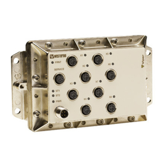
- Page 11 Description Functional description Viper-408 is a switch developed for rail and industrial applications. To meet the environmental requirements from rail and harsh industrial applications the switch has rugged M12 Ethernet connectors and full metal housing. The switch fullfill IP65 degree of protection when all ports are protected/connected.
-
Page 12: Interface Specifications
Interface specifications Power and fault relay port PWR Rated voltage 24 to 110 VDC Operating voltage 16.8 to 143 VDC (14.4 to 154 for 100 ms) Rated current 140 mA @ 24 VDC 40 mA @ 110 VDC Rated frequency Inrush current, I Max 0.02 A s @ 24 –... -
Page 13: Fault Contact
To logic input +24/48 VDC Viper Viper 1 kΩ Input on PLC Service port The service port should not be used by non other than the Westermo technical support team. Do not connect any device or cable to the service port. 6641-2201... - Page 14 Ethernet TX port X1 to X8 Electrical specification IEEE std 802.3. 2000 Edition Data rate 10 Mbit/s or 100 Mbit/s, manual or auto Duplex Full or half, manual or auto Circuit type TNV-1 Transmission range 150 m Isolation to Other Ethernet ports, 500 VAC PWR, 1500 VAC Galvanic connection to None, except for shielded contact to housing...
- Page 15 Location of Interface ports, LEDs LED indicators Status Description GREEN Unit indicates no fault Unit indicated fault FLASH Connected to IP Configuration tool FRNT FRNT is not enabled or not supported GREEN FRNT is running and the switch is configured as member switch in the ring.
- Page 16 The units can easily be configured via the onboard Web based configuration tool. Local IP addresses can also be configured by using the Westermo IP Configuration tool, from the IP Configuration tool it is then possible to browse into the unit for further configuration.
- Page 17 By clicking the “Scan for Devices” button the IP Configuration tool will detect the switches/routers in the network. The software will list all Westermo managed switches or routers connected to the network. Information as in the figure 1 will appear for each detected unit connected to the same network as your PC.
- Page 18 Log in via Web Westermo - location - Provided by Westermo http://192.168.2.220/conf/p.cgi Google You will be prompted with a Login screen where File Edit View Favorites Tools Help the default settings for Username and Password are: Home Feeds (J) Feeds (J)
- Page 19 Mounting There are four 6 mm bore holes intended for mounting the unit. The unit can be mounted vertical or horizontal. The unit is wall mounted. FRNT SERVICE Removal Disconnect all cables and unscrew the unit from the wall. Cooling This unit uses convection cooling.
-
Page 20: Factory Reset
• All Ethernet ports are enabled and set to Auto Negotiate • All applications are disabled • Password reset to westermo To perform a Factory Reset follow the procedure below. Read all steps before starting. If you have any doubts whether the reset is performed or not, do NOT unplug the power supply, wait for confirmation according to step 5. - Page 21 Dimensions Measurements are stated in millimeters. 175 ±1 53,4 ±1 164 ±1 41,5 ±1 142 ±1 22,7 ±1 3,9 ±0,3 6,5 ±0,2(4x) 55,6 37,2 18,8 6641-2201...
- Page 22 Westermo • Metallverksgatan 6, SE-721 30 Västerås, Sweden Tel +46 16 42 80 00 Fax +46 16 42 80 01 E-mail: info@westermo.com www.westermo.com REV. M 6641-2201 2021-08 Westermo Network Technologies AB, Sweden...
Need help?
Do you have a question about the Viper 408 and is the answer not in the manual?
Questions and answers