Table of Contents
Advertisement
Quick Links
Advertisement
Table of Contents

Related Manuals for Westermo Viper-012


Summary of Contents for Westermo Viper-012
- Page 1 Viper-012 Unmanaged EN 50155 Switch...
- Page 2 6641-22410...
-
Page 3: General Information
Under no circumstances shall Westermo be responsible for any loss of data or income or any special, incidental, and consequential or indirect damages howsoever caused. -
Page 4: Safety And Regulations
Safety and Regulations Warning signs are provided to prevent personal injury and/or damages to the product. The following levels are used: Level of warning Description Consequence Consequence personal injury material damage Indicates a potentially Possible death or Major damage to the hazardous situation major injury product... -
Page 5: Before Installation
During installation, ensure a protective earthing conductor is first connected to the protective earthing terminal (only valid for metallic housings). Westermo recommends a cross-sectional area of at least 4 mm2. Upon removal of the product, ensure that the protective earthing conductor is disconnected last. - Page 6 CAUTION - HOT SURFACE Be aware that the surface of this product may become hot. When it is operated at high temperatures, the external surface may exceed Touch Temperature Limit according to the product's relevant electrical safety standard. CAUTION - ELECTROSTATIC DISCHARGE (ESD) Prevent electrostatic discharge damages to internal electronic parts by discharging your body to a grounding point (e.g.
-
Page 7: Care Recommendations
If the product is used in a manner not according to specification, the protection provided by the equipment may be impaired. If the product is not working properly, contact the place of purchase, nearest Westermo distributor office or Westermo technical support. -
Page 8: Agency Approvals And Standards Compliance
Agency approvals and standards compliance Type Approval / Compliance EN 61000-6-1, Immunity residential environments EN 61000-6-2, Immunity industrialokokvironments EN 61000-6-3, Emission residential environments EN 61000-6-4, Emission industrial environments EN 50121-3-2, Railway applications – Rolling stock – apparatus EN 50121-4/IEC 62236-4, Railway signaling and telecommunications apparatus Environmental EN 61373, Railway applications –... -
Page 9: Type Tests And Environmental Conditions
Type tests and environmental conditions Environmental phenomena Basic standard Description Test levels EN 61000-4-2 Enclosure Contact: ±6 kV Air: ±8 kV Fast transients EN 61000-4-4 Power port ±5 kV Signal ports ±2 kV Earth port ±1 kV Surge EN 61000-4-5 Power port L-E: ±2 kV, 12Ω, 9 μF, 1.2/50 μs L-L: ±1 kV, 2Ω, 18 μF, 1.2/50 μs... - Page 10 Description Designed for harsh industrial environments The Viper-012 is a unmanaged rugged Ethernet switch designed for applications with severe operating conditions and extreme environments. With an ultra robust design, sealed to IP67 and vibration resistant to and exceeding on-board rail standards this unit is ideal for situations where mechanical stress, moisture, condensation, dirt or continuous vibrations could adversely affect the function of standard Ethernet switches.
-
Page 11: Interface Specifications
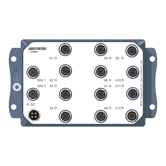
Viper-x12-T3G: X1-X3, X5-X7, X9-X11: 1500 VAC rms to other ports X4, X8, X12: 500 VAC rms to other ports Connection 4-pin M12 D-code, auto MDI/MDI-X, use e g Westermo cable 3146-1100 M12-M12 – 1 m 3146-1101 M12-M12 – 5 m 3146-1103 RJ45-M12 – 1 m 3146-1104 RJ45-M12 –... - Page 12 Location of interface ports and LED Ethernet connection TX LED indicators Westermo internal use only SRV 1 SRV 2 Power connection Earth connection 6641-22410...
-
Page 13: Power Connector Pin-Out
Power failure on DC1 or DC2. X1 to No Link. SRV 1 GREEN Link established. SRV 2 GREEN Data traffic indication. FLASH YELLOW Port alarm and no link. SRV 1 & SRV 2 only for internal use by Westermo staff 6641-22410... -
Page 14: Wall Mounting
Wall mounting There are four 6 mm bore holes intended for mounting the unit. The unit can be mounted vertical or horizontal. Use four M5 screws with 12 mm washer on a flat and stable surface. SRV 1 SRV 2 Connection of cables Recommended tightening torque for the M12 connectors: 0.6 Nm Note that unused connectors must be covered by a protective cap (delivered with the... - Page 15 Dimensions Measurements are stated in millimeters. Description Date Designer Approved Created 130225 PaPu ToDu 174 ±1 164 ±1 65,4 ±1 11 ±1 142 ±1 54,1 ±1 73,5 48,8 23,3 6,7 ±1 6,5 - 0,5(4x) Pos No Quantity Description Designation / Dimension Material / Remark Designer Approved...
- Page 16 Westermo • SE-640 40 Stora Sundby, Sweden Tel +46 16 42 80 00 Fax +46 16 42 80 01 E-mail: info@westermo.com www.westermo.com REV. B 6641-22410 2021-06 Westermo Network Technologies AB, Sweden...
Need help?
Do you have a question about the Viper-012 and is the answer not in the manual?
Questions and answers