Table of Contents
Advertisement
Quick Links
Advertisement
Table of Contents

Related Manuals for Belden ThinkLogical TLX12


Summary of Contents for Belden ThinkLogical TLX12
- Page 1 Rev. E, Oct. 2019...
- Page 2 Page ii Copyright Notice Copyright © 2019. All rights reserved. Printed in the U.S.A. Thinklogical, A BELDEN BRAND 100 Washington Street Milford, Connecticut 06460 U.S.A. Telephone: 1-203-647-8700 All trademarks and service marks are property of their respective owners. Subject: TLX12 10G Matrix Switch Product Manual Revision: E, October 2019 ®...
-
Page 3: Table Of Contents
Page iii Table of Contents PREFACE..............................v About Thinklogical ........................v ® About This Product Manual ......................vi Note and Warning Symbols ...................... vi Class 1 Laser Information ......................vi SECTION 1: TLX SYSTEM FEATURES ....................1 The TLX12 Matrix Switch Design ....................2 Ordering Information ........................ - Page 4 Page iv SECTION 3: REGULATORY & SAFETY REQUIREMENTS ..............20 Symbols Found on Our Products ....................20 Regulatory Compliance ......................20 North America ........................20 Australia & New Zealand ......................20 European Union ........................20 Declaration of Conformity ....................20 Standards with Which Our Products Comply ................
-
Page 5: Preface
Thinklogical products are designed and manufactured in the USA and are certified to the ISO 9001:2015 standard. Thinklogical is headquartered in Milford, Connecticut and is owned by Belden, Inc., St. Louis, MO (http://www.belden.com). For more information about Thinklogical products and services, please visit https://www.thinklogical.com. -
Page 6: About This Product Manual
Page vi About this Product Manual This product manual is divided into four sections: TLX System Features, Set-Up & Installation, Regulatory & Safety Requirements and Thinklogical Support. These are sub-divided to help you find the topics and procedures you are looking for. This manual also contains Appendices. Section 1 –... -
Page 7: Section 1: Tlx System Features
Page 1 Section 1: TLX System Features The Logical Solution The TLX12 is an ultra-compact 10G high performance non-blocking matrix switch that supports full, uncompressed 4K video with full color depth at 60Hz frame rate for complete, end-to-end routing of video and peripheral signals over multi-mode or single-mode fiber-optic cable in a single 1 RU Chassis. -
Page 8: The Tlx12 Matrix Switch Design
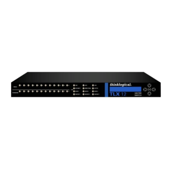
Page 2 THE TLX12 MATRIX SWITCH DESIGN The ultra-compact design of the TLX12 10G Matrix Switch (sometimes referred to as a Switch or Router) supports up to 12 ports of full, uncompressed 4K video with full color depth at 60Hz frame rate in a single 1 RU chassis for complete, end-to-end routing of video and peripheral signals over multi-mode or single- mode fiber-optic cable or CATx cable, thus minimizing critical rack space. -
Page 9: Design Features
Page 3 DESIGN FEATURES Each TLX12 includes the following features: • 12 fiber or 12 CATx ports - In and Out, non-blocking matrix switching • Each connection supports 10Gbps / 6.25 Gbps with re-clocking input • Single-mode, multi-mode fiber and BNC coaxial capability •... -
Page 10: Navigating The Menus
Page 4 Navigating the Menus Main Root Menus: Once the system is powered up, the initial chassis display is shown as follows: Your Host Name TLX12 Matrix Switch V1.02 Your chosen Host Name is listed on the first line of the display. The model and software version (VX.XX) of the unit are displayed on the second line. - Page 11 Page 5 SOURCES 1-12 Used to select any one of the 12 Matrix Switch inputs. Only one input can be selected per action. (Pressing a button illuminates it to confirm the selection.) A previously selected input will be deselected upon selecting a new input. To deselect, Source 1 is connected to simply press the illuminated button and the button shall no longer Destinations 1, 2 &...
-
Page 12: The Power Supply Module
Page 6 SNAPSHOT n When in LOCK mode, holding one of the SNAPSHOT buttons for >5 seconds will capture the full connection map including those DESTINATION(S) that are disconnected. When in NORMAL mode, pressing that SNAPSHOT button will replace all the connections with the SNAPSHOT connection map (not an additive action). -
Page 13: The Network Interfaces
Page 7 THE NETWORK INTERFACES The default subnet used by the TLX12 is 192.168.13.xxx. Users may change to their own subnet by reconfiguring the switch’s network startup. This is detailed in the document: Manual_How_To_Change_A_TLX_Matrix_Switch’s_IP_Address The switch uses several network ports for control and status. Port 17567 accepts commands to control the switch. -
Page 14: Ntp Support
Page 8 /etc/hosts The default name used by trap2sink is 'snmp.trap' and is defined in the file as pointing to /etc/hosts 127.0.0.1. The easiest method to change the trap address is to modify the entry and not change the trap2sink setting in the configuration file. Users may have multiple trap2sink entries in the configuration file to specify multiple trap destinations. -
Page 15: The Digital Crosspoint Switch
Page 9 THE DIGITAL CROSSPOINT SWITCH The Digital Crosspoint Switch is a non-blocking, asynchronous switch that can connect any input to any output of Thinklogical’s TLX, VX and MX Matrix Switches. Video and Data signals are routed in both directions and the data stream is de-multiplexed at the receiver to deliver uncompressed, high resolution video, audio and peripheral data at the end-user’s workstation. -
Page 16: Section 2: Set-Up And Installation
Page 10 Section 2: Set-Up & Installation Contents When you receive your Thinklogical TLX12 KVM Matrix Switch, you should find the following ® items in the quantities specified in your order: • TLX12 Chassis (includes 1 Power Module) • Power Cord – PWR-000006-R (International connections may differ) •... -
Page 17: External Control Cpu Minimum Requirements
Page 11 External Control CPU Minimum Requirements The External Control CPU must meet the following minimum requirements (including requirements for using Thinklogical’s System Management Portfolio): • System Management Interface package requires Debian 32 or 64 bit. • Configurator and Hot Key Manager run on Linux (RedHat 32 & 64 bit, Debian 32 &... -
Page 18: Fiber-Optic Cable
Page 12 LC-Type Fiber-Optic Cable Installing Fiber-Optic Cable: The TLX12 switching matrix connects any SFP’s optical OPTICAL OUTPUT PORT (Transmit) output port (Transmit) to any other SFP’s optical OPTICAL INPUT PORT (Receive) input port (Receive) with LC-type connectors. Requirements: Thinklogical recommends LC-type, SX+ Laser Enhanced (50 or 62.5µm) fiber for your TLX12 KVM Matrix Switch and Velocity Extension System. -
Page 19: Tlx Extender Fiber-Optic Cable Configurations
Page 13 TLX Extender Fiber-Optic Cable Configurations INGLE VIDEO MODULES DUAL VIDEO MODULES Note: On Dual Video models, SFPs 1 & 2 are Video 1 and SFPs 3 & 4 are Video 2. thinklogical TLX12 Matrix Switch Product Manual Rev. E, Oct., 2019... -
Page 20: Tlx Extender Catx Cable Configurations
Page 14 TLX Extender CATx Cable Configurations There are currently several versions of CATx (category 5/5a/6/6a/etc.) cables on the market. Thinklogical recommends using a minimum of CAT6 for your TLX KVM Matrix Switch and Extension System (CAT6a 23 AWG recommended). All cables CAT6 or higher can extend up to a maximum of 100m. -
Page 21: Routing Thinklogical Extenders Through The Tlx12
Page 15 Routing Thinklogical Extenders through the TLX12 Comprised of a fiber-optic or CATx Matrix Switch and fiber-optic or CATx Transmitter and Receiver Extenders, this complete system provides transparent and secure routing, switching and extension of video and high-speed data peripherals to remote destinations with ease. TLX Matrix Switch Transmit / Receive Concept Connecting to a Receiver The Velocity Receiver serves as the Destination (desktops, theaters, conference rooms, editing... -
Page 22: Product Combatability
Page 16 Routing Thinklogical TLX Extenders through the TLX12 ® Connecting to a Control CPU The TLX12 is controlled via a dedicated external Control CPU. This allows for customization as well as ease of control and administration. Access is provided via a network connection or serial RS-232 port. Note: The Control CPU (Computer) is supplied separately. -
Page 23: Linux Command Console (Console)
Page 17 Linux Command Console (Console) • Baud Rate: 115200 • Data Bits: 8 • Parity: none • Stop Bits: 1 • Flow Control: none • DB9 DCE ➢ A straight (NOT a null-modem) cable is needed to connect to a PC. ASCII API (RS-232) Settings •... -
Page 24: System Reboot Or Power Off At The Chassis
Page 18 System Reboot or Power Off at the Chassis From the Chassis’ LCD Main Menu, press the down arrow 4 times to get to Reboot/Power Off. Your Host Name TLX12 Matrix Switch V1.02 From the Reboot/Power Off menu, press the arrow once to choose Reboot or twice to Poweroff. Press ... -
Page 25: How To Remove And Replace A Power Supply
Page 19 How to Remove and Replace a Power Supply The Power Module is universal input 100-240VAC, 50-60Hz. Use the proper power cords for your region (PWR-000006-R, supplied with the unit). See the Power Off procedure, above. Perform a Poweroff as shown, previous page. Ensure the power cord is removed from the power supply module. -
Page 26: Section 3: Regulatory & Safety Requirements
European Union Declaration of Conformity Manufacturer’s Name & Address: Thinklogical, A BELDEN BRAND 100 Washington Street Milford, Connecticut 06460 USA Thinklogical’s products comply with the requirements of the Low Voltage Directive 2006/95/EC, the EMC Directive 2004/108/EC, the RoHS Directive 2011/65/EU, the WEEE Directive... -
Page 27: Supplementary Information
Page 21 Electromagnetic Immunity EN 55024:2011+A1 CENELEC EN 55032:2015 EN 61000-3-2:2000 Harmonics EN 61000-3-3:2008 Flicker EN 61000-4-2:2009 Electro-Static Discharge Test EN 61000-4-3:2006 A1:2008, A2:2010 Radiated Immunity Field Test EN 61000-4-4:2004 Electrical Fast Transient Test EN 61000-4-5:2006 Power Supply Surge Test EN 61000-4-6:2009 Conducted Immunity Test EN 61000-4-11:2004 Voltage Dips &... -
Page 28: Section 4: How To Contact Us
1-203-647-8700 and let us help. If you need to write us or return a product, please use the following address: Please include the Return Merchandise Authorization number: Thinklogical, A BELDEN BRAND 100 Washington Street Milford, CT 06460 USA Attn: RMA#... -
Page 29: Appendix A: Tlx12 Quick Start Guide
Page 23 Appendix A: TLX12 Quick Start Guide thinklogical TLX12 Matrix Switch Product Manual Rev. E, Oct., 2019... -
Page 30: Appendix B: Fpga Program Update Procedure
Page 24 Appendix B: TLX12 FPGA Program Code Update Procedure thinklogical TLX12 Matrix Switch Product Manual Rev. E, Oct., 2019... -
Page 31: Appendix C: Secure Applications
Page 25 Appendix C: Secure Applications TLX12 Matrix Switch Control When used in a secure application, the Matrix Switch and External Computer (server) used to manage the system must be in a physically secure environment to which only trusted administrators have access. Similarly, the server used to manage the Matrix Switch must be physically protected and have suitable identification/authentication mechanisms to ensure that only trusted administrators have access. - Page 32 Page 26 Restricted Switching Restricted Switching provides multiple levels of security classification domains on the same Matrix Switch. Each destination must ensure that no unauthorized content is displayed or accessed. Therefore, every input and output must be prioritized. Priorities can range from 1 to the total number of ports in the Matrix Switch.
- Page 33 Page 27 There are cases where updates to the Restricted Switching Table must be made in an active system. When an update is made to the table, the processor will not evaluate the updated table until the LAN connection is restored. Restricted Switching is disabled when Restricted Switching Table files are removed.
- Page 34 Page 28 Partitioning Partitions allow TLX, VX and MX Matrix Switch sources and destinations to be segregated. Therefore, destination work stations will only receive signals that are transmitted from source computers in the same partition. In addition, it is impossible for a source computer to be inadvertently routed outside of its designated partition as the signals will not be transmitted.
- Page 35 Page 29 At system power up, after initial boot-up, the processor will only evaluate its Partition Table (upstream.csv file) once upon becoming active. If an upstream.csv file is found, a log entry to the deamon.log file is made indicating “Partition ENABLED.” If no file is found, then a log entry of “Partition DISABLED”...
- Page 36 Page 30 Secure Application Examples The Diagram on pg. 31 shows the TLX12 Matrix Switch in a secure application. The highly secure components are described as the Red Network and the other, lower security components are described as the Black Network. The Red Network, containing the computers (sources), is shown in a physically secure environment along with the TLX Matrix Switch, the computer server used to manage the Switch, and the Network Hub.
- Page 37 Page 31 TLX12 Matrix Switch Secure Application thinklogical TLX12 Matrix Switch Product Manual Rev. E, Oct., 2019...
Need help?
Do you have a question about the ThinkLogical TLX12 and is the answer not in the manual?
Questions and answers