Raymarine ST60 Tridata Instrument Owner's Handbook Manual
Hide thumbs
Also See for ST60 Tridata Instrument:
- User manual ,
- Owner's handbook manual (58 pages) ,
- Operating manual (38 pages)

Related Manuals for Raymarine ST60 Tridata Instrument


Summary of Contents for Raymarine ST60 Tridata Instrument
- Page 1 81040_5.book Page 1 Monday, February 20, 2006 2:39 PM ST60 Tridata Instrument Owner’s Handbook Document number: 81040-5 Date: February 2006...
- Page 2 81040_5.book Page 2 Monday, February 20, 2006 2:39 PM Raymarine, ST60 and SeaTalk are trademarks of Raymarine UK Ltd © Handbook contents copyright Raymarine UK Ltd...
-
Page 3: Emc Conformance
The Waste from Electrical and Electronic Equipment (WEEE) Directive requires the recycling of waste electrical and electronic equipment. Whilst the WEEE Directive does not apply to some of Raymarine’s products, we support its policy and ask you to be aware of how to dispose of this product. -
Page 4: Handbook Information
Handbook information To the best of our knowledge, the information in this handbook was correct when it went to press. However, Raymarine cannot accept liability for any inaccuracies or omissions it may contain. In addition, our policy of continuous product improvement may change specifications without notice. -
Page 5: Table Of Contents
81040_5.book Page iii Monday, February 20, 2006 2:39 PM Contents Important information ..................i Safety notices ..................i EMC conformance ................i Handbook information ................ i Introduction ......................vii Data inputs ..................vii SeaTalk ....................vii Stand alone operation ..............viii Remote control .................viii Mounting options ................viii Parts supplied .................. - Page 6 81040_5.book Page iv Monday, February 20, 2006 2:39 PM ST60 Tridata Instrument Owner’s Manual Fault finding ..................10 Preliminary procedures ..............10 Fixing faults ..................10 Technical support ................11 World wide web ................11 Telephone help line ..............11 Help us to help you ..............12 Chapter 3: Installation ..................13...
- Page 7 81040_5.book Page v Monday, February 20, 2006 2:39 PM Set temperature units ..............33 Temperature calibration ............. 33 Timer alarm buzzer ..............33 Leaving User calibration ..............33 Intermediate calibration ..............34 Speed calibration ................35 Leaving Intermediate calibration ............39 Dealer calibration ................
- Page 8 81040_5.book Page vi Monday, February 20, 2006 2:39 PM ST60 Tridata Instrument Owner’s Manual...
-
Page 9: Introduction
81040_5.book Page vii Monday, February 20, 2006 2:39 PM Introduction Thank you for purchasing a Raymarine product. We are sure your ST60 instrument will give you many years of trouble-free operation. This handbook describes how to install and use the Raymarine ST60 Tridata instrument. -
Page 10: Stand Alone Operation
SeaTalk network. Stand alone operation In Stand alone operation, the ST60 Tridata instrument is connected only to the relevant transducer and does not display information from, or provide information to, any other instruments. -
Page 11: Parts Supplied
81040_5.book Page ix Monday, February 20, 2006 2:39 PM Parts supplied Unpack your ST60 instrument and check that the following items are present: • Item 1, ST60 Tridata instrument fitted with standard bezel for surface mounting. • Item 2, Fixing studs (2). - Page 12 81040_5.book Page x Monday, February 20, 2006 2:39 PM ST60 Tridata Instrument Owner’s Manual TRIDATA ST60 depth speed trip Tridata Current Boat speed depth Instrument Owner's Trip Handbook Maximum Shallow Alarm speed Threshold reset 3s to Reset Water temperature reset...
-
Page 13: Chapter 1: Operation
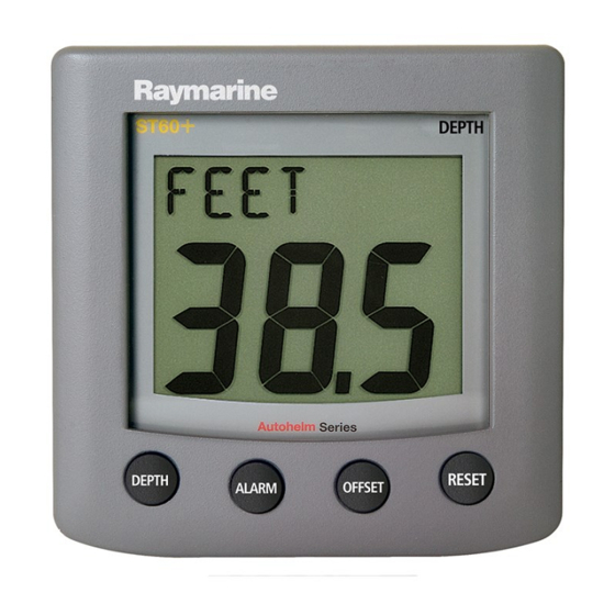
Screen layout D4424-2 1.2 Normal operation Use the flow charts in this Chapter to operate your ST60 Tridata instrument. Flow charts are provided for: • Using the depth key. This gives access to current depth information. On mas- ter instruments, this also gives access to depth alarm threshold information, and allows you to set the alarm thresholds. -
Page 14: Depth
81040_5.book Page 2 Monday, February 20, 2006 2:39 PM ST60 Tridata Instrument Owner’s Manual • Using the trip key to gain access to log, trip, water temperature and timer information. All key presses are momentary unless otherwise stated. Depth Using the... -
Page 15: Depth Alarm Threshold Displays
81040_5.book Page 3 Monday, February 20, 2006 2:39 PM Chapter 1: Operation Depth alarm threshold displays The alarm threshold displays are available if the instrument is operating as a master. Each display is identified by the presence of an alarm symbol ( )and either an up arrow for a shallow alarm or a down arrow for a deep alarm. -
Page 16: Maximum Speed
81040_5.book Page 4 Monday, February 20, 2006 2:39 PM ST60 Tridata Instrument Owner’s Manual Boat speed speed speed VMG to Maximum windward speed speed speed Average speed Using the speed key D4414-1 Maximum speed The screen shows the maximum speed attained since the last reset. -
Page 17: Trip
81040_5.book Page 5 Monday, February 20, 2006 2:39 PM Chapter 1: Operation Trip The trip key gives access to log, trip, water temperature and timer displays, as Using the trip key shown in the illustration. trip Water temperature Trip trip trip Count-up timer... -
Page 18: Water Temperature
81040_5.book Page 6 Monday, February 20, 2006 2:39 PM ST60 Tridata Instrument Owner’s Manual The trip value is reset automatically at power-up, and if the instrument is operating as a master, the trip value can also be reset manually by pressing the reset key for 3 seconds. -
Page 19: Alarms
81040_5.book Page 7 Monday, February 20, 2006 2:39 PM Chapter 1: Operation Note: After a race-start timer has counted-down to zero, it will then start counting up. 1.3 Alarms An alarm condition occurs if: • The depth is less than the SHALLOW or SHALLOW anchor threshold. •... -
Page 20: Remote Control
ST60 Tridata Instrument Owner’s Manual 1.5 Remote control When it is connected to SeaTalk, the ST60 Tridata instrument can be controlled remotely with a SeaTalk Remote Keypad Unit. Remote control of an instrument is indicated by a REMOTE legend on the display, to indicate that the keypad has control. -
Page 21: Chapter 2: Maintenance And Faultfinding
Chapter 2: Maintenance and Faultfinding 2.1 Maintenance Servicing and safety • Raymarine equipment should be serviced only by authorised Raymarine ser- vice technicians. They will ensure that servicing procedures and replacement parts used will not affect performance. There are no user-serviceable parts in any Raymarine product. -
Page 22: Cabling
) are still being met before further investigating the problem. Fixing faults All Raymarine products are subjected to comprehensive test and quality assurance programmes prior to packing and shipping. However, if a fault occurs, the following table may help to identify and rectify the problem. -
Page 23: Technical Support
Please visit the Customer Support area of our web site at: www.raymarine.com As well as providing a comprehensive Frequently Asked Questions section and servicing information, it also gives e-mail access to the Raymarine Technical Support Department and a details of the locations of Raymarine agents, worldwide. - Page 24 81040_5.book Page 12 Monday, February 20, 2006 2:39 PM ST60 Tridata Instrument Owner’s Manual The Software issue number can be found by using the Calibration facility, see Chapter 4, Calibration...
-
Page 25: Installation
Chapter 3: Installation Chapter 3: Installation This chapter describes how to install the ST60 Tridata instrument, and associated Speed and Depth transducers. The transducers are fitted in the hull of the vessel and connected to the rear of the instrument. The actual type of transducers depends on the type of hull in which they are to be installed. - Page 26 81040_5.book Page 14 Monday, February 20, 2006 2:39 PM ST60 Tridata Instrument Owner’s Manual Hull material Speed transducer Depth transducer Glass reinforced M78712 Through hull plastic M78713 Through hull plastic or plastic (GRP) M78718 Retractable through hull Steel M78712 Through hull plastic M78713 Through hull plastic or...
-
Page 27: Instrument
81040_5.book Page 15 Monday, February 20, 2006 2:39 PM Chapter 3: Installation • Be at least 150 mm (6 in) away from the keel (ideally ahead of the keel if a sail- ing yacht). • Be as near as possible to the centre line of the vessel. •... -
Page 28: Emc Installation Guidelines
ST60 instrument dimensions D5785-1 EMC Installation Guidelines All Raymarine equipment and accessories are designed to the best industry standards for use in the recreational marine environment. Their design and manufacture conforms to the appropriate Electromagnetic Compatibility (EMC) standards, but correct installation is required to ensure that performance is not compromised. -
Page 29: Suppression Ferrites
Raymarine equipment. Always use the ferrites supplied by Raymarine. D3548-2 Connections to Other Equipment If your Raymarine equipment is to be connected to other equipment using a cable not supplied by Raymarine, a suppression ferrite MUST always be attached to the cable near the Raymarine unit. -
Page 30: Procedures
If you have ordered the flush mounting option a low-profile bezel and four fixing screws are also provided. Fitting the instrument The ST60 Tridata instrument can be installed using one of a number of different mounting options: • Surface mounting. Gives a profile of approximately 24 mm. -
Page 31: Flush Mounting
81040_5.book Page 19 Monday, February 20, 2006 2:39 PM Chapter 3: Installation Surface mounting D4343-2 2. Apply the surface mount template (supplied at the rear of this handbook) to the selected location and mark the centres for the fixing studs (1) and the aperture (3) that will take the rear casing of the instrument. - Page 32 81040_5.book Page 20 Monday, February 20, 2006 2:39 PM ST60 Tridata Instrument Owner’s Manual Fitting the low-profile bezel In order to flush-mount your ST60 instrument, you must first replace the standard bezel with the low-profile bezel as follows: 1. Hold the instrument in both hands with the display towards you.
- Page 33 81040_5.book Page 21 Monday, February 20, 2006 2:39 PM Chapter 3: Installation Fitting the low profile bezel D4362-2 Flush mounting procedure Flush mounting Flush mount your instrument (see the illustration) as follows: Fit- 1. Assemble the ST60 instrument and low-profile bezel as described under ting the low-profile bezel 2.
-
Page 34: Bracket Mounting
To bracket mount your ST60 instrument, do so in accordance with the Control Unit Instruction Sheet Mounting Bracket Fitting transducer The ST60 Tridata instrument is supplied, with appropriate through-hull Speed and Depth transducers. -
Page 35: Running Transducer Cable
Each transducer type has a 14 m (45 ft) cable fitted with spade terminals for connection to the ST60 Tridata instrument. The manner in which you run the cable will depend on the locations of the transducers and instrument. The following guidelines are provided: •... -
Page 36: Connecting The Instrument
Where a SeaTalk system includes an autopilot, the power for the system is provided by the autopilot. A range of Raymarine SeaTalk extension cables is available to connect separated instruments. These cables are supplied with a SeaTalk connector fitted to each end. -
Page 37: Power Supply Connections
81040_5.book Page 25 Monday, February 20, 2006 2:39 PM Chapter 3: Installation Power supply connections SeaTalk systems CAUTION: When instruments are connected to SeaTalk, ensure that the power supply for the SeaTalk 12 V line is protected by a 5 A fuse. Systems with a large number of instruments on the SeaTalk bus may require connections to the power supply from each end of the system (‘ring-main’... - Page 38 81040_5.book Page 26 Monday, February 20, 2006 2:39 PM ST60 Tridata Instrument Owner’s Manual To fit a power cable: 1. Ensure the intended power source is switched off. If you are using a 12 V bat- tery, ensure the power cable is not connected to the battery.
-
Page 39: Calibration
Chapter 4: Calibration 4.1 Introduction The ST60 Tridata instrument is set up with factory-programmed default settings, so in order to optimise the performance of the instrument on board a particular vessel, the procedures in this Chapter must be carried out immediately after the completion of installation and before the equipment is used for navigational purposes. - Page 40 • Set timer alarm buzzer on or off. Separate routines are provided for the User calibration of the depth and speed functions. To carry out either of these routines: 1. Power up the ST60 Tridata instrument. To start User calibration hold down...
-
Page 41: Depth
81040_5.book Page 29 Monday, February 20, 2006 2:39 PM Calibration Depth units You can set either FEET or METRES. From User calibration start screen Set depth units depth depth Shallow Set depth offset alarm lock depth User calibration - depth D4417-1 Depth offset WARNING:... -
Page 42: Shallow Alarm Lock
81040_5.book Page 30 Monday, February 20, 2006 2:39 PM ST60 Tridata Instrument Owner’s Manual • If you want to display the depth reading from the transducer, set a value of 0.0. • If you want to apply a water line offset, adjust the displayed reading until the appropriate positive offset value is shown. -
Page 43: Set Speed Units
81040_5.book Page 31 Monday, February 20, 2006 2:39 PM Calibration Set speed units Select either KTS (knots), MPH (miles per hour) or KMH (kilometres per hour), as required. Set speed resolution Select resolution of either 0.01 or 0.1 as required. Set log units Select either NM (nautical miles), SM (statute miles) or KM (kilometres), as required. - Page 44 81040_5.book Page 32 Monday, February 20, 2006 2:39 PM ST60 Tridata Instrument Owner’s Manual From User calibration start screen Set speed Set timer alarm units speed speed Temperature calibration speed Set speed resolution speed Set temperature speed units Set log...
-
Page 45: Adjust To Sog
81040_5.book Page 33 Monday, February 20, 2006 2:39 PM Calibration Adjust to SOG The Adjust to SOG screen is displayed only if SOG data is available from SeaTalk. The current SOG is displayed in the bottom section of the display (SG12.8 in the illustration), and the current speed registered by the instrument, as large figures in the middle section of the display (12.3 in the illustration). -
Page 46: Intermediate Calibration
81040_5.book Page 34 Monday, February 20, 2006 2:39 PM ST60 Tridata Instrument Owner’s Manual 4.3 Intermediate calibration Intermediate calibration enables you to: • Check the instrument software version. • Check the instrument status - either YES (master)) or NO (repeater). You can also change the depth status, as required. -
Page 47: Speed Calibration
81040_5.book Page 35 Monday, February 20, 2006 2:39 PM Calibration depth speed Software version depth Instrument status (or NO for repeater) (or NO for repeater) depth Carry out speed calibration as detailed in Speed calibration - sheets 1 & 2 depth Intermediate calibration D4419-1... - Page 48 81040_5.book Page 36 Monday, February 20, 2006 2:39 PM ST60 Tridata Instrument Owner’s Manual Note: It is recommended that the speed calibration procedure is carried out in conditions of minimum tidal drift. To carry out a speed calibration, start the Intermediate calibration procedure and use the speed key to proceed to the Calibration run length screen (see sheet 1 of the Speed calibration flow chart).
- Page 49 81040_5.book Page 37 Monday, February 20, 2006 2:39 PM Calibration from Intermediate calibration (Instrument status display) either Calibration run length trip reset to set length of calibration run trip reset trip reset At the start of the outward cal run press Carry out the outward leg of...
- Page 50 81040_5.book Page 38 Monday, February 20, 2006 2:39 PM ST60 Tridata Instrument Owner’s Manual At the start of the outward cal run press Carry out the from Speed outward leg of calibration - sheet 1 speed the second cal run...
-
Page 51: Leaving Intermediate Calibration
81040_5.book Page 39 Monday, February 20, 2006 2:39 PM Calibration Leaving Intermediate calibration Hold down the depth and speed keys for 2 seconds, to save your settings, exit Intermediate calibration and resume normal operation. 4.4 Dealer calibration The Dealer calibration procedures enable the following parameters to be set: •... - Page 52 81040_5.book Page 40 Monday, February 20, 2006 2:39 PM ST60 Tridata Instrument Owner’s Manual Hold down depth speed for approximately 12 seconds trip reset Calibration on/off depth depth Speed Factory response defaults At each screen use either trip reset to set the required values...
-
Page 53: Boat Show Mode
81040_5.book Page 41 Monday, February 20, 2006 2:39 PM Calibration Boat show mode CAUTION: Do NOT enable this mode. It must only be used for demonstration purposes. Ensure that the Boatshow Mode Use is set to OFF. If necessary, use the trip or reset key to achieve this. - Page 54 81040_5.book Page 42 Monday, February 20, 2006 2:39 PM ST60 Tridata Instrument Owner’s Manual...
- Page 55 81040_5.book Page 1 Monday, February 20, 2006 2:39 PM Drill 5mm (3/16in) diameter ST60 Surface Mount Template Machine hole 90mm (3.54in) diameter Shaded areas to be removed Drill 5mm (3/16in) diameter D4436-1...
- Page 56 81040_5.book Page 2 Monday, February 20, 2006 2:39 PM...
- Page 57 81040_5.book Page 3 Monday, February 20, 2006 2:39 PM ST60 Flush Mount Template 4 holes 6 mm diameter Shaded area to be removed 109 mm D4437-1...
- Page 58 81040_5.book Page 4 Monday, February 20, 2006 2:39 PM...
- Page 59 For any Raymarine product or system that (i) has been installed on your vessel by a Raymarine-certified service agent or by a Raymarine OEM, and (ii) has a MSRP equal to or greater than USD $2,500, you are eligible to receive warranty service by a Raymarine certified service agent on-board your vessel (‘On Board Warranty Service’) for a period of 12...
- Page 60 Other conditions This Warranty is fully transferable provided that you furnish the original proof of purchase to Raymarine or, in the case of On Board Warranty Service, to a Raymarine-certified service agent. This Warranty is void if the label bearing the serial number has been removed or defaced.
- Page 61 2 years (24 months), subject to the limits contained in this warranty document. In the case of a product installed, by a Raymarine certified OEM installer, on a new boat prior to the sale of the boat to a customer, the 2-year period will begin on the date of the sale of the boat to the customer.
- Page 62 Raymarine Service Agent) at no further cost and promptly returned to the customer. 3.3 In cases where the customer is making a warranty claim and the product has been installed by a Raymarine certified installer, (boat builder, installer, dealer etc.) i.e. Onboard warranty, the nearest Raymarine approved service agent should be contacted and onboard service requested (which will be subject to the limits referred to in paragraph 4.12 below).
- Page 63 81040_5.book Page V Monday, February 20, 2006 2:39 PM Raymarine World Wide Warranty 4.10 If repairs are necessary under the warranty, the affected product must be forwarded to a Raymarine facility or a Raymarine approved service agent, at the owner’s expense.
- Page 64 Raymarine Technical Support Raymarine Technical Support +44 (0) 23 9271 4713 1-800-539-5539 or, +1 603-881-5200 Product Repair and Service Product Repair and Service Raymarine Product Repair Center Raymarine plc Anchorage Park 21 Manchester Street, Portsmouth Merrimack, PO3 5TD NH 03054-4801...
Need help?
Do you have a question about the ST60 Tridata Instrument and is the answer not in the manual?
Questions and answers