Raymarine ST60 Commissioning Manual
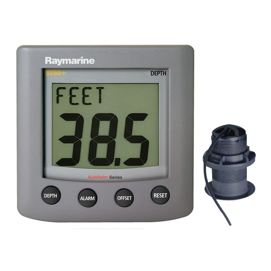
Graphic display
Hide thumbs
Also See for ST60:
- User manual ,
- Owner's handbook manual (64 pages) ,
- Operating manual (38 pages)

Related Manuals for Raymarine ST60


Summary of Contents for Raymarine ST60
- Page 1 ST60 Graphic Display Commissioning Guide Document number: 81228-1 Date: 1 January 2004...
- Page 2 Raymarine, ST60 and SeaTalk are trademarks of Raymarine Limited © Handbook contents copyright Raymarine Limited 2004...
-
Page 3: Important Information
Important information About the documentation Welcome to the Raymarine ST60 Graphic Display. The documentation for your ST60 Graphic Display is arranged so that you can install, commission and quickly use your Display, keeping to hand only the information necessary. •... -
Page 4: Emc Installation Guidelines
CAUTION: Setup requirement The ST60 Graphic Display is calibrated to factory (default) settings when first supplied. To ensure optimum performance on your boat, this product must be setup before use. Do NOT use the product until it has been setup using the procedures in Chapter 2, Preparation for Use. -
Page 5: Suppression Ferrites
Raymarine equipment. Always use the ferrites supplied by Raymarine. Connections to Other Equipment If your Raymarine equipment is to be connected to other equipment using a cable not supplied by Raymarine, a suppression ferrite MUST always be attached to the cable near the Raymarine unit. - Page 6 ST60 Graphic Display Commissioning Guide...
-
Page 7: Table Of Contents
Contents Important information ...i About the documentation ... i Safety notices ... i EMC Installation Guidelines ... ii Suppression Ferrites ...iii Connections to Other Equipment ...iii Product information ...iii Chapter 1: System Connections ...1 1.1 Overview ... 1 Mandatory connections ... 1 Optional connections ... - Page 8 ST60 Graphic Display Commissioning Guide...
-
Page 9: Chapter 1: System Connections
ST60 Graphic Display Installation Guide. Mandatory connections The ST60 Graphic Display receives both data and power from SeaTalk. You must therefore connect at least one SeaTalk cable from the ST60 Graphic Display to SeaTalk as described below. -
Page 10: Connection Procedure
12 V dc supply (typically provided by autopilot) SeaTalk power connections Connection procedure To connect your ST60 Graphic Display: 1. Ensure that: • Power to the existing SeaTalk system is switched off. • The conditions described under Power requirements are fulfilled. -
Page 11: Using The Nmea In And Out Connectors
If you want to connect your NMEA IN and NMEA OUT connectors to an NMEA device: • Terminate each cable in an appropriate manner for connection to the device. • Ensure a ferrite is fitted to each cable, adjacent to the ST60 Graphic Dis- play. ST60 Graphic Display D6544-1... -
Page 12: What Nmea Data Is Supported
Water speed and heading NMEA to SeaTalk When certain NMEA data is available at the NMEA IN connector, it is decoded and displayed by the ST60 Graphic Display. The supported NMEA input data is detailed in the following table. Data XTE, Waypoint identifier, Bearing &... -
Page 13: Alternative Uses Of Nmea Out Connector
Auxiliary Alarm Buzzer Defining the NMEA OUT connector function Before the ST60 Graphic Display is used, you must use the procedures in Chapter 2, Initial Setup to define how the NMEA OUT connector is connected (i.e. for either NMEA out data or Auxiliary Alarm). - Page 14 ST60 Graphic Display Commissioning Guide...
-
Page 15: Chapter 2: Preparation For Use
Chapter 2: Preparation for Use 2.1 Introduction Use this chapter to set up and check the ST60 Graphic Display, before it is used operationally. Instructions are given to enable you to: Define the function of the NMEA OUT connector (see Chapter 1, System •... -
Page 16: Other User Calibration Functions
5. When you have set NMEA OUT and ALARM DRIVE as required, hold down operation. Other User calibration functions Comprehensive User calibration instructions are given in the ST60 Graphic Display Operation Guide. You can: • Set the Favorite page rollover period, or switch the rollover off. -
Page 17: Dealer Calibration
Chapter 2: Preparation for Use • Set the instrument time to local time. • Select the units in which temperature, speed, trip, depth and wind speed from NMEA, are displayed. Select the function of the display NMEA OUT connector. This is either •... -
Page 18: User Calibration On/Off
Use the (decrement) and reset (increment) buttons to set the required value. ST60 Graphic Display Commissioning Guide Response Battery voltage track... -
Page 19: Battery Voltage
1. With the BATTERY screen displayed, measure the 12 V supply voltage at the battery. 2. At the ST60 Graphic Display, use the track or reset button to set the dis- played voltage to the same value as the measured voltage. -
Page 20: Self Test
NO. Note: If YES is selected, you could inadvertently initiate a self test routine. This will not harm the product but will interrupt operation, so it is therefore NOT recommended. ST60 Graphic Display Commissioning Guide Factory default Feet Knots... -
Page 21: Leaving Dealer Calibration
ST60 Graphic Display Operation Guide. When doing this, be aware that some data types may not be supported by your system and therefore will not be displayed on your ST60 Graphic Display. If you think that data is missing, ensure that your system supports this data before assuming that a fault exists. - Page 22 ST60 Graphic Display Commissioning Guide...
-
Page 23: Index
Index Index Auxiliary Alarm connections 5 Checking operation 13 Connections Auxiliary Alarm 5 mandatory 1 NMEA 3 optional 1 procedure 2 SeaTalk 1 Dealer calibration default reset 11 enable/disable User cal 10 setting responses 10 setting voltage reading 11 Default settings 11 EMC conformance 7 Factory defaults 11 Initial checks 13... - Page 24 Index...
Need help?
Do you have a question about the ST60 and is the answer not in the manual?
Questions and answers