Raymarine ST60 Owner's Handbook Manual
Steering compass instrument
Hide thumbs
Also See for ST60:
- User manual ,
- Owner's handbook manual (64 pages) ,
- Operating manual (38 pages)

Related Manuals for Raymarine ST60


Summary of Contents for Raymarine ST60
- Page 1 ST60 Steering Compass Instrument Owner’s Handbook Document number: 81107-3 Date:1st April 2001...
- Page 2 © Copyright Raymarine Limited 2001...
-
Page 3: Table Of Contents
Introduction Contents Introduction ................v EMC conformance ............vi Data inputs ............... vi SeaTalk ............... vi Stand alone operation ..........vi Remote control ..............vii Mounting options ............vii Parts supplied ..............viii Chapter 1: Operation ............. 1 1.1 Getting started ............. 1 Calibration requirement .......... - Page 4 ST60 Steering Compass Instrument Owner’s Handbook Chapter 2: Maintenance and Fault Finding ......9 2.1 Maintenance ..............9 Servicing and safety ............ 9 Instrument ..............9 Transducer ..............9 Cabling ................ 9 2.2 Fault finding .............. 10 Preliminary procedures ..........10 Fault location .............
- Page 5 Introduction Connecting the instrument ........21 Introduction ............21 Signal connections ..........21 Power supply connections ........22 SeaTalk systems ..........22 Stand alone instruments ......... 23 Chapter 4: Calibration ............25 4.1 Introduction .............. 25 EMC conformance ............ 25 4.2 User calibration ............
- Page 6 ST60 Steering Compass Instrument Owner’s Handbook...
-
Page 7: Introduction
Thank you for purchasing a Raymarine product. We are sure your ST60 instrument will give you many years of trouble-free operation. This handbook describes how to install and use the Raymarine ST60 Steering Compass instrument. This instrument gives: • True/Magnetic Course Heading. -
Page 8: Emc Conformance
Their design and manufacture conforms to the appropriate Electromagnetic Compatibility (EMC) standards, but correct installation is required to ensure that performance is not compromised. Data inputs The ST60 Steering Compass receives data either from an associated Flux Gate Compass transducer and/or from a SeaTalk instrumentation system. SeaTalk SeaTalk enables a number of compatible instruments to be interconnected and operate as a single, integrated navigational system. -
Page 9: Remote Control
ST60 range of equipment. Mounting options If you do not want to surface mount your ST60 instrument, options are available for: • Flush mounting. If you have ordered the flush mounting option a low-profile bezel and four fixing screws are also provided. -
Page 10: Parts Supplied
Spare spade terminals are also provided, to re-terminate the transducer cable if it has to be cut to facilitate installation. Note: The above packing list is for an ST60 Steering Compass system. Where an instrument is purchased separately, the Fluxgate Compass... - Page 11 Introduction COMPASS ST60 Steering Worldwide Compass Distributors Instrument Owner's Handbook D4444-2...
- Page 12 ST60 Steering Compass Instrument Owner’s Handbook...
-
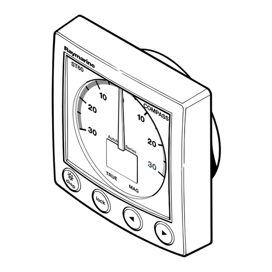
Page 13: Chapter 1: Operation
Course Over Ground (COG) can be calculated and used to provide a true course display. Calibration requirement The ST60 Steering Compass instrument is calibrated to factory (default) settings when first installed and must therefore be calibrated before use, in accordance with the procedures in Chapter 4, Calibration, to ensure optimum performance on your vessel. -
Page 14: Pointer
Sea Talk autopilot operating in Auto, Vane or Track mode, the ST60 Steering Compass is forced to operate in Auto mode. In Auto mode the ST60 Steering Compass acts as a slave display to the autopilot, with the autopilot’s locked heading displayed on the ST60 Steering Compass digital display and the analogue pointer showing the autopilot course error. -
Page 15: Unlocked Mode
Course over ground (COG) Press the disp key to select COG. Provided you have GPS or similar positioning data on the SeaTalk system, the ST60 Steering Compass displays your course over the ground. If such data is not available the digital display shows “---”. -
Page 16: Locked Mode
ST60 Steering Compass Instrument Owner’s Handbook Switch on Normal display TRUE disp disp Note: Modes marked * rely on external data. Press Course Over Average Ground* (COG) heading* for 3 seconds to reset average TRUE TRUE disp Using the disp key... -
Page 17: Operation
Chapter 1: Operation Operation To enter locked mode (see the Locked mode operation illustration), press the lock key. The current heading is applied as the locked heading and flashes for 5 seconds, after which time the heading display shows either the locked heading or the current heading, depending on what has been set up during User calibration, as the normal display in locked mode (see Chapter 4, Calibration). -
Page 18: Auto Mode
Whenever the autopilot is engaged, the heading set by the autopilot is displayed on the digital display and the analogue pointer displays the autopilot’s course error. Note: In Auto mode, all ST60 Steering Compass key functions, except illumination, are disabled. 1.3 Display illumination When the instrument is first powered up, the display illumination is set to its lowest (courtesy) level, to facilitate access to the keys. -
Page 19: Remote Control
Man overboard/reciprocal course If the vessel is turned through 110° or more when the ST60 Steering Compass is in lock mode, the ST60 Steering Compass automatically locks to the reciprocal of the original course (180° from the original). - Page 20 ST60 Steering Compass Instrument Owner’s Handbook...
-
Page 21: Chapter 2: Maintenance And Fault Finding
This will not harm the instrument and can be cleared by increasing the illumination setting to Level 3. Periodically clean your ST60 instrument with a soft damp cloth. Do NOT use chemical and/or abrasive materials to clean the instrument. -
Page 22: Fault Finding
All Raymarine products are subjected to comprehensive test and quality assurance programmes prior to packing and shipping. If a fault arises with the ST60 Steering Compass instrument, the following table may help to identify the probable cause and provide the most likely cure. -
Page 23: Chapter 3: Installation
Chapter 3: Installation Chapter 3: Installation This chapter describes how to install the ST60 Steering Compass instrument and associated Fluxgate Compass transducer. The transducer cable is connected to the rear of the instrument. For advice, or further information regarding the installation of these products, please contact the Raymarine Product Support Department or your own National Distributor. -
Page 24: Instrument
ST60 instruments can be fitted either above or below deck, provided the rear of the instrument is sited where it is protected from contact with water. -
Page 25: Emc Guidelines
To minimise the risk of operating problems: • All Raymarine equipment and cables connected to it should be: • At least 1 m (3 feet) from any equipment transmitting or cables carrying radio signals, e.g. VHF radios, cables and antennas. In the case of SSB radios, the distance should be increased to 2 m (7 ft). -
Page 26: Suppression Ferrites
If your Raymarine equipment is going to be connected to other equipment using a cable not supplied by Raymarine, a suppression ferrite MUST always be fitted to the cable close to the Raymarine unit. 3.2 Procedures As it is not possible to describe procedures for all possible installation... -
Page 27: Unpacking
Fitting the instrument The ST60 Steering Compass instrument can be installed using one of a number of different mounting options: • Surface Mounting. Gives a profile of approximately 24 mm. -
Page 28: Flush Mounting
Fitting the low-profile bezel Fitting the low-profile bezel Fitting the low-profile bezel In order to flush-mount your ST60 instrument, replace the standard bezel with the low-profile bezel as follows: 1. Hold the instrument in both hands with the display towards you. - Page 29 Chapter 3: Installation D4537-2 3. Referring to the Fitting the low-profile bezel illustration, place the instrument face upwards on a flat surface and place the rubber keypad (7) in position around the display window (i.e. so that each key outline is located over its associated key on the instrument). 4.
-
Page 30: Flush Mounting Procedure
Flush mounting procedure Flush mount your instrument (see the Flush mounting illustration) as follows: 1. Assemble the ST60 instrument and low-profile bezel as described under Fitting the low-profile bezel. 2. Ensure that: • The panel on which you intend to mount the instrument is between 3 mm and 20 mm thick. -
Page 31: Bracket Mounting
Fluxgate Compass transducer. Note: If the ST60 Steering Compass is to form part of a system which includes a SeaTalk autopilot, the ST60 Steering Compass instrument does not need its associated Fluxgate Compass transducer to operate as a slave to the autopilot. -
Page 32: Running Transducer Cable
ST60 Steering Compass Instrument Owner’s Handbook 76mm (3in) 76mm (3in) D729-3 If you are not sure of the magnetic suitability of the chosen location, carry out a survey of the site as follows: 1. Temporarily fix a simple hand bearing compass at the intended location. -
Page 33: Connecting The Instrument
Preparing wire for connection D4467-2 Connecting the instrument Introduction The ST60 Steering Compass instrument can be connected to SeaTalk as a repeater instrument. The ST60 Steering Compass instrument can also be connected: • As a stand-alone instrument connected directly to the Fluxgate Compass transducer. -
Page 34: Power Supply Connections
ST60 Steering Compass Instrument Owner’s Handbook SeaTalk cable SeaTalk cable Screen Blue Green Yellow Cable from Fluxgate Compass transducer Connections to ST60 Steering Compass instrument D4390-1 Power supply connections SeaTalk systems SeaTalk systems SeaTalk systems SeaTalk systems SeaTalk systems CAUTION When instruments are connected to SeaTalk, ensure that the power supply for the SeaTalk 12 V line is protected by a 5 A fuse. -
Page 35: Stand Alone Instruments
Chapter 3: Installation 5 A fused, 12 V dc supply (typically provided by autopilot) Screen Instruments 5 to 16 Screen SeaTalk power connections D4311-1 Stand alone instruments Stand-alone instruments are not connected to SeaTalk and therefore need to be connected to an alternative 12 V power source. Power cables are available in 2 m and 9 m lengths. - Page 36 ST60 Steering Compass Instrument Owner’s Handbook...
-
Page 37: Chapter 4: Calibration
Chapter 4: Calibration Chapter 4: Calibration 4.1 Introduction The ST60 Steering Compass instrument is set up with factory- programmed default settings, so in order to optimise the performance of the instrument on board a particular vessel, the procedures in this... -
Page 38: Linearisation
Carry out heading alignment as follows: 1. Align the vessel with a known bearing; preferably a transit bearing. 2. Use the < and > keys to adjust the value on the ST60 Steering Compass digital display until it corresponds to the known bearing. Lock mode The locked mode screen enables you to select which heading is selected as the normal operating display in locked mode. -
Page 39: Variation Setting
Chapter 4: Calibration Use the < and > keys as necessary, to select the required heading. Select: • F for Fixed heading. • C for Current heading. Hold down lock for approximately 2 seconds disp Calibration Entry Screen disp disp TRUE True/Magnetic Linearisation... -
Page 40: True/Magnetic Selection
ST60 Steering Compass Instrument Owner’s Handbook If the ST60 Steering Compass instrument is connected to SeaTalk and a value for variation is present on SeaTalk (e.g. from an autopilot), this is accepted as the value for the instrument. If a value is not present on SeaTalk, or if the instrument is not connected to SeaTalk, use the <... -
Page 41: Leaving Intermediate Calibration
Chapter 4: Calibration The display shows either: • r0 to indicate a master instrument, i.e. connected to a transducer • r1 to indicate a repeater instrument, i.e. using data from SeaTalk. Hold down for approximately 4 seconds lock disp Software version number TRUE disp... -
Page 42: Calibration On/Off
ST60 Steering Compass Instrument Owner’s Handbook Dealer calibration also gives access to the Factory defaults screen. This enables you to re-apply the factory settings if you want to reset the instrument to a known operating condition. To commence Dealer calibration, hold down the disp and lock keys together for approximately 12 seconds to select the Dealer calibration entry screen (see Dealer calibration flow chart). -
Page 43: Factory Defaults
Chapter 4: Calibration Factory defaults You can use this screen to reset the operating parameters to the factory default values. If you want to apply the factory defaults, ensure the display shows F1, but if you want to retain the values you have set up, ensure that the display shows F0. -
Page 44: Leaving Dealer Calibration
ST60 Steering Compass Instrument Owner’s Handbook Leaving Dealer calibration Hold down the disp and lock keys for 2 seconds, to save your changes, exit Dealer calibration and resume normal operation. - Page 45 Drill 5mm (3/16in) diameter ST60 Surface Mount Template Machine hole 90mm (3.54in) diameter Shaded areas to be removed Drill 5mm (3/16in) diameter D4436-1...
- Page 47 ST60 Flush Mount Template 4 holes 6 mm diameter Shaded area to be removed 109 mm D4437-1...
- Page 49 During this period, except for certain products, travel costs (auto mileage and tolls) up to 100 round trip highway miles (160 kilometres) and travel time of 2 hours, will be assumed by Raymarine only on products where proof of installation or commission by authorized service agents, can be shown.
- Page 50 Factory Service Centers United States of America UK, Europe, Middle East, Far East Raymarine Inc Raymarine Ltd 22 Cotton Road, Unit D Anchorage Park, Portsmouth Nashua, NH 03063-4219, USA PO3 5TD, England Telephone: +1 603 881 5200 Telephone: +44 (0)23 9269 3611...
Need help?
Do you have a question about the ST60 and is the answer not in the manual?
Questions and answers