Sign In
Upload
Manuals
Brands
Beckhoff Manuals
Recording Equipment
EM7004
Beckhoff EM7004 Manuals
Manuals and User Guides for Beckhoff EM7004. We have
1
Beckhoff EM7004 manual available for free PDF download: Documentation
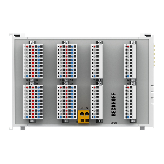
Beckhoff EM7004 Documentation (130 pages)
4 Axis Interface, 16 Digital Inputs, 16 Digital Outputs, 4 Analog Outputs, 4 Encoder Inputs
Brand:
Beckhoff
| Category:
Recording Equipment
| Size: 5.23 MB
Table of Contents
Table of Contents
3
1 Foreword
4
Notes on the Documentation
4
Safety Instructions
5
Documentation Issue Status
6
Version Identification of Ethercat Devices
6
Fig. 1 EL5021 el Terminal, Standard IP20 IO Device with Batch Number and Revision ID (Since 2014/01)
8
Fig. 2 EK1100 Ethercat Coupler, Standard IP20 IO Device with Batch Number
8
Fig. 3 CU2016 Switch with Batch Number
8
Fig. 4 EL3202-0020 with Batch Numbers 26131006 and Unique ID-Number 204418
9
Fig. 5 EP1258-00001 IP67 Ethercat Box with Batch Number 22090101 and Unique Serial Number 158102
9
Fig. 6 EP1908-0002 IP76 Ethercat Safety Box with Batch Number 071201FF and Unique Serial Number 00346070
9
Fig. 7 EL2904 IP20 Safety Terminal with Batch Number/Date Code 50110302 and Unique Serial Num- Ber 00331701
9
2 Product Overview
10
Terminal Modules - System Overview
10
Fig. 8 Terminal Modules - System Overview
10
Fig. 9 Terminal Modules - Pluggable Connection
10
Fig. 10 Terminal Module with Plug Connector for Single Conductor Connection Method (ZS2001-0002)
11
Fig. 11 Terminal Module with Connector for Three-Wire Connection (ZS2001-0004)
11
Fig. 12 Terminal Module with 16 Channels
12
Fig. 13 Terminal Module with 32 Channels
12
Fig. 14 Terminal Module with 64 Channels
12
Introduction
13
Fig. 15 EM7004
13
Technical Data
14
Basic Function Principles
14
Analog Process Data
15
Process Data Equations
15
3 Mounting and Wiring
19
Recommended Mounting Rails
19
Dimensions
19
Mounting and Demounting - Terminals with Traction Lever Unlocking
19
Fig. 16 EM7004 Dimensions
19
Installation Positions
21
Fig. 17 Recommended Distances for Standard Installation Position
22
Fig. 18 Other Installation Positions
23
Wiring
24
Fig. 19 Clamped Joint for Power Supply
24
Fig. 20 Connection of the Module with Alternative Power Supply
25
Connection Technology
28
Fig. 21 Input Circuits Single-, Two- and Three-Conductor Mode
28
Fig. 22 Output Circuits Single-, Two- and Three-Conductor Mode
29
4 Commissioning
30
Twincat Quick Start
30
Fig. 23 Relationship between User Side (Commissioning) and Installation
31
Fig. 24 Control Configuration with an Embedded PC and Input (EL1004) and Output (EL2008)
32
Fig. 25 Initial Twincat 2 User Interface
32
Fig. 26 Selection of the Target System
33
Fig. 27 Specify the PLC for Access by the Twincat System Manager: Selection of the Target System
33
Fig. 28 Select "Scan Devices
34
Fig. 29 Automatic Detection of I/O Devices: Selection the Devices to be Integrated
34
Fig. 30 Mapping of the Configuration in the Twincat 2 System Manager
35
Fig. 31 Reading of Individual Terminals Connected to a Device
35
Fig. 32 Twincat PLC Control after Startup
36
Fig. 33 Sample Program with Variables after a Compile Process (Without Variable Integration)
37
Fig. 34 Appending the Twincat PLC Control Project
37
Fig. 35 PLC Project Integrated in the PLC Configuration of the System Manager
38
Fig. 36 Creating the Links between PLC Variables and Process Objects
38
Fig. 37 Selecting PDO of Type BOOL
39
Fig. 38 Selecting Several Pdos Simultaneously: Activate "Continuous" and "All Types
39
Fig. 39 Application of a "Goto Link" Variable, Using "Main.bel1004_Ch4" as a Sample
40
Fig. 40 Choose Target System (Remote)
41
Fig. 41 PLC Control Logged In, Ready for Program Startup
42
Twincat 2
54
Twincat 3
54
Twincat Development Environment
54
Installation of the Twincat Real-Time Driver
54
Notes Regarding ESI Device Description
60
Twincat ESI Updater
64
Distinction between Online and Offline
64
OFFLINE Configuration Creation
65
ONLINE Configuration Creation
70
Ethercat Subscriber Configuration
78
General Notes - Ethercat Slave Application
88
5 Object Description and Parameterization
96
Objects for Commissioning
97
Objects for Regular Operation
98
Standard Objects (0X1000-0X1Fff)
98
Profile-Specific Objects (0X6000-0Xffff)
107
6 Appendix
113
Ordering Information for EM7004 Modules and EM/KM Connectors
113
Ethercat al Status Codes
114
Firmware Compatibility
114
Firmware Update El/Es/Em/Epxxxx
114
Restoring the Delivery State
125
Support and Service
126
List of Illustrations
127
Advertisement
Advertisement
Related Products
Beckhoff EL5101
Beckhoff EL5101-0011
Beckhoff EL5032
Beckhoff EL500 Series
Beckhoff EL5001
Beckhoff EL5002
Beckhoff EP6002-0002
Beckhoff EP6001-0002
Beckhoff EJ5002
Beckhoff EP2918-0032
Beckhoff Categories
Touch terminals
Industrial PC
Control Unit
Touch Panel
Power Supply
More Beckhoff Manuals
Login
Sign In
OR
Sign in with Facebook
Sign in with Google
Upload manual
Upload from disk
Upload from URL