
Related Manuals for PROEL ATMP160XL


Summary of Contents for PROEL ATMP160XL
- Page 1 ATMP160XL Amplificatore Mixer 160W con Modulo Multimediale Media Player Mixer Amplifier 160W MANUALE UTENTE USER’S MANUAL...
-
Page 3: Table Of Contents
SOMMARIO PRECAUZIONI D’USO ..........................4 DESCRIZIONE .............................. 6 FUNZIONI E CONTROLLI PANNELLO FRONTALE ..................7 FUNZIONI E CONTROLLI PANNELLO POSTERIORE ................... 10 CONNESSIONI ALTOPARLANTI ......................... 13 ESEMPI DI POSSIBILI CONNESSIONI ......................14 SPECIFICHE TECNICHE ..........................15 CONTENUTO DELLA CONFEZIONE ......................15... -
Page 4: Precauzioni D'uso
1. PRECAUZIONI D’USO AVVERTENZA:Per ridurre il rischio di folgorazione, non rimuovere il coperchio (o il pannello posteriore). All’interno non sono contenute parti riparabili dall’utente; affidare la riparazione a personale qualificato. ATTENZIONE: Per ridurre il rischio d’incendio o di folgorazione, non esporre questo apparecchio alla pioggia o all’umidità. Questo simbolo, ove compare, segnala la presenza di un voltaggio pericoloso non isolato all’interno del corpo dell’apparecchio –... - Page 5 In caso si verifichino interferenze nel circuito di provenienza, il valore di THD sarà superiore al 10%. Non installare questo apparato in una libreria o in altri luoghi a spazio ristretto • PROEL S.P.A. declina ogni responsabilità in caso di scorretta installazione dell’unità.
-
Page 6: Descrizione
Grazie per aver scelto un prodotto Proel e della fiducia riposta nel nostro marchio, sinonimo di professionalità, accuratezza, elevata qualità ed affidabilità. Tutti i nostri prodotti sono conformi alle normative CE per utilizzazione continua in impianti di diffusione sonora. 2. DESCRIZIONE Amplificatore mixer professionale 160W, 70/100V, 4Ω, completo di modulo multimediale con Tuner FM, lettore MP3 su supporto... -
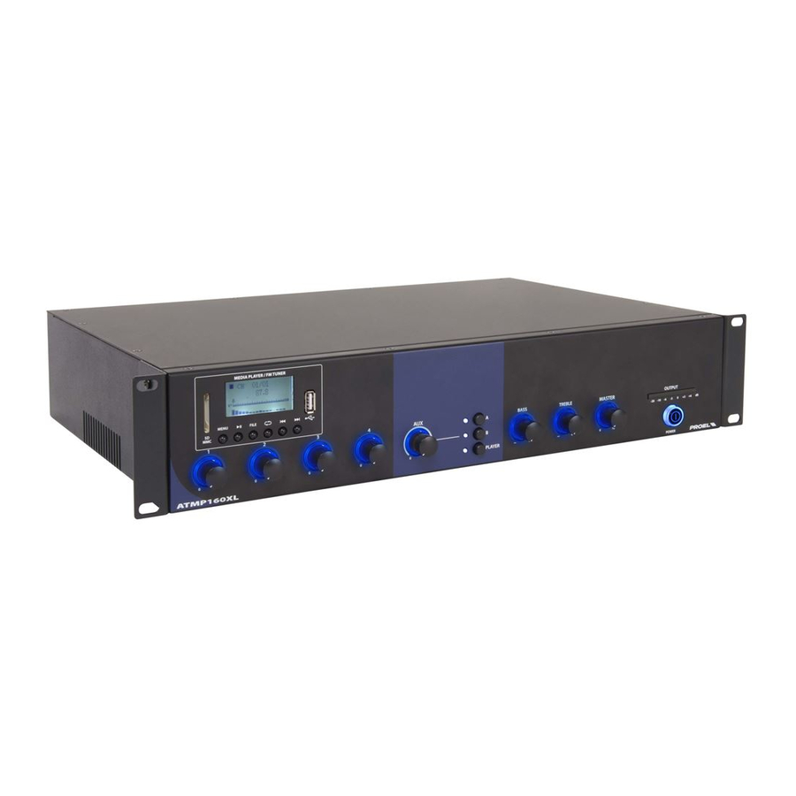
Page 7: Funzioni E Controlli Pannello Frontale
3. FUNZIONI E CONTROLLI PANNELLO FRONTALE fig.1 1. POWER Interruttore principale con indicatore luminoso di accensione. 2. MASTER Controllo di volume Master. 3. TREBLE Controllo di tono Alti Il controllo di tono TREBLE svolge un intervento di +/- 10 dB nello spettro delle frequenze degli acuti, permettendo di effettuare una corretta equalizzazione del segnale riprodotto. - Page 8 9. Modulo Multimediale con sintonizzatore radio e lettore MP3 su supporto USB / SD A Tasto MENU Con una pressione prolungata del tasto possiamo spegnere/accendere il dispositivo multimediale. Ad ogni pressione veloce del il tasto il sistema passa ciclicamente dalla modalità: SD/USB →...
- Page 9 C FILE In modalità SD/USB: Alla pressione del tasto si entra nella modalità di “Navigazione File” è possibile muoversi nella lista mediante i tasti “I<<” , “>>I”, una volta selezionata la traccia premere PLAY per la riproduzione Nota: Il tasto non è attivo nella modalità TUNER e BLUETOOT. PLAY MODE In modalità...
-
Page 10: Funzioni E Controlli Pannello Posteriore
4. FUNZIONI E CONTROLLI PANNELLO POSTERIORE fig.2 1. INGRESSO ALIMENTAZIONE DI RETE con Alloggio per il fusibile Collegare l’unità alla rete Alimentazione 230/117V~ 50/60Hz. FUSIBILE 100÷240 V~ 50/60Hz Fusibile: T2AL AC250V. 2. INPUT 1 ÷ INPUT 4 Ingresso bilanciato/sbilanciato su connettore “Euroblock”. fig.3 Gli ingressi INPUT1, INPUT2, INPUT3 e INPUT4 sono di tipo bilanciato/sbilanciato, utilizzabili per il collegamento sia di microfoni dinamici a bassa impedenza (30-600Ω), sia di microfoni a condensatore con alimentazione phantom a 48V,... - Page 11 b) Per scegliere il tipo di sorgente da connettere agire sui selettori (fig.3 rif.a): LINE per sintonizzatori AM/FM, lettori CD ecc. PH per microfoni a condensatore. MIC per microfoni dinamici. c) “contatto pulito” Ogni ingresso dispone di un “contatto pulito” che ha due funzioni “Attivazione Chime” e “Forzatura del silenziamento degli ingressi”.
- Page 12 Esempi: ON–ON–ON–ON – Vox abilitato su tutti gli ingressi ON–OFF–ON–OFF – Vox abilitato sugli ingressi 1 - 3 e disabilitato sugli ingressi 2 - 4 ………………………… OFF–OFF–OFF–OFF – Vox disabilitato su tutti gli ingressi Funzionamento del VOX Ogni ingresso INPUT 1 ÷ INPUT 4 dispone di una funzione VOX inseribile e disinseribile mediante l’apposito PIN (Vox Priority Enabling): quando il circuito VOX di uno dei canali con VOX ad ON (abilitato) rileva la presenza di un segnale audio sul rispettivo ingresso (fig.2, rif.2), i canali AUX (fig.2, rif.3) e i canali aventi il VOX a OFF (disabilitato) saranno silenziati, mentre tutti i canali con VOX a ON saranno mixati in uscita.
-
Page 13: Connessioni Altoparlanti
9. USCITA ALTOPARLANTI Il dispositivo permette il collegamento di diffusori a impedenza costante (4Ω) o diffusori a tensione costante (70V, 100V). Non è possibile collegare un mix di essi. 5. CONNESSIONI ALTOPARLANTI Attenzione Per prevenire il rischio di contatto con scariche elettriche non toccare mai le uscite dell’amplificatore quando esso è in funzione. -
Page 14: Esempi Di Possibili Connessioni
6. ESEMPI DI POSSIBILI CONNESSIONI... -
Page 15: Specifiche Tecniche
Alette rack Cavo di alimentazione di rete Manuale di utilizzo La Proel SpA persegue una politica di costante ricerca e sviluppo, di conseguenza si riserva il diritto di apportare miglioramenti ai prodotti esistenti, senza preavviso e in qualunque momento. REV.00 19/17... - Page 17 TABLE OF CONTENTS IMPORTANT SAFETY INSTRUCTIONS ....................... 18 DESCRIPTION ............................20 FRONT PANEL CONTROLS AND FUNCTIONS .................... 21 REAR PANEL FUNCTIONS AND CONTROLS ....................24 LOUDSPEAKER CONNECTION ........................27 EXAMPLES OF POSSIBLE CONNECTIONS ....................29 TECHNICAL SPECIFICATIONS ........................30 CONTENTS OF THE PACKAGE ........................30...
-
Page 18: Important Safety Instructions
1. IMPORTANT SAFETY INSTRUCTIONS CAUTION: To reduce the risk of electric shock do not remove cover (or back panel). No user serviceable parts inside. Refer servicing to qualified personnel only. WARNING: To reduce the risk of fire or electric shock, do not expose this apparatus to rain or moisture. This symbol is intended to alert the user of the presence of uninsulated dangerous voltage within the product enclosure that may be of sufficient magnitude to constitute a risk of electric shock to persons. - Page 19 In case of interference from source signal, THD value will raise over 10%. Don’t place this unit in a bookshelf or in other enclosed spaces. 27. PROEL S.P.A. is not responsible for any damage that occurs due to an incorrect installation of the unit.
-
Page 20: Description
Thank you for choosing Proel and for your trust in our brand: we strive to guarantee professionalism, accuracy, high quality and reliability to our customers. All our products comply with EC regulations on sound reinforcement devices. 2. DESCRIPTION 160W, 70/100V, 4Ω professional mixer amplifier complete with multimedia module with Tuner FM, MP3 player on SD MCC/USB support and Bluetooth connection. -
Page 21: Front Panel Controls And Functions
3. FRONT PANEL CONTROLS AND FUNCTIONS Fig. 1 1. POWER Main switch with ON light indicator. 2. MASTER Master volume control. 3. TREBLE High tone control TREBLE tone control carries out an +/- 10 dB intervention in the high frequency range, allowing a correct equalization of the reproduced signal. - Page 22 9. Multimedia Module with radio tuner and MP3 reader on USB/SD support A MENU key It is possible to turn on/off the multimedia device by pressing the key and holding it down. Each time the key is quickly pressed, the system cycles through the modes: SD/USB →...
- Page 23 “>>I” keys. Once the track is selected press PLAY for the playback. Note: The key is not active in TUNER and BLUETOOTH mode. PLAY MODE SD/USB mode: This key changes the playback mode of the audio files. A little icon on the display shows the current mode. Each time the key is quickly pressed, the system cycles through the modes: NORMAL: plays all the audio files in the memories and folders, once the last audio file plays it stops.
-
Page 24: Rear Panel Functions And Controls
4. REAR PANEL FUNCTIONS AND CONTROLS Fig. 2 1. NETWORK POWER SUPPLY INPUT with fuse housing Connect the unit to the mains Power Supply 230/117V~ 50/60Hz. FUSE 100÷240 V~ 50/60Hz Fuse: T2AL AC250V. 2. INPUT 1 ÷ INPUT 4 Balanced/unbalanced input on “Euroblock” connector. fig.3 The INPUT1, INPUT2, INPUT3 e INPUT4 inputs are of balanced/unbalanced type, used for the connection of low impedance dynamic microphones (30-600Ω), condenser microphones with 48V phantom power supply and audio... - Page 25 b) Use the selectors to choose the source type to connect (fig.3 ref.a): LINE for AM/FM tuners, CD players etc. PH for condenser microphones with +48V phantom power MIC for dynamic microphones c) “Dry Contact” Each input has a “Dry Contact” that has the functions “Chime Activation” and “Force Input Muting”. These functions can also be activated simultaneously and are subjected to the (ON –...
- Page 26 Examples: ON–ON–ON–ON – Vox enabled on all inputs ON–OFF–ON–OFF – Vox enabled on the 1 - 3 inputs and disabled on the 2 - 4 inputs ………………………… OFF–OFF–OFF–OFF – Vox disabled on all inputs VOX operation Each INPUT 1 ÷ INPUT 4 has a VOX function that can be switched on and off using the relative PIN (Vox Priority Enabling): when the VOX circuit of one of the channels with VOX ON (enabled) detects the presence of an audio signal on the relative input (fig.2, ref.2), the AUX channels (fig.2, ref.3) and the channels with VOX OFF (disabled) will be muted, while all the channels with VOX ON will be mixed in the output.
-
Page 27: Loudspeaker Connection
5. LOUDSPEAKER CONNECTION Attention To avoid the risk of electric shocks, never touch the amplifier outputs when they are operating. The device can be used with loudspeakers having constant impedance (4Ω) as well as constant voltage (70V, 100V). Keep the following instructions in mind when carrying out connections. Constant impedance line: Connect the constant impedance line (4Ω) between the “COM”... - Page 28 Constant voltage line: Connection to 100V or 70V Connect the constant voltage line (100V or 70V) between the two “COM” and “100V” (or “70V”) terminals (Fig. 2, Ref. 4) . The loudspeakers must be supplied with a transformer having an input voltage equivalent to that of the amplifier. ...
-
Page 29: Examples Of Possible Connections
6. EXAMPLES OF POSSIBLE CONNECTIONS... -
Page 30: Technical Specifications
8. CONTENTS OF THE PACKAGE Amplifier Rack adapters Network power supply cable Operating Manual Proel SpA is committed to a constant research and development policy and therefore reserves the right to change and improve its products at any time without notice. REV.00 19/17... - Page 32 PROEL S.p.A. (World Headquarters - Factory) Via alla Ruenia 37/43 64027 Sant’Omero (Te) – Italy Tel: +39 0861 81241 Fax: +39 0861 887862 www.proel.com...
Need help?
Do you have a question about the ATMP160XL and is the answer not in the manual?
Questions and answers