
Related Manuals for PROEL AUP4125S


Summary of Contents for PROEL AUP4125S
- Page 1 AUP4125S / AUP4250S Unità di Potenza a 4 Canali 4‐Channel Power Amplifier قنوات 4وحدة طاقة بـ MANUALE UTENTE INSTRUCTION MANUAL دليل المستخدم ...
- Page 2 ...
-
Page 3: Table Of Contents
INDICE PRECAUZIONI D’USO .......................... 4 DESCRIZIONE .............................. 6 FUNZIONI E CONTROLLI PANNELLO FRONTALE .................. 7 FUNZIONI E CONTROLLI PANNELLO POSTERIORE .................. 8 CONNESSIONI ALTOPARLANTI ......................... 11 ESEMPI DI POSSIBILI CONNESSIONI ...................... 13 CARATTERISTICHE TECNICHE ........................ 14 CONTENUTO DELLA CONFEZIONE ...................... 14 ... -
Page 4: Precauzioni D'uso
PRECAUZIONI D’USO AVVERTENZA:Per ridurre il rischio di folgorazione, non rimuovere il coperchio (o il pannello posteriore). All’interno non sono contenute parti riparabili dall’utente; affidare la riparazione a personale qualificato. ATTENZIONE: Per ridurre il rischio d’incendio o di folgorazione, non esporre questo apparecchio alla pioggia o all’umidità. Questo simbolo, ove compare, segnala la presenza di un voltaggio pericoloso non isolato all’interno del corpo dell’apparecchio – voltaggio sufficiente a costituire un rischio di folgorazione. Questo simbolo, ove appare, segnala, importanti istruzioni d’uso e manutenzione nel testo allegato. Leggere il manuale . ... - Page 5 • Utilizzare unicamente i connettori e gi accessori specificati dal produttore. • L’apparato deve essere collocato in un rack metallico (vedi INSTALLAZIONE) e tenuto lontano da: Luoghi umidi Esposizione diretta a fonti di calore (come luce solare). Luoghi non sufficientemente ventilati • In presenza di temporali con fulmini o quando l’apparato non è utilizzato, estrarre la spina d’alimentazione dalla presa. • Per prevenire il rischio di incendi e scosse elettriche, è necessario tenere l’apparato lontano da spruzzi e gocce. Sopra l’apparato non devono essere collocati vasi o altri oggetti contenenti liquidi. In caso si verifichino interferenze nel circuito di provenienza, il valore di THD sarà superiore al 10%. Non installare questo apparato in una libreria o in altri luoghi a spazio ristretto • PROEL S.P.A. declina ogni responsabilità in caso di scorretta installazione dell’unità. ...
-
Page 6: Descrizione
Grazie per aver scelto un prodotto Proel e della fiducia riposta nel nostro marchio, sinonimo di professionalità, accuratezza, elevata qualità ed affidabilità. Tutti i nostri prodotti sono conformi alle normative CE per utilizzazione continua in impianti di diffusione sonora. ... -
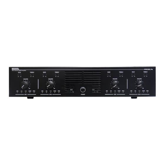
Page 7: Funzioni E Controlli Pannello Frontale
3. FUNZIONI E CONTROLLI PANNELLO FRONTALE fig.1 1. POWER Interruttore principale con indicazione luminosa di acceso 2. MASTER Controllo di volume Master del rispettivo canale 3. TREBLE and BASS Controllo di toni Alti e Bassi del rispettivo canale 4. Indicatori di stato Per ogni canale: SIG: Led Verde acceso indica la presenza di segnale in ingresso 4Ω: Led verde acceso ‐ canale impostato sul funzionamento a 4Ω Collegare al morsetto di uscita (fig.2, rif.8) carichi con impedenza minima non inferiore a 4Ω 70V: Led rosso acceso ‐ canale impostato sul funzionamento a 70V Collegare al morsetto di uscita (fig.2, rif.8) carichi a 70V 100V: Led rosso acceso ‐ canale impostato sul funzionamento a 100V Collegare al morsetto di uscita (fig.2, rif.8) carichi a 100V PRO: Led arancione acceso – canale in Protezione Nel caso il canale vada in protezione controllare che il carico in uscita sia adeguato alle caratteristiche dell’amplificatore e/o ridurre il livello del segnale in ingresso. ... -
Page 8: Funzioni E Controlli Pannello Posteriore
FUNZIONI E CONTROLLI PANNELLO POSTERIORE fig.2 1. INGRESSO ALIMENTAZIONE DI RETE con Alloggio per il fusibile Collegare l’unità alla rete 230Vac 50/60Hz (117Vac 50/60Hz per i modelli US) FUSIBILE AUP125S: 220÷240 V~ 50/60Hz Fusibile: T 6.3 AL AC 250V 110÷127 V~ 50/60Hz Fusibile: T 12 AL AC 250V AUP250S: 220÷240 V~ 50/60Hz Fusibile: T 10 AL AC 250V 110÷127 V~ 50/60Hz Fusibile: T 20 AL AC 250V 2. Ingresso Ogni canale dispone di un proprio Ingresso bilanciato a livello linea. 3. Ingresso Prioritario Ogni canale dispone di un proprio Ingresso prioritario sbilanciato a livello linea. Collegare il segnale sbilanciato tra i morsetti “+” e “simbolo di massa”. L’ingresso prioritario dispone di una funzione VOX inseribile e disinseribile mediante l’apposito PIN (fig.2, rif.7): VOX abilitato – fin quando il circuito VOX rileva la presenza di un segnale audio sull’ingresso “PRIORITY IN CH_” (fig.2, rif.3), il rispettivo ingresso “CH_ INPUT” sarà automaticamente silenziato e in uscita sarà presente solo il segnale prioritario. ... - Page 9 conseguente alternarsi del segnale “CH_ INPUT” in uscita. Nel caso di utilizzo di quest’ingresso per annunci vocali è consigliato l’impiego della base di chiamata dedicata BM100A predisposta per attivare il contatto pulito. CONNESSIONE DELLA BASE MICROFONICA PREAMPLIFICATA BM100A Collegare il terminale della BM100A alla morsettiera dell’ingresso prioritario (fig.2, rif.3) secondo lo schema riportato sul fondo della base: Il cavo blu di “BUSY” serve solo per far accendere il led di occupato quando si hanno più basi BM100A collegate in parallelo sullo stesso ingresso, collegare i cavi blu delle varie basi tra di loro e non all’amplificatore. 4. PRI VOL Controllo di guadagno per l’ingresso “PRIORITY IN CH_”. ...
-
Page 10: Connessioni Altoparlanti
(fig.1, rif.2). SELETTORE CH3&CH4 su DUAL: I canali CH3 e CH4 funzionano in maniera indipendente. I segnali presenti sugli ingressi del canale CH3 saranno presenti esclusivamente sull’uscita amplificata CH3 (fig.2, rif.8). Analogamente per CH2. Ogni canale risponderà ai propri controlli di tono (fig.1, rif.3) e volume Master (fig.1, rif.2). SELETTORE CH3&CH4 su MONO: In questa condizione su entrambe le uscite “CH3” e “CH4” (fig.2, rif.8) sarà presente lo stesso segnale audio amplificato dato dalla somma di “CH4 INPUT” e “CH3 INPUT”, gli ingressi prioritari “PRIORITY IN CH3” e “PRIORITY IN CH4”., invece, agiranno e saranno presenti solo sui rispettivi canali. Ogni canale risponderà ai propri controlli di tono (fig.1, rif.3) e volume Master (fig.1, rif.2). 7. DIP SWITCH per la selezione della priorità e impostazione del filtro di uscita DIP SWITCH 1&2: Funzione di Priorità VOX (CH_ Priority). ON ‐ funzione di priorità VOX abilitata sul rispettivo ingresso “PRIORITY IN CH_” (fig.2, rif.3). OFF ‐ funzione di priorità VOX disabilitata sul rispettivo ingresso PRIORITY IN CH_ (fig.2, rif.3). Nota: ... - Page 11 Permette la messa a terra delle parti meccaniche dell’unità qualora la presa di corrente non sia provvista del “polo di terra” Attenzione La connessione deve essere effettuata da personale qualificato. 5. CONNESSIONI ALTOPARLANTI Quanto di seguito descritto può essere riferito a ogni singolo canale. Attenzione Per prevenire il rischio di contatto con scariche elettriche non toccare mai le uscite dell’amplificatore quando esso è in funzione. Il dispositivo può essere usato sia con altoparlanti a impedenza costante (4Ω) che a tensione costante (70V, 100V). Effettuare le connessioni tenendo conto delle seguenti indicazioni. Linea ad impedenza costante Posizionare il Selettore della modalità operativa (fig.2, rif.5) sulla posizione 4Ω. Collegare la linea a impedenza costante (4Ω) tra i due terminali “+” e “‐” del morsetto (fig.2, rif.8) . Al fine di garantire il massimo rendimento, l’impedenza totale degli altoparlanti collegati alla linea, deve essere uguale all’impedenza dell’uscita dell’amplificatore. ...
- Page 12 Linea a tensione costante Posizionare il Selettore della modalità operativa (fig.2, rif.5) sulla posizione 100V. Collegare la linea a tensione costante (100V) tra i due terminali “+” e “‐” del morsetto (fig.2, rif.8) . Gli altoparlanti devono essere dotati di un trasformatore avente una tensione d’ingresso uguale a quella fornita dall’amplificatore. La somma della potenza degli altoparlanti non deve superare la massima potenza di uscita dell’amplificatore. Posizionare il Selettore della modalità operativa (fig.2, rif.5) sulla posizione 70V. Collegare la linea a tensione costante (70V) tra i due terminali “+” e “‐” del morsetto (fig.2, rif.8) . Gli altoparlanti devono essere dotati di un trasformatore avente una tensione d’ingresso uguale a quella fornita dall’amplificatore. ...
-
Page 13: Esempi Di Possibili Connessioni
ESEMPI DI POSSIBILI CONNESSIONI ... -
Page 14: Caratteristiche Tecniche
CARATTERISTICHE TECNICHE Model: AUP4125S AUP4250S Output power RMS 4 x 125W 4 x 250W 4 X balanced line 4 X balanced line Inputs 4 X Priority unbalanced line 4 X Priority unbalanced line Input Sensitivity Line: 1V/47kΩ ‐ variable gain 600Ω Line: 1V/47kΩ ‐ variable gain 600Ω 4 Master volume controls 4 Master volume controls Controls 4 treble tone controls 4 treble tone controls, 4 bass tone controls 4 bass tone controls ... - Page 15 TABLE OF CONTENTS IMPORTANT SAFETY INSTRUCTIONS ....................... 16 DESCRIPTION ............................ 18 FRONT PANEL CONTROLS AND FUNCTIONS ................... 19 REAR PANEL FUNCTIONS AND CONTROLS .................... 20 LOUDSPEAKER CONNECTION ........................ 23 CONNECTION EXAMPLE ........................... 25 TECHNICAL FEATURE .......................... 26 CONTENTS OF THE PACKAGE ........................ 26 ...
-
Page 16: Important Safety Instructions
1. IMPORTANT SAFETY INSTRUCTIONS CAUTION: To reduce the risk of electric shock do not remove cover (or back panel). No user serviceable parts inside. Refer servicing to qualified personnel only. WARNING: To reduce the risk of fire or electric shock, do not expose this apparatus to rain or moisture. This symbol is intended to alert the user of the presence of uninsulated dangerous voltage within the product enclosure that may be of sufficient magnitude to constitute a risk of electric shock to persons. ... - Page 17 For safety reasons, do not defeat the grounding connection. Grounding is for user safety. 23. Use only connectors and accessories suggested by the manufacturer. . 24. This unit should be fitted in an equipment rack (see INSTALLATION) and kept far from: Wet places Direct exposure to heat sources (like sun light) Improperly ventilated places 25. Disconnect the power cord during storms or when the unit is not in use. In order to prevent fire and reduce risk of electric shock, it is necessary to keep the unit far from dripping water. Please don’t put cups, vases or other object containing liquids over the unit. In case of interference from source signal, THD value will raise over 10%. Don’t place this unit in a bookshelf or in other enclosed spaces. 27. PROEL S.P.A. is not responsible for any damage that occurs due to a incorrect installation of the unit. ...
-
Page 18: Description
Thank you for choosing Proel and for your trust in our brand: we strive to guarantee professionalism, accuracy, high quality and reliability to our customers. All of our products comply with EC regulations on sound reinforcement devices. 2. DESCRIPTION This new series of audio power amplifiers was designed to fulfil an evolving market in the most flexible and professional manner. The new range responds to precise operating criteria, and was designed and tested to guarantee total reliability of use, also with continuous operation. Thanks to the use of power supply switching with SMPS (switch mode power supply) technology and obtaining 70/100V electronically without transformers, it was possible to insert as many as 4 entirely independent audio power amplifiers in a single cabinet, succeeding in containing the weight and size. MAIN FUNCTIONS: • 4 constant electrical impedance outputs (4 ohm) • 4 constant voltage outputs (70/100V) obtained electronically without the use of output transformers. • Balanced inputs for each channel ... -
Page 19: Front Panel Controls And Functions
3. FRONT PANEL CONTROLS AND FUNCTIONS fig.1 1. POWER Main switch with indicator light turned on MASTER Master volume control of the relative channels TREBLE and BASS Low and High pitch control of the relative channels Status indicator For each channel: SIG: Green LED On indicates there is an input signal 4Ω: Green LED On ‐ channel set to operate with 4Ω Connect loads having minimum electrical impedance of not less than 4Ω to the output terminal (Fig. 2, Ref. 8) 70V: Red LED On ‐ channel set to operate with 70V Connect loads of 70V to the output terminal (Fig. 2, Ref.8) 100V: Red LED On ‐ channel set to operate with 100V Connect loads of 100V to the output terminal (Fig. 2, Ref.8) PRO: Orange LED On ‐ channel Protected Should a channel go into protection mode, check that the output load matches the features of the amplifier and/or reduce the input signal level. ... -
Page 20: Rear Panel Functions And Controls
4. REAR PANEL FUNCTIONS AND CONTROLS fig. 2 NETWORK POWER SUPPLY INPUT with fuse housing Connect the unit to a 230Vac 50/60Hz network (117Vac 50/60Hz for US models) FUSE AUP125S: 220÷240 V~ 50/60Hz Fuse: T 6.3 AL AC 250V 110÷127 V~ 50/60Hz Fuse: T 12 AL AC 250V AUP250S: 220÷240 V~ 50/60Hz Fuse: T 10 AL AC 250V 110÷127 V~ 50/60Hz Fuse: T 20 AL AC 250V Input Each channel has its own balanced line layer input. Priority Input Each channel has is own unbalanced priority line layer input. Connect the unbalanced signal between the "+" terminals and "earth symbol". The priority input has a VOX function that can be connected and disconnected by means of the relative PIN (Fig. 2, Ref. 7): VOX enabled – until the VOX circuit detects an audio signal on the input “PRIORITY IN CH_” (Fig. 2, Ref. 3), the relative “CH_ INPUT” input will be automatically muted ... - Page 21 the “CH_ INPUT” signal. Should this input be used for vocal announcements, you are recommended to use the dedicated BM100A calling base set to activate the clean contact. BM100A PRE‐AMPLIFIED ANNOUNCEMENT MICROPHONE BASE CONNECTION Connect the BM100A terminal to the priority input terminal board (Fig. 2, Ref. 3) according to the diagram reported under the base: The blue “BUSY” cable is only used to switch on the busy LED when more than one BM100A base is connected in parallel on the same input; connect the blue cables of the various bases to each other and not to the amplifier. PRI VOL Gain control of input “PRIORITY IN CH_”. Operate this potentiometer to increase or decrease the audio signal level on the relative “PRIORITY IN CH_” (Fig. 2, Ref. 3). Operating mode selector (4Ω/70V/100V) Each channel is equipped with its own output operating mode selector. Note: each channel can be set in an entirely independent way from the others. Turn the selector to: 4Ω: Channel set to 4Ω operation (Constant Impedance). The corresponding green Led on the front panel (Fig. 1, Ref. 4) lights up. In this operating status, connect a suitable power supply load to the output terminal (Fig. 2, Ref. 8) having minimum electrical impedance of not less than 4Ω 100V: Channel set for operation at 100V (Constant Voltage). The corresponding red Led on the front panel (Fig. 1, Ref. 4) lights up. In this operating status, connect an adequately powered load of 100V to the output terminal (Fig. 2, Ref. 8) 70V: ...
- Page 22 volume ((Fig. 1, Ref. 2). CH3&CH4 SELECTOR on DUAL: Channels CH3 and CH4 operate independently. The signals on channel CH3 inputs will only be present on the CH3 amplified output (Fig. 2, Ref. 8). Similarly for CH4. Each channel will respond to its own pitch controls (Fig. 1, Ref.3) and Master volume ((Fig. 1, Ref. 2). CH3&CH4 SELECTOR on MONO: In this status, both “CH3” and “CH4” outputs (Fig. 2, Ref. 8) will have the same amplified audio signal from the total of “CH3 INPUT” and “CH4 INPUT”, the priority inputs “PRIORITY IN CH3” and “PRIORITY IN CH4”, however, they will only operate and be present on their respective channels. Each channel will respond to its own pitch controls (Fig. 1, Ref.3) and Master volume ((Fig. 1, Ref. 2). ...
-
Page 23: Loudspeaker Connection
5. LOUDSPEAKER CONNECTION Hereunder is a description that can be applied to each channel. Attention To avoid the risk of electric shocks, never touch the amplifier outputs when they are operating. The device can be used with loudspeakers having constant impedance (4Ω) as well as constant voltage (70V, 100V). Keep the following instructions in mind when carrying out connections. Constant impedance line Turn the operating method selector (Fig. 2, Ref. 5) to 4Ω. Connect the constant impedance line (4Ω) between the two “+” and “‐” terminals (Fig. 2, Ref. 8) . In order to ensure maximum performance, total impedance of the loudspeakers connected to the line must be equivalent to the output impedance of the amplifier. The total power of the diffusers must not be less than the output power of the amplifier. ... - Page 24 Turn the operating method selector (Fig. 2, Ref. 5) to 70V. Connect the constant voltage line (70V) between the two “+” and “‐” terminals (Fig. 2, Ref. 8) . The loudspeakers must be supplied with a transformer having an input voltage equivalent to that of the amplifier. The total power of the loudspeakers must not exceed the maximum output power of the amplifier. ...
-
Page 25: Connection Example
6. CONNECTION EXAMPLE ... -
Page 26: Technical Feature
7. TECHNICAL FEATURE Model: AUP4125S AUP4250S Output power RMS 4 x 125W 4 x 250W 4 X balanced line 4 X balanced line Inputs 4 X Priority unbalanced line 4 X Priority unbalanced line Input Sensitivity Line: 1V/47kΩ ‐ variable gain 600Ω Line: 1V/47kΩ ‐ variable gain 600Ω 4 Master volume controls 4 Master volume controls Controls 4 treble tone controls 4 treble tone controls, 4 bass tone controls 4 bass tone controls ... - Page 27 الفھرس ..........................احتياطات االستخدام ............................الوصف ..................... الوظائف والتحكم في اللوحة األمامية .......................الوظائف والتحكم في اللوحة الخلفية ..........................توصيالت المكبرات ........................مكبرات أمثلة لتوصيالت ال ....
- Page 28 احتياطات االستخدام فك الغطاء )أو اللوحة الخلفية(. ال توجد في داخل الجھاز أجزاء يستطيع المستخدم إصالحھا؛ فضال استعن بالموظفين : لتقليل خطر حدوث صدمة كھربائية، ال تقم ب تحذير .المؤھلين .للحد من خطر نشوب حريق أو صدمة كھربائية، ال تعرض ھذا الجھاز للمطر أو الرطوبة :تنبيه...
- Page 29 . ال تقم بتثبيت ھذا الجھاز في خزانة الكتب أو بعض األماكن األخرى ٪ ستتجاوز ث تداخل في الدائرة األصلية، فإن قيمة تحتوي على سوائل. في حالة حدو ذات المساحة الصغيرة . ت ُ عفى .من أية مسؤولية في حالة التركيب غير السليم للجھاز PROEL S.P.A...
- Page 30 وعلى الثقة التي أوليتھا للعالمة التجارية، التي ھي مرادف لالحترافية والدقة والجودة العالية والمصداقية. جميع منتجاتنا مطابقة Proel نشكرك على اختيار منتج .لالستخدام المستمر في أنظمة التوزيع الصوتي للمعايير . الوصف .حتياجات السوق دائم التطور بطريقة أكثر مرونة واحترافية تم تصميم ھذه السلسلة الجديدة من المكبرات النھائية بغرض تلبية ا...
- Page 31 . وظائف وتحكم في اللوحة األمامية الشكل POWER مفتاح رئيسي بإشارة ضوئية على التشغيل MASTER تحكم في الصوت الماستر للقناة المعنية TREBLE and BASS تحكم في نغمات عال ومنخفض للقناة المعنية . مؤشرات على الحالة :بالنسبة لكل قناة ضر على وجود إشارة في الدخل يدل...
- Page 32 الوظائف والتحكم في اللوحة الخلفية الشكل . دخل تغذية الشبكة بمكان للمنصھر (األمريكية ھرتز بالنسبة للموديالت 50/60 فولت تيار متردد ) ھرتز 50/60 فولت تيار متردد صل الوحدة على شبكة منصھر AUP125S فولت T 6.3 AL AC 250 :ھرتز منصھر ~فولت...
- Page 33 .المعدة مسبقا لتنشيط المالمس النظيف BM100A في حالة استخدام ھذا الدخل لإلعالنات الصوتية ننصح باستخدام قاعدة النداء المخصصة BM100A توصيل قاعدة الميكروفون ذات التكبير المسبق :حسب المخطط الوارد في أسفل القاعدة ، المرجع )الشكل على مجموعة المشابك الخاصة بالدخل ذات األولية BM100A صل...
- Page 34 MONO على CH1&CH2 مفتاح انتقاء ، المرجع )الشكل “CH2” و “CH1” في ھذه الحالة على كال الخرجين و “CH1 INPUT” وت المكبرة المعطاة من مجموع سوف توجد نفس إشارة الص و “PRIORITY IN CH1” ، المداخل ذات األولوية لـ “CH2 INPUT” ك،...
- Page 35 .فلتر الباس العالي مفصول من القناة ذات الصلة – كيلو ھرتز ھرتز في ھذه الحالة، سوف تتم إعادة إنتاج كامل النطاق الصوتي ملحوظة لشاشة المطبوع المطابق ، والدخل/القناة ذات الصلة راجع، ما ھو مذكور في مربع ا DIP SWITCH ولتحقيق التطابق بين على...
- Page 36 خط التيار المستمر 100V ( على الوضع ، المرجع ضع مفتاح انتقاء وضع التشغيل )الشكل ، المرجع )الشكل للمشبك “-” و “+” ( بين الطرفين 100V ) صل الخط على التيار المستمر الثابتة .يجب أن تكون المكبرات مجھزة بمحول يعطي تيار دخل مسا و ٍ للتيار المزود من المكبر .يجب...
- Page 37 أمثلة للتوصيالت المحتملة...
-
Page 38: Input Sensitivity
. المواصفات التقنية Model: AUP4250S AUP4125S 4 x 250W 4 x 125W Output power RMS 4 X balanced line 4 X balanced line Inputs 4 X Priority unbalanced line 4 X Priority unbalanced line Line: 1V/47kΩ- variable gain 600Ω... - Page 40 PROEL S.p.A. (World Headquarters ‐ Factory) Via alla Ruenia 37/43 64027 Sant’Omero (Te) – Italy Tel: +39 0861 81241 Fax: +39 0861 887862 www.proel.com ...
Need help?
Do you have a question about the AUP4125S and is the answer not in the manual?
Questions and answers