Bender ISOMETER iso685W-S-B Manual
Insulation monitoring device for it ac systems with galvanically connected rectifiers and inverters and for it dc systems
Hide thumbs
Also See for ISOMETER iso685W-S-B:
- Manual (69 pages) ,
- Quick start manual (17 pages) ,
- Commissioning (12 pages)

Related Manuals for Bender ISOMETER iso685W-S-B


Summary of Contents for Bender ISOMETER iso685W-S-B
- Page 1 Manual ISOMETER® iso685-D-B iso685W-D-B iso685-S-B iso685W-S-B Insulation Monitoring Device for IT AC systems with galvanically connected rectifiers and inverters and for IT DC systems iso685-D-B_D00177_01_M_XXEN/01.2016...
- Page 2 Email: info@bender.de Web: www.bender.de Customer service: Service hotline: 0700-BenderHelp (Telephone and Fax) Carl-Benz-Straße 8 • 35305 Gruenberg • Germany © Bender GmbH & Co. KG Tel.:+49 6401 807-760 All rights reserved. Fax:+49 6401 807-629 Reproduction only with permission of the publisher.
-
Page 3: Table Of Contents
Table of contents 1. Safety instructions ............7 5. Connection ..............15 1.1 Explanation of symbols and notes ..... 7 5.1 Connection conditions....... 15 1.2 Intended use . - Page 4 Table of contents 1.9.1.1 TEST ........... . 30 7.
- Page 5 Table of contents 5.3 Interface ..........34 10.
- Page 6 Table of contents 12. Diagrams ..............46 12.1 Response time profile power circuits ....46 12.2 Response time profile control circuits ....46 12.3 Response time profile generator .
-
Page 7: Safety Instructions
Any other use than that described in this manual is regarded as improper. The ger that will result in electrocution or serious injury if not avoided. Bender companies shall not be liable for any losses or damage resulting from im- DANGER proper use. -
Page 8: Warranty And Liability
This manual has been compiled with great care. It may nevertheless contain errors and unauthorised persons must not have access to or contact with the and mistakes. Bender cannot accept any liability for injury to persons or damage ISOMETER®. to property resulting from errors or mistakes in this manual. -
Page 9: Function
2. Function 2.1 Features 2.2 Product description • ISOMETER® for IT AC systems with galvanically connected rectifiers or inverters The ISOMETER® iso685-D-B/-S-B is an insulation monitoring device for IT systems and for IT DC systems (IT = unearthed systems). according to IEC 61557-8. It is universally applicable in AC, 3(N)AC, AC/DC and DC systems. -
Page 10: Interfaces
• Communication protocol Modbus/TCP terminals L1/+, L2, L3/-. • BCOM for communication of Bender devices via Ethernet To extend the nominal voltage range, different coupling devices are available as • Integrated web server for reading out measured values and for parameter set-... -
Page 11: Device Overview
3. Device overview 3.1 Dimensions 1 0 8 m m 1 1 0 iso685-D-B_D00177_01_M_XXEN/01.2016... -
Page 12: Device Variants
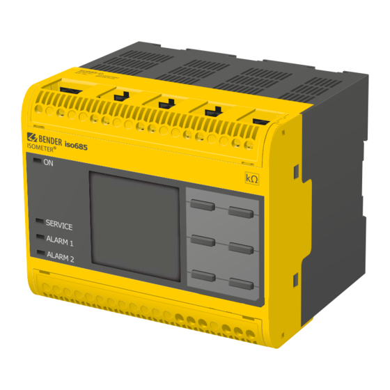
3. Device overview 3.2 Device variants The device version iso685-D-B features a high-resolution graphical LC display and control elements for direct operating of the device functions. iso685-D-B: Device version iso685-S-B neither features a display nor operating controls. It can only be used in combination with FP200 and is indirectly operated via iso685-S-B: this front panel. -
Page 13: Connections And Panel
LED display: ON/OFF Display Menu Reset Test Data Info LED display: SERVICE, ALARM 1, ALARM 2 X3 Optional expansion module for Bender devices Bottom Digital interface Ethernet interface Selectable resistance R 11 12 14 Connector for alarm relay 1 21 22 24 Connector for alarm relay 2 iso685-D-B_D00177_01_M_XXEN/01.2016... -
Page 14: Mounting
4. Mounting 4.1 Screw mounting 4.2 DIN rail mounting 15. Fix the three mounting clips delivered with the device (two of them packed 1. Fix the three mounting clips delivered with the device (two of them packed separately) manually or using a tool, as illustrated below. separately) manually or using a tool, as illustrated below. -
Page 15: Connection
5. Connection 5.1 Connection conditions Risk of property damage due to unprofessional installation! Consider the minimum distance to adjacent devices: If more than one insulation monitoring device is connected to a lateral 0 mm, top 20 mm, bottom 20 mm. conductively connected system, the system can be damaged. -
Page 16: Connection To A 3(N)Ac System/System Type 3Ac
5. Connection 5. Connection 5.2 Connection to a 3(N)AC system/system type 3AC 5.3 Connection to an AC system/system type AC Risk of injury, fire and damage to property due to a short- Risk of injury, fire and damage to property due to a short- circuit! circuit! According to DIN VDE 0100-430,devices used to protect against a... -
Page 17: Connection To A Dc System/System Type Dc
5. Connection 5. Connection 5.4 Connection to a DC system/system type DC 5.5 Connection to the X1 interface Risk of injury, fire and damage to property due to a short-cir- cuit! According to DIN VDE 0100-430,devices used to protect against a short-circuit when terminals L1/+, L2 und L3/- are coupled to the IT system to be monitored can be omitted if the wiring is carried out WARNING... -
Page 18: Connection To The Supply Voltage
5. Connection 5.6 Connection to the supply voltage 5.6.2 Connection to X1 5.6.1 Connection to A1/+, A2/- External Power supply for powering ISOMETER®s via terminal X1 must fulfil immunity and emission standards of the required appli- cation. For wiring longer than 1 m the use of a shielded cable is Danger of damage to property due to faulty connections! prescribed. -
Page 19: Connection To The Ethernet Interface
5. Connection 5.7 Connection to the Ethernet interface 5.8 Connection to the relay 1 interface (11 12 14) Relay 1 Common contact Normally closed (n.c) Normally open (n.o) Position the terminal cover and click it into place. Position the terminal cover and click it into place. iso685-D-B_D00177_01_M_XXEN/01.2016... -
Page 20: Connection To The Relay-2 Interface (21 22 24)
5. Connection 6. Commissioning 6.1 Device buttons 5.9 Connection to the relay-2 interface (21 22 24) You can adjust the device settings in the respective menu using the menu buttons. Depending on the menu entry, one of the options displayed below are assigned to the buttons. -
Page 21: Initial Commissioning
6. Commissioning 6.3.2 Set time and date After setting the response value R for Alarm 2, the device starts a self-test, Alarm messages in the history memory and the insulation resistance value over makes the first measurement and outputs the measured insulation resistance val- time can only be assigned correctly to the isoGraph when the date and time are ues of the IT system being monitored, then commissioning is completed. -
Page 22: Set Profile
6. Commissioning 6.3.4 Set profile 6.3.6 Set response value for Alarm 2 In order to adapt the insulation monitoring device optimally to the system to be You can set the response value for the main alarm here. monitored, you can select a profile here that suits your system. For an overview of A value of 50 Ω/V is recommended for the main alarm. -
Page 23: Display
7. Display 7.1 Standarddisplay 7.2 Fault display (active) In normal operation the ISOMETER® iso685-D-B displays the message OK and be- An active fault is displayed by . The upper part of the display will become or- low the currently measured insulation resistance. ange and displays the fault message. -
Page 24: Fault Display (Inactive)
7. Display If several fault messages occur, you can navigate through the faults using the 7.3 Fault display (inactive) button. In addition to the type of fault and the associated alarm value, An inactive fault is displayed by . If several faults have occurred, the number of you can see when the fault has occurred and how long it has been active. -
Page 25: Acknowledge Fault Message
7. Display 7.4 Acknowledge fault message 7.5 Data-isoGraph In order to acknowledge the fault message and return to the standard display of The isoGraph represents the chronological sequence of the insulation resistance the iso685-D-B ISOMETER®, all faults must be acknowledged by means of the reset over time. -
Page 26: History Memory
7. Display 7.6 History memory Up to 1023 alarm messages and device errors are stored in the history memory with date and time stamp. When the history memory is deleted, the minimum in- sulation resistance R will also be reset under Menu / Data Measured values / Data - Insulation. -
Page 27: Menu
8. Menu 1. Alarm settings 5. Buzzer 1. Insulation alarm 1. TEST 1. Alarm1 2. Function 1 2. Alarm2 3. Function 2 3. Memory 4. Function 3 6. Analog 2. Profile 1. Mode 3. System type 2. Scale centre 4. ISONet 3. -
Page 28: Alarm Settings
8. Menu Alarm settings Profile The limit values for the insulation resistances of Alarm 1 and Alarm 2 can be spec- Adapt the applicabilty of the ISOMETER® iso685-D-B to your system profile. For a ified in the alarm settings menu and can be adapted to the iso685-D-B ISOMETER® description of the profiles refer to “Profile overview”... -
Page 29: Device
8. Menu Device 1.8.1.2 t(on) Set the insulation resistance measurement function of the ISOMETER® iso685-D-B The response time t(on) after a switch-off signal can be set between 100 and 300 to active or inactive: milliseconds. For a description of the operating modes refer to “Digital input mo- de”... -
Page 30: Outputs
8. Menu Outputs 1.9.1.3 Function 1 The ISOMETER® iso685-D-B provides a total of six outputs: Select the appropriate setting for function 1. The following parameters can be set. The following parameters can be set for the outputs: For a detailed functional description refer to “Description of the output functions”... -
Page 31: Digital 1
8. Menu 1.9.3 Digital 1 1.9.5.1 TEST The following parameters can be set for each of the digital outputs: The functional test of the buzzer can be activated or deactivated. This only applies to the manual test and not to the cyclic device self-test: 1.9.3.1 TEST The functional test of the digital output can be activated or deactivated. -
Page 32: Scale Centre
8. Menu 1.9.6.2 Scale centre Data measured values Select the appropriate scale centre. The following parameters can be set. For a de- The ISOMETER® iso685-D-B stores certain measured values for a specific period of tailed description refer to “Description of the analogue output” on page time. -
Page 33: Device Settings
8. Menu Device settings 5.2.3 Summer time The device settings menu allows you to configure the basic settings for the ISO- Summer time can be considered in the following settings: METER® iso685-D-B: No automatic change between summer time and standard time. •off Language Daylight Saving Time... -
Page 34: Utc
8. Menu 5.2.8 UTC 5.3.2.4 Std. GW Configure the time according to UTC (Coordinated Universal Time) For Germany, If you use a standard gateway, enter the address here. Ensure that the IP address set +1 for winter time (MEZ) and +2 for summer time (MESZ). of the standard gateway suits the subnet mask, so that the ISOnet function can op- erate correctly. -
Page 35: Ttl For Subscription
•Restore For Retrofit only. For further information please contact the Bender-Service. Service Display The service menu can only be accessed by Bender Service staff. The display brightness of the ISOMETER® iso685-D-B can be adjusted in the "Dis- play" menu: Info In the menu "Info"... -
Page 36: Device Communication
Data can be read out with a read command on a register address. With a write command, data can be written into a register address. The register addresses BCOM is intended for communication of Bender devices via Ethernet of the individual measured values und parameters can be found in the annex All devices that communicate over BCOM must have the same system name. -
Page 37: Web Server
9. Device communication 9.4 Web server The web server of the device ISOMETER® iso685 represents the device functions graphically. The web server can be used to read out measured values and also for parameter setting. A maximum of 5 TCP/IP connections can be used simultaneously. Only one device may access the web server at the same time. -
Page 38: Special Functions For Coupled It Systems
10. Special functions for coupled IT systems 10.1 Particularities when monitoring coupled IT systems 10.2 System isolation via digital input with two coupled When using ISOMETER®s in IT systems, make sure that only one active ISOMETER® systems is connected in each interconnected system. If IT systems are interconnected via coupling switches, make sure that ISOMETER®s not currently used are disconnected from the IT system and deactivated. -
Page 39: System Isolation Via Digital Input With Several Coupled Systems
10. Special functions for coupled IT systems 10.3 System isolation via digital input with several coupled 10.4 System isolation via ISOnet systems IT-System 1 IT-System 2 In order to deactivate the ISOMETER® iso685-D-B via one of the digital inputs, the coupling switch must have a free contact. IT-System 1 IT-System 2 IT-System 1... - Page 40 10. Special functions for coupled IT systems For the ISOnet function, the following settings are made in the menu: If the ISOnet function is deactivated on an ISOMETER® in an ISOnet Alarm settings -> ISONet -> ISONet = BCOM. The ISOnet function of all ISOMETER®s existing in the system has to be activated interconnection, it will measure permanently and will not forward and the number of devices has to be determined.
-
Page 41: Settings
11. Settings 11.1 Profile overview System Nominal system Power Measuring leakage Description voltage frequency voltage capacitance Main circuits without dynamic frequency changes. AC 0…690 V/ The universal profile is suitable for all systems primarily with constant system Power circuits 15…460 Hz µF ±... -
Page 42: Settings Insulation Alarm
11. Settings 11.2 Settings insulation alarm Response time t(on) / t(off ) after a switch-off •active low Activation or deactivation of the two alarm levels R (Alarm 1) and R (Alarm signal. 2) are illustrated in the following graphic: An alarm will become inactive as soon as +25 % +0.5 kΩ of the set operating value is exceeded. -
Page 43: Digital Output Modes
11. Settings The following output functions are possible: 11.5 Digital output modes The function is not used. The following settings can be used to set the operating mode for the digital out- •off put: The status of the output changes when the value falls •Iso. -
Page 44: Description Of The Analogue Output
11. Settings 11.7.2 Midscale The status of the output changes in the event of an inter- Select the appropriate midscale. The following parameters can be set: •Device error nal device error. The switching signal is linear to the insulation resist- •Linear The status of the output changes on the occurrence of any •Common alarm... -
Page 45: Function
11. Settings 11.7.3 Function Select the appropriate setting for function. The following parameters can be set: Depending on the measured insulation value, an ana- •Insulation value logue current or voltage signal is provided at the output. Depending on the measured DC shift, an analogue current •DC shift or voltage signal is provided at the output. -
Page 46: Diagrams
12. Diagrams 12.1 Response time profile power circuits Response time as a function of the response value (R ) and system leakage capacitance (C ) according to IEC 61557-8 (U = AC 690 V, f = 50 Hz) ≤ 150 µF ≤... -
Page 47: Response Time Profile Generator
12. Diagrams 12.3 Response time profile generator Response time as a function of the response value (R ) and system leakage capacitance (C ) according to IEC 61557-8 (U = AC 690 V, f = 50 Hz) ≤ 5 µF ≤... -
Page 48: Response Time Profile Inverter > 10 Hz
12. Diagrams 12.5 Response time profile inverter > 10 Hz Response time as a function of the response value (R ) and system leakage capacitance (C ) according to IEC 61557-8 (U = AC 690 V, f = 50 Hz) ≤... -
Page 49: Relative Uncertainty
12. Diagrams 12.7 Relative uncertainty Relative uncertainty as a function of the response value (R ) and system leakage capacitance (C ) according to IEC 61557-8 (U = AC 690 V, f = 50 Hz) 100 % 90 % ≤ 1000 µF 80 % 70 % 60 %... -
Page 50: Alarm Messages
• Press the test button earth (PE) mode The device is in maintenance Service mode active! • Contact Bender Service SERVICE lights up condition • Check measured system capacitance or system frequency in the Profile does not suit the Wrong profile selected for this Info menu Chapter 11.1/... - Page 51 13. Alarm messages General fault at ISOnet, which is not covered by "Num.IsoNet devices" and "Failure address". For example, • Check Ethernet connection Disturbance isoNet sending messages can fail or • Check device function another device cannot process a message. iso685-D-B_D00177_01_M_XXEN/01.2016...
-
Page 52: Technical Data
14. Technical data 14.1 Data in tabular form Time response at R = 0.5 x R = 10 kΩ) and C Response time t = 1 μF according to IEC 61557-8 ..........()* = Factory setting ..........................profile dependent, typ. 4 s (see diagrams) ** = Indication limited outside the temperature range -25…+55 °C Startup delay T ............................ - Page 53 14. Technical data Digital inputs Switching elements Number ....................................3 Number of switching elements ......................2 changeover contacts Operating mode, adjustable......................... active high, active low Operating mode ........................N/C operation*/N/O operation Functions..................none, test, reset, start measurement, deactivate device Contact 11-12-14............none, Alarm 1, Alarm 2, connection fault, Alarm DC-, Alarm DC+, Voltage.........................Low DC -3…5 V, High DC 11…32 V .........
-
Page 54: W Option
14. Technical data Connection Dimensions (W x H x D) ..........................108 x 93 x 110 mm Weight ..................................< 390 g Connection type..................pluggable screw terminal or push-wire terminal Screw-type terminal: Option "W" data different from the standard version Nominal current................................≤ 10 A Ambient temperatures............................ -
Page 55: Ordering Details
14. Technical data 14.4 Ordering details Suitable system components Description Type Art. No. Supply voltage U Type Art. No. 7204-1421 B 986 763 AC 100…240 V; 47…460 Hz Appropriate measuring instruments iso685-D-B B 91067020 DC 24 V, 100…240 V SKMP : 28 kΩ,120 kΩ... -
Page 56: Index
Index Accessories 55 DC system 17 Alarm 42 Ethernet interface 19 Alarm 1 10 Relay 1 interface (11 12 14) 19 Alarm 2 10 Relay 2 interface (21 22 24) 20 Alarm settings 28 Supply voltage 18 Insulation alarm 42 X1 interface 17, 18 Messages 50 Control circuits 41... - Page 57 Index iso685-D-B 9 Minimum current rectifier 15 ISOnet 39 Minimum distance 15 Modbus/TCP 36 Hazards when handling the device 8 History memory 26 Nominal system voltage 9, 41, 52 Nominal voltage 7, 15 Normal operation 23 Inputs 29, 42 Inspection 8 Installation Operating mode 31, 42 DIN rail mounting 14...
- Page 58 Index Profile generator 47 Start initial measurement 32 Profile high capacitance 47 Start-up delay 29 Profile inverter 10 Hz 48 Storage 8 Profile power circuits 46 Supply voltage 52 Relative uncertainty 49 System isolation via digital input with two coupled systems 38 Response value 9, 52 System leakage capacitance 7, 9, 41 Safety instructions 7...
- Page 59 Londorfer Straße 65 • 35305 Gruenberg • Germany Carl-Benz-Straße 8 • 35305 Gruenberg • Germany Tel.: +49 6401 807-0 Tel.: +49 6401 807-760 Fax: +49 6401 807-259 Fax: +49 6401 807-629 Email: info@bender.de Email: info@bender-service.com Web: www.bender.de Web: http://www.bender.de Fotos: Bender Archiv und bendersystembau Archiv.
Need help?
Do you have a question about the ISOMETER iso685W-S-B and is the answer not in the manual?
Questions and answers