Advertisement
Available languages
Available languages
Quick Links
取取扱説明書/Manual
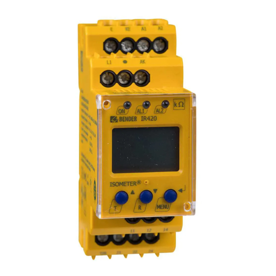
ISOMETER® IR420-D6
絶縁監視装置
用途
オフライン用絶縁監視装置"IR420-D6"は、電源が切れた停止中
の負荷の絶縁抵抗をモニターします。例えば、排水ポンプ、消火
ポンプ、エレベータのモーターや非常用発電機などは間欠的に
動作するか、常時停止状態にありますが、その停止中の絶縁抵
抗値を測定します。また、低圧負荷の他、カップリングデバイス
AGH520Sを使用すれば、最大7.2kVの高電圧負荷にも適用でき
ます。
尚、測定する為には単相/3相共、停止中にモーター巻線を通じ
て全ての相に低いインピータンスによる導通が必要です。
導通がない場合は、スターポイント誘導カップリングデバイス
DS2-31 又は、誘導負荷 AG70 を使用すれば適用できます。
適用できる回路の最大対地漏れキャパシタンスCeは、10μFとな
ります。10μFを超える場合は、Bender社の他の製品を使用する
ことになります。
安全に使う為に
電気の知識を充分に有している専門技術者や
工事会社により、設計、設置、試験、運転を
行って下さい。
感電の危険!
充電部を触れることにより、以下のリスクがあ
ります。 :
危険
•感電
•電気設備の損傷
• 絶縁監視モニターの故障や損壊
本モニターを設置する際には、必ず電源を切
り、オフ状態で行ってください。また、正しく設
置、及び配線接続をされていることを確認して
下さい。
最後に、"Bender製品を安全にご使用頂く為に"が貼付されてい
ますので、本取扱説明書の一部としてご熟読下さい。
本機を使用する際の注意事項
不完全な設置による事故・不具合発生の
リスク!
モニターする回路に複数の絶縁監視モニター
警告
がある場合、絶縁監視モニターは損傷する可
能性があります。また、損傷に至らない場合で
も、正しく機能はしなく、絶縁が低下しても正し
くアラームを発しません。モニターする回路系
統には、一つの絶縁監視モニターのみ接続さ
れていることを必ず確認して下さい。
高い電圧を印加しないでください!
絶縁抵抗測定(いわゆるメガテスト)や高電圧試験を
行う際には、必ず、テスト電圧が印加されないよう絶
警告
縁監視モニターを切り離して下さい。印加された場
合、絶縁監視モニターが損傷する場合があります。
絶縁監視装置がアラームを発信した場合、そ
の絶縁低下の原因を出来るだけ早く取り除い
てください。
IR420-D6_D00117_04_M_DEEN/05.2018
Insulation monitoring device
JP
Intended use
The "Offline monitor" IR420-D6 monitors the insulation resist-
ance of deenergized loads. These loads, e.g. fire pumps, slide-
valves drives, elevator motors or emergency generators, either
temporarily deenergized or deenergized for the most time, are
supplied from TN, TT or IT systems. The maximum permissible
nominal voltage depends on the nominal contact voltage of the
N/C contact of K3 (switch-on contactor). The nominal voltage
range can be extended to AC 7200 V with the coupling device
AGH520S. A low-impedance connection between the active con-
ductors is necessary to correctly monitor the de-energised cables.
An inductive star-point coupling device DS2-31 and an inductive
load AG70 are available for the monitoring of de-energised
lines.The maximum permissible system leakage capacitance C
10 μF.
Safety instructions
DANGER
Part of the device documentation in addition to this manual is the
enclosed "Safety instructions for Bender products".
Device-specific safety information
CAUTION
CAUTION
Only qualified personnel are permitted to carry
out the work necessary to install, commission and
run a device or system.
Risk of electrocution due to electric shock!
Touching live parts of the system carries the risk of:
• An electric shock
• Damage to the electrical installation
• Destruction of the device
Before installing and connecting the device,
make sure that the installation has been de-en-
ergised. Observe the rules for working on electri-
cal installations.
Risk of property damage due to unprofes-
sional installation!
If more than one insulation monitoring device is
connected to a conductively connected system,
the system can be damaged. If several devices
are connected, the device does not function and
does not signal insulation faults. Make sure that
only one insulation monitoring device is con-
nected in each conductively connected system.
Ensure disconnection from the IT system!
When insulation or voltage tests are to be carried
out, the device shall be isolated from the system
for the test period. Otherwise the device may be
damaged.
In the event of an alarm message, the insulation
fault should be eliminated as quickly as possible.
is
e
1
Advertisement

Related Manuals for Bender ISOMETER IR420-D6 Series


Summary of Contents for Bender ISOMETER IR420-D6 Series
- Page 1 Observe the rules for working on electri- 置、及び配線接続をされていることを確認して cal installations. 下さい。 最後に、”Bender製品を安全にご使用頂く為に”が貼付されてい Part of the device documentation in addition to this manual is the enclosed "Safety instructions for Bender products". ますので、本取扱説明書の一部としてご熟読下さい。 本機を使用する際の注意事項 Device-specific safety information 不完全な設置による事故・不具合発生の Risk of property damage due to unprofes- リスク!...
- Page 2 ISOMETER® IR420-D6 絶縁監視モニターが、キャビネットなどの内部に If the ISOMETER® is installed inside a control cabi- 設置する場合には、アラームを発信時に認識が net, the insulation fault message must be audible できるように警報音やキャビネット表面にアラー and/or visible to attract attention. ムランプを設置してください。 機能 Function 絶縁監視モニター IR420 は、端子L1と接地間にDC測定電圧 ® The IR420 ISOMETER generates a DC measuring voltage which is を印加します。絶縁が低下した回路は端子L1と接地間に閉回路...
-
Page 3: Installation And Connection
ISOMETER® IR420-D6 設置と配線接続 Installation and connection Risk of fatal injury from electric shock! 感電による死亡事故につながる危険性! Touching live parts of the system carries the risk of 充電部に触ると感電の危険があります。本機を electric shock. Before fitting the enclosure and 設置、及び、接続作業する前に、必ず電源がオ 危険! DANGER working on the device connections, make sure that フとなり、回路が停止していることを確認してく... -
Page 4: Wiring Diagram
ISOMETER® IR420-D6 配線図 Wiring diagram 例: Examples: DC 400 V 接地E 接地E テスト/ テスト/ リセット リセット AC 230 V AG 70 接地E 接地E テスト/ テスト/ リセット リセット 3AC 400 V DS2-31 接地E テスト/ リセット IR420-D6_D00117_04_M_DEEN/05.2018... - Page 5 各極間/各相間にモーター巻線などの低イン connected in a low-impedance manner can lead WARNING 警告 ピーダンス抵抗で接続がされて導通があること to connection error messages and false が必要です。繋がれていない場合は、エラーを measurements. Please contact Bender experts 起こしたり正しく測定しません。その場合でのご when such an application arises. 使用はお問い合わせ下さい。 端子 説明 Terminal Connection 接地端子...
- Page 6 起動遅延タイマー t と動作遅延 Setting the starting delay t and タイマー ton の設定 response delay t パスワード設定、工場設定値へ Enabling or disabling password protec- 初期化、Benderサービス用メニュー tion, changing the password; (ロックされています) Reestablish the factory settings, service menu SyS blocked InF ハードウェア/ソフトウェア・バージョン情報 Calling up hardware and software versions ESC 上流メニューレベルへの移動...
- Page 7 ISOMETER® IR420-D6 工場設定値 Factory setting アラーム動作設定値 Ran1/Ran2: 1 MΩ / 100 kΩ (AL 1/2) Response values R 1 MΩ / 100 kΩ (AL 1/2) 動作モード K1/K2: 常時開モード(N/O) Operating mode K1/K2: N/O operation (n.o.) アラームメモリー機能: 無効 Fault memory: Starting deactivated 起動遅延タイマー: t = 0 s t = 0 s delay: Response delay:...
- Page 8 ISOMETER® IR420-D6 遅延タイマーの設定 Setting the time delay このメニューでは、動作遅延タイマー ton (0…99秒)と起動遅延 Use this segment to enter the response delay t (0…99 s) and タイマー t (0…10 秒)の設定が行えます。 the starting delay t (0…10 s). 設定を工場出荷時に戻す/パスワード保護 Reset to factory setting and password protection このメニューでは、パスワード有効/無効やパスワード変更が行...
- Page 9 ISOMETER® IR420-D6 試験と運用 Commissioning 試験と運用時には、本機が必ず正しく配線接続されていることを Prior to commissioning, check proper connection of the ISOMETER®. 確認してから行ってください。 It is recommended to carry out a functional test 地絡を模擬する為に、適切な実抵抗を用い、 using a genuine earth fault, e.g. via a suitable re- 実際に動作確認テストを行うことを推奨します! sistance! 技術仕様 IR420-D6.. Technical data IR420-D6.. ()* = 工場設定値...
- Page 10 ISOMETER® IR420-D6 リレー接点 Switching elements 数量 ....................2 個(接点 K1、K2) Number of..................2 (changeover contacts K1, K2) 接点の動作モード ............Operating principle........N/O operation, N/C operation (N/O operation n.o.)* 常時開、常時閉 (常時開) 接点寿命 ....................10000回動作 Electrical endurance ................10000 switching operations 接点仕様 (IEC 60947-5-1による): Contact data according IEC 60947-5-1 定格使用電圧...
- Page 11 ....................+ 15 % 電圧の裕度 U Tolerance U ...........................+ 15 % モード..........................DB Mode...............................DB 絶縁階級 ........................B Insulation class ..........................B 使用温度 ....................-25°C…+70 °C Operating temperature ..................-25 °C…+70 °C オーダー情報 Ordering details タイプ/Type Bender社製品番号/Art. No. B984718 AG70 誘導負荷 IR420-D6_D00117_04_M_DEEN/05.2018...
- Page 12 Subject to change! メール:inquiry@protrad.jp © Bender GmbH & Co. KG Bender GmbH & Co. KG Tel.: +49 6401 807-0E-Mail: info@bender.de • • Londorfer Str. 65 35305 Grünberg Germany Fax: +49 6401 807-259Web: http://www.bender.de • • Postfach 1161 35301 Grünberg Germany IR420-D6_D00117_04_M_DEEN/05.2018...
- Page 13 Bender製品を安全にご使用頂く為に このリーフレットはBender製品を安全に使用頂くための Bender製品を使用する場合は、以下のスキルを有した技 安全事項が記載されています。本体に付属しています取 術者、又は、施工者が行うことを守って下さい。: - 安全についてのBender社の記述内容を理解できる。 扱説明書と共に熟読をお願い致します。 - 取扱説明書の内容を理解できる。 シンボルについて - 最新の規格、法律を理解している。 取扱説明書の中で、重要な個所をより理解しやすいよう 製品を設置する場合は、対象回路が必ず電源が落ちてい に内容を、下記のシンボルにて内容を重複して記述して ることを確認して下さい。 あります。シンボルを意味することは、下記の通りで また、製品を接続する際には、取扱説明書に従った配線、 す。: 接続を行って下さい。取扱説明書や技術資料、安全記述 を守らず使用することは、決して行わないでください。 それらのことを行った場合は、故障の原因になるばかり 危険: このマークのある記述内容は、感電死 でなく、怪我、感電、火事、設備の損傷につながる可能 や重症に至る非常に高い危険が存在すること 性があります。 を示します。 危険 警告:このマークのある記述内容は、場合に 一般的な安全要求事項 よっては事故 死や重症に至る高い危険が存 感電の危険! 在することを示します。 警告 充電した導体部分に触れた場合、感電死や 重症に至る場合があります。それらに人体 の接触が発生しないよう、また、感電に対...
Need help?
Do you have a question about the ISOMETER IR420-D6 Series and is the answer not in the manual?
Questions and answers