HP 280 G4 Maintenance And Service Manual
Small form factor business pc
Hide thumbs
Also See for 280 G4:
- Disassembly instructions manual (7 pages) ,
- Maintenance and service manual (124 pages) ,
- Product end-of-life disassembly instructions (7 pages)
Table of Contents
Advertisement
Advertisement
Table of Contents

Related Manuals for HP 280 G4


Summary of Contents for HP 280 G4
- Page 1 Maintenance and Service Guide HP 280 G4 Small Form Factor Business PC...
- Page 2 HP Inc. bound by the terms of the HP End User License Not all features are available in all editions of under license. Intel, Core, Pentium, and Celeron Agreement (EULA).
-
Page 3: About This Guide
About this guide WARNING! Indicates a hazardous situation that, if not avoided, could result in serious injury or death. CAUTION: Indicates a hazardous situation that, if not avoided, could result in minor or moderate injury. IMPORTANT: Indicates information considered important but not hazard-related (for example, messages related to property damage). - Page 4 About this guide...
-
Page 5: Table Of Contents
Table of contents 1 Product features ............................1 Standard configuration features ........................... 1 Front panel components ............................2 Rear panel components ............................3 2 Illustrated parts catalog ..........................4 Computer major components ..........................4 Cables ..................................6 Miscellaneous parts ............................... 7 3 Routine care, SATA drive guidelines, and disassembly preparation .............. - Page 6 4 Removal and replacement procedures ......................16 Preparation for disassembly ..........................16 Rubber feet ................................17 Access panel ................................. 18 Expansion card ..............................19 Drives ................................... 22 Optical drive ............................22 Hard drive ............................24 Front bezel ................................26 WLAN module ..............................27 Solid-state drive module .............................
- Page 7 Using HP PC Hardware Diagnostics UEFI ......................86 Starting HP PC Hardware Diagnostics UEFI ..................87 Downloading HP PC Hardware Diagnostics UEFI to a USB flash drive ..........87 Downloading the latest HP PC Hardware Diagnostics UEFI version ......87 Downloading HP PC Hardware Diagnostics UEFI by product name or number (select products only) .....................
- Page 8 Backing up information and creating recovery media ..................90 Using Windows tools ......................... 90 Using the HP Cloud Recovery Download Tool to create recovery media (select products only) ..90 Restoring and recovery ............................91 Restoring, resetting, and refreshing using Windows tools .............. 91 Recovering using HP Recovery media ....................
-
Page 9: Product Features
Standard configuration features Features may vary depending on the model. For support assistance and to learn more about the hardware and software installed on your computer model, run the HP Support Assistant utility. NOTE: This computer model can be used in a tower orientation or a desktop orientation. -
Page 10: Front Panel Components
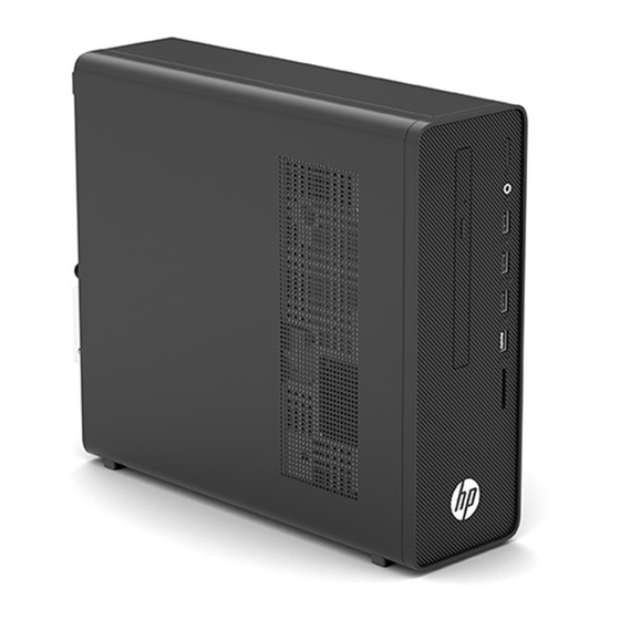
Front panel components Drive configuration may vary by model. Table 1-1 Identifying the front panel components Front panel components Optical drive (optional) USB SuperSpeed ports (4) Power button SD media card reader Audio-out (headphone)/Audio-in (microphone) combo jack NOTE: The power light is normally white when the power is on. If it is flashing red, there is a problem with the computer and it is displaying a diagnostic code. -
Page 11: Rear Panel Components
Rear panel components Table 1-2 Identifying the rear panel components Rear panel components Line-out connector for powered audio devices RJ-45 network connector (green) Line-in audio connector (blue) Power cord connector VGA monitor connector* Serial port (select products only) HDMI port* Security lock slot USB ports (4) NOTE:... -
Page 12: Illustrated Parts Catalog
Illustrated parts catalog Computer major components This chapter provides part information for all chassis. Table 2-1 Computer major components and their descriptions Item Description Access panel Fan sink (includes replacement thermal material) Graphics card NVIDIA® GeForce® GT 730 graphics card, 2 GB AMD Radeon™... - Page 13 Table 2-1 Computer major components and their descriptions (continued) Item Description PCIe ×1-to-RS-232 (serial) Intel PRO/1000 single port GbE NIC Fan duct System board (includes replacement thermal material) Power supply 180 W 160 W Computer chassis Hard drive, 3.5 inch 2 TB, 7200 rpm 1 TB, 7200 rpm 500 GB, 7200 rpm...
-
Page 14: Cables
Table 2-1 Computer major components and their descriptions (continued) Item Description Intel Core i7-9700 (3.0 GHz, 12 MB cache, 8 cores, 65 W) Intel Core i5-9600 (3.1 GHz, 9 MB cache, 6 cores, 65 W) Intel Core i5-9500 (3.0 GHz, 9 MB cache, 6 cores, 65 W) Intel Core i5-9500F (3.0 GHz, 9 MB cache, 6 cores, 65 W) Intel Core i5-9400 (2.9 GHz, 9 MB cache, 6 cores, 65 W) Intel Core i5-9400F (2.9 GHz, 9 MB cache, 6 cores, 65 W) -
Page 15: Miscellaneous Parts
USB antimicrobial mouse (China only) USB hardened mouse (India only) Keyboard USB, slim USB, Essential USB, Katydid USB, business, grey, slim HP, antimicrobial, slim Keyboard country codes Table 2-4 Keyboard country codes For use in country Spare part For use in country... -
Page 16: Routine Care, Sata Drive Guidelines, And Disassembly Preparation
Routine care, SATA drive guidelines, and disassembly preparation This chapter provides general service information for the computer. Adherence to the procedures and precautions described in this chapter is essential for proper service. IMPORTANT: When the computer is plugged into an AC power source, voltage is always applied to the system board. -
Page 17: Preventing Electrostatic Damage To Equipment
Table 3-1 Static electricity occurrence based on activity and humidity (continued) Relative humidity Removing DIPs from vinyl tray 2,000 V 4,000 V 11,500 V Removing DIPs from polystyrene foam 3,500 V 5,000 V 14,500 V Removing bubble pack from PCB (printed circuit board) 7,000 V 20,000 V 26,500 V... -
Page 18: Grounding The Work Area
● Use field service tools, such as cutters, screwdrivers, and vacuums, that are conductive. Recommended materials and equipment HP recommends the following materials and equipment to prevent static electricity: Antistatic tape ● Antistatic smocks, aprons, or sleeve protectors ●... -
Page 19: Operating Guidelines
Operating guidelines To prevent overheating and to help prolong the life of the computer: Keep the computer away from excessive moisture, direct sunlight, and extremes of heat and cold. ● Operate the computer on a sturdy, level surface. Leave a 10.2 cm (4 inch) clearance on all vented sides of ●... -
Page 20: Cleaning The Keyboard
After cleaning, always wipe the unit with a clean, lint-free cloth. ● ● Occasionally clean the air vents on the computer. Lint and other foreign matter can block the vents and limit the airflow. Cleaning the keyboard Follow all safety precautions in General cleaning safety precautions on page 11 before cleaning the keyboard. -
Page 21: Tool Requirements
If an incorrect screw is used during the reassembly process, it can damage the unit. HP strongly recommends that all screws removed during disassembly be kept with the part that was removed and then returned to their proper locations. -
Page 22: Sata Hard Drives
Do not dispose of batteries, battery packs, and accumulators with general household waste. In order to forward them to recycling or proper disposal, please use the public collection system or return them to HP, their authorized partners, or their agents. - Page 23 Keep cables away from major heat sources like the heat sink. ● ● Keep cables clear of sliding or moveable parts to prevent them from being cut or crimped when the parts are moved. When folding a flat ribbon cable, never fold to a sharp crease. Sharp creases may damage the wires. ●...
-
Page 24: Removal And Replacement Procedures
Removal and replacement procedures Adherence to the procedures and precautions described in this chapter is essential for proper service. After completing all necessary removal and replacement procedures, run the Diagnostics utility to verify that all components operate properly. NOTE: Not all features listed in this guide are available on all computers. Preparation for disassembly WARNING! Voltage is always present on the system board when the computer is plugged into an active AC... -
Page 25: Rubber Feet
Rubber feet Prepare the computer for disassembly (Preparation for disassembly on page 16). Position the computer upside down. Slide the feet away from the chassis to remove them. To install the rubber feet, reverse the removal procedures. Rubber feet... -
Page 26: Access Panel
Access panel Prepare the computer for disassembly (Preparation for disassembly on page 16). Loosen the captive Phillips screw (1), slide the access panel toward the back of the computer, and then lift it off (2). To install the access panel, reverse the removal procedure. Chapter 4 Removal and replacement procedures... -
Page 27: Expansion Card
Expansion card For a list of available expansion cards, see Computer major components on page The computer has one PCI Express ×1 expansion socket and one PCI Express ×16 expansion socket. NOTE: You can install a PCI Express ×1, ×4, ×8, or ×16 expansion card in the PCI Express ×16 socket. For dual graphics card configurations, the first (primary) card must be installed in the PCI Express ×16 socket. - Page 28 If you are removing a PCI Express ×1 card, hold the card at each end, and carefully rock it back and forth until the connectors pull free from the socket. Pull the expansion card straight up from the socket. If you are removing a PCI Express ×16 card, pull the retention arm on the back of the expansion socket away from the card (1), and carefully rock the card back and forth until the connectors pull free from the socket.
- Page 29 To install a new expansion card (PCI Express ×16 shown), hold the card just above the expansion socket on the system board, and then move the card toward the rear of the chassis so that the bracket on the card is aligned with the open slot on the rear of the chassis. Press the card straight down into the expansion socket on the system board.
-
Page 30: Drives
Drives For a list of available drives, see Computer major components on page When installing drives, follow these guidelines: The primary Serial ATA (SATA) hard drive must be connected to the dark blue primary SATA connector on ● the system board labeled SATA0. Connect an optical drive to the white SATA connector on the system board labeled SATA1. - Page 31 Press the green lever to disengage the drive from the drive bay (3), and then slide the optical drive out of the front of the computer (4). To install the optical drive, reverse the removal procedure. Drives...
-
Page 32: Hard Drive
Hard drive The hard drive is located in the drive cage, above the optical drive. You must remove the drive cage to remove the hard drive. You must remove the optical drive to remove the drive cage. NOTE: Before you remove the old hard drive, be sure to back up the data from the old hard drive so that you can transfer the data to the new hard drive. - Page 33 To remove a hard drive from the drive cage, remove the four screws that secure the drive to the drive cage (1), and then slide the drive out of the cage (2). To install a hard drive, reverse the removal procedures. Drives...
-
Page 34: Front Bezel
Front bezel Prepare the computer for disassembly (Preparation for disassembly on page 16). Remove the access panel (Access panel on page 18). Remove the optical drive (Optical drive on page 22). Pull the four tabs upward (1), and then rotate the bezel off the computer (2). IMPORTANT: A cable connects the power button in the bezel to the system board. -
Page 35: Wlan Module
WLAN module The WLAN module is located under the drive cage. For a list of available WLAN modules, see Computer major components on page Prepare the computer for disassembly (Preparation for disassembly on page 16). Remove the access panel (Access panel on page 18). -
Page 36: Solid-State Drive Module
Solid-state drive module The M.2 solid-state drive module is located under the drive cage. For a list of available solid-state drives, see Computer major components on page Prepare the computer for disassembly (Preparation for disassembly on page 16). Remove the access panel (Access panel on page 18). -
Page 37: Memory
Memory For a list of available memory modules, see Computer major components on page The computer comes with double data rate 4 synchronous dynamic random access memory (DDR4-SDRAM) dual inline memory modules (DIMMs). DIMMs The memory sockets on the system board can be populated with up to two industry-standard DIMMs. These memory sockets are populated with at least one preinstalled DIMM. -
Page 38: Removing And Installing Dimms
assigned to single channel. If one channel will have more memory than the other, assign the larger amount to Channel A. In any mode, the maximum operational speed is determined by the slowest DIMM in the system. ● Removing and installing DIMMs IMPORTANT: You must disconnect the power cord and wait approximately 30 seconds for the power to drain before adding or removing memory modules. -
Page 39: Rtc Battery
The lithium battery is only used when the computer is not connected to AC power. HP encourages customers to recycle used electronic hardware, HP original print cartridges, and rechargeable batteries. For more information about recycling programs, go to http://www.hp.com/recycle. -
Page 40: Fan Duct
Fan duct The fan duct sits on the fan sink and is secured to the fan sink with tabs. Prepare the computer for disassembly (Preparation for disassembly on page 16). Remove the access panel (Access panel on page 18). Remove the power supply cable from the clips on the duct. Pull the tabs away from each other (1), and then lift the duct off the fan sink (2). -
Page 41: Fan Sink
Fan sink IMPORTANT: The bond between the fan sink and the processor may be very tight. If the computer will power on, before removing the fan sink, turn on the computer until it warms the fan sink. Warming the fan sink loosens the bond between the heat sink and the processor, thereby making separating them easier. -
Page 42: Processor
After installing a new processor onto the system board, always update the system ROM to ensure that the latest version of the BIOS is being used on the computer. The latest system BIOS can be found on the Web at: http://www8.hp.com/us/en/support-drivers.html. Chapter 4 Removal and replacement procedures... -
Page 43: Power Supply
WARNING! To reduce potential safety issues, use only the power supply provided with the computer, a replacement power supply provided by HP, or a power supply purchased as an accessory from HP with the computer. The power supply is located on the left side of the chassis. It is held in place by four Torx screws outside of the chassis. - Page 44 On the inside of the computer, press the power supply release button (2), and then lift the power supply out of the computer (3). To install the power supply, reverse the removal procedure. Chapter 4 Removal and replacement procedures...
-
Page 45: System Board
System board Prepare the computer for disassembly (Preparation for disassembly on page 16). Remove the optical drive (Optical drive on page 22). Remove the access panel (Access panel on page 18). Remove the front bezel (Front bezel on page 26). Remove the fan duct (Fan duct on page 32). -
Page 46: System Board Callouts
NOTE: When replacing the system board, you must also change the chassis serial number in the BIOS. IMPORTANT: When reconnecting the cables, be sure that they are positioned correctly. System board callouts Table 4-1 System board callouts Item Sys Bd Label Component Item Sys Bd Label... -
Page 47: Antenna Cable
Antenna cable The wireless antenna cable routes along the bottom of the computer chassis. Prepare the computer for disassembly (Preparation for disassembly on page 16). Remove the optical drive (Optical drive on page 22). Remove the access panel (Access panel on page 18). -
Page 48: Computer Setup (F10) Utility
Computer Setup (F10) Utility Computer Setup (F10) utilities Use Computer Setup (F10) Utility to do the following: ● Change settings from the defaults or restore the settings to default values. View the system configuration, including settings for processor, graphics, memory, audio, storage, ●... - Page 49 Use the arrow (left and right) keys to select the appropriate heading. Use the arrow (up and down) keys to select the option you want, then press enter. To return to the Computer Setup Utilities menu, press esc. To apply and save changes, select Main > Save Changes and Exit. If you have made changes that you do not want applied, select Ignore Changes and Exit.
-
Page 50: Computer Setup-Main
Computer Setup–Main NOTE: Support for specific Computer Setup options can vary depending on the hardware configuration. Table 5-1 Computer Setup—Main Option Description Main System time ● Select to change. ● System date Select to change. Product name ● ● System family System board ID ●... -
Page 51: Computer Setup-Configuration
Table 5-2 Computer Setup—Security (continued) Option Description Intel Software Guard Lets you configure SGX. Default is S/W Controlled. Extensions (SGX) TPM Device Lets you set the Trusted Platform Module as Available or Hidden. If set to Hidden, the TPM device is not visible to the operating system. -
Page 52: Computer Setup-Exit
Table 5-4 Computer Setup—Boot Options Option Heading POST Hotkey Delay (sec) Setting to a non-zero value adds a delay during POST. This option can be necessary for certain add-in peripherals that respond slowly or violate specifications. Default is 0. USB Boot Lets you enable booting from a USB device. -
Page 53: Troubleshooting Without Diagnostics
● To assist you in resolving problems online, HP Instant Support Professional Edition provides you with self- solve diagnostics. If you need to contact HP support, use HP Instant Support Professional Edition's online chat feature. Access the Business Support Center (BSC) at http://www.hp.com/go/bizsupport... -
Page 54: Helpful Hints
If it becomes necessary to call for technical assistance, be prepared to do the following to ensure that your service call is handled properly: Be in front of your computer when you call. ● ● Write down the computer serial number, product ID number, and monitor serial number before calling. ●... -
Page 55: Solving General Problems
If you have installed an operating system other than the factory-installed operating system, check to be ● sure that it is supported on the system. If the system has multiple video sources (embedded, PCI, or PCI-Express adapters) installed (embedded ● video on some models only) and a single monitor, the monitor must be plugged into the monitor connector on the source selected as the primary VGA adapter. - Page 56 In case of forgotten password, power loss, or computer malfunction, you must manually disable the Smart Cover lock . A key to unlock the Smart Cover Lock is not available from HP. Keys are typically available from a hardware store.
- Page 57 Poor performance. Cause Solution Hard drive fragmented. Defragment hard drive. Program previously accessed did not release reserved memory Restart the computer. back to the system. Virus resident on the hard drive. Run virus protection program. Too many applications running. Close unnecessary applications to free up memory. Add more memory.
-
Page 58: Solving Power Problems
System does not power on and the LEDs on the front of the computer are not flashing. Cause Solution If equipped with a voltage selector, check that the voltage selector (located on the rear of the power supply) is set to the appropriate voltage. -
Page 59: Solving Hard Drive Problems
Computer powered off automatically and the Power LED flashes red four times and then white two times. Cause Solution If fan a plugged in and not spinning, replace it. Computer powered off automatically and the Power LED flashes red three times and then white four times. Cause Solution Power failure (power supply is overloaded). - Page 60 Drive not found (identified). Cause Solution Cable could be loose. Check cable connections. The system may not have automatically recognized a newly See reconfiguration directions in the Solving hardware installation installed device. problems on page 62 section. If the system still does not recognize the new device, check to see if the device is listed within Computer Setup.
-
Page 61: Solving Media Card Reader Problems
Computer seems to be locked up. Cause Solution Program in use has stopped responding to commands. Use the task manager to close programs that do not respond. Attempt the normal Windows “Shut Down” procedure. If this fails, press the power button for four or more seconds to turn off the power. -
Page 62: Solving Display Problems
Do not know how to remove a media card correctly. Cause Solution The computer’s software is used to safely eject the card. In Windows 10, type file in the taskbar search box, and then select File Explorer from the list of applications. In the left column, expand This PC, right-click on the corresponding drive icon, and then select Eject. - Page 63 Reseat DIMMs. Power on the system. Replace DIMMs one at a time to isolate the faulty module. Replace third-party memory with HP memory. Replace the system board. Blank screen and the power LED flashes red six times, once every second, followed by a two second pause, and the computer beeps six times.
- Page 64 Blank screen and the power LED flashes red six times, once every second, followed by a two second pause, and the computer beeps six times. (Beeps stop after fifth iteration but LEDs continue flashing.) Cause Solution Replace the system board. For systems with integrated graphics, replace the system board.
- Page 65 The picture is broken up, rolls, jitters, or flashes. Cause Solution Fluorescent lights or fans may be too close to the monitor. Monitor needs to be degaussed. Degauss the monitor. See the documentation that came with the monitor for instructions. Image is not centered.
-
Page 66: Solving Audio Problems
To download a SoftPaq that will assist you with the synchronization, go to the following website, select the appropriate monitor, and download either SP32347 or SP32202: http://www.hp.com/support Graphics card is not seated properly or is bad (some models). Reseat the graphics card. Replace the graphics card. - Page 67 Sound does not come out of the speaker or headphones. Cause Solution Software volume control is turned down or muted. Double-click the Speaker icon on the taskbar, make sure that Mute is not selected, and use the volume slider to adjust the volume.
-
Page 68: Solving Printer Problems
Line-in jack is not functioning properly. Cause Solution Jack has been reconfigured in the audio driver or application In the audio driver or application software, reconfigure the jack or software. set the jack to its default value. There is no sound or sound volume is too low. Cause Solution The application is set to use a different audio device than... -
Page 69: Solving Keyboard And Mouse Problems
Printer prints garbled information. Cause Solution The correct printer driver for the application is not installed. Install the correct printer driver for the application. The cables may not be connected properly. Reconnect all cables. Printer memory may be overloaded. Reset the printer by turning it off for one minute, and then turn it back on. -
Page 70: Solving Hardware Installation Problems
Mouse does not respond to movement or is too slow. Cause Solution Mouse connector is not properly plugged into the back of the Shut down the computer using the keyboard. computer. Windows 10: Press the Ctrl keys at the same time (or press the Windows logo key) to display the Start menu. - Page 71 A new device is not recognized as part of the system. Cause Solution Device is not seated or connected properly. Ensure that the device is properly and securely connected and that pins in the connector are not bent down. Cable(s) of new external device are loose or power cables are Ensure that all cables are properly and securely connected and unplugged.
-
Page 72: Solving Network Problems
Power LED flashes red three times and then white two times. Cause Solution Replace third-party memory with HP memory. Replace the system board. Solving network problems Some common causes and solutions for network problems are listed in the following table. These guidelines do not discuss the process of debugging the network cabling. - Page 73 Diagnostics reports a failure. Cause Solution The cable is not securely connected. Ensure that the cable is securely attached to the network connector and that the other end of the cable is securely attached to the correct device. The cable is attached to the incorrect connector. Ensure that the cable is attached to the correct connector.
-
Page 74: Solving Memory Problems
Management Engine (ME) settings). To avoid damage to the DIMMs or the system board, you must unplug the computer power cord before attempting to reseat, install, or remove a memory module. For those systems that support ECC memory, HP does not support mixing ECC and non-ECC memory. Otherwise, the computer will not boot the operating system. -
Page 75: Solving Cd-Rom And Dvd Problems
Memory is installed incorrectly or is bad. Reseat DIMMs. Power on the system. Replace DIMMs one at a time to isolate the faulty module. Replace third-party memory with HP memory. Replace the system board. Solving CD-ROM and DVD problems If you encounter CD-ROM or DVD problems, see the common causes and solutions listed in the following table or to the documentation that came with the optional device. - Page 76 Drive not found (identified). Cause Solution Cable could be loose. Check cable connections. The system may not have automatically recognized a newly See reconfiguration directions in the Solving hardware installation installed device. problems on page 62 section. If the system still does not recognize the new device, check to see if the device is listed within Computer Setup.
-
Page 77: Solving Usb Flash Drive Problems
CD-ROM, CD-RW, DVD-ROM, or DVD-R/RW drive cannot read a disc or takes too long to start. Cause Solution The DVD-ROM drive takes longer to start because it has to Wait at least 30 seconds to let the DVD-ROM drive determine the determine the type of media played, such as audio or video. -
Page 78: Solving Front Panel Component Problems
System will not boot from USB flash drive. Cause Solution Boot order is not correct. Run the Computer Setup utility and change boot sequence in Boot Options. Removable Media Boot is disabled in the Computer Setup utility. Run the Computer Setup utility and enable booting to removable media in Boot Options. -
Page 79: Solving Internet Access Problems
Solving Internet access problems If you encounter Internet access problems, consult your Internet Service Provider (ISP) or see the common causes and solutions listed in the following table. Unable to connect to the Internet. Cause Solution Internet Service Provider (ISP) account is not set up properly. Verify Internet settings or contact your ISP for assistance. - Page 80 Computer will not continue and the HP logo does not appear. Cause Solution ROM issue - POST error has occurred. Observe the beeps and LED lights on the front of the computer. POST error messages and diagnostic front panel LEDs and audible codes on page 73 to determine possible causes.
-
Page 81: Post Error Messages And Diagnostic Front Panel Leds And Audible Codes
POST error messages and diagnostic front panel LEDs and audible codes This appendix lists the error codes, error messages, and the various indicator light and audible sequences that you may encounter during Power-On Self-Test (POST) or computer restart, the probable source of the problem, and steps you can take to resolve the error condition. - Page 82 Control panel message Description Recommended action RTC (real-time clock) battery may need to problem persists, replace the RTC battery. See be replaced. the Removal and Replacement section for instructions on installing a new battery. 008–Microcode Patch Error Processor is not supported by the BIOS. Upgrade BIOS to proper version.
- Page 83 Run the Drive Protection erroneous error message.) System test under using F2 Diagnostics when booting the computer. Apply hard drive firmware patch if applicable. (Available at http://www.hp.com/support.) POST numeric codes and text messages...
- Page 84 System test under using F2 Diagnostics when booting the computer. Apply hard drive firmware patch if applicable. (Available at http://www.hp.com/support.) Back up contents and replace hard drive. 309 – 30C: Hard Disk 3–6: SMART Hard Drive Hard drive is about to fail. (Some hard drives...
- Page 85 Control panel message Description Recommended action Reconfigure card resources and/or run Computer Setup or Windows utilities. 419-Out of Memory Space for Option ROMs Recently added PCI expansion card contains an If a PCI expansion card was recently ▲ option ROM too large to download during POST. added, remove it to see if the problem remains.
-
Page 86: Interpreting System Validation Diagnostic Front Panel Leds And Audible Codes
Control panel message Description Recommended action 90B-Fan Failure The system has detected that a cooling fan is Reseat fan. not operating correctly. Reseat fan cable. Replace fan. 90D-System Temperature Thermal shutdown occurred. The system BIOS Make sure system has proper airflow. has detected your machine was previously shut down to avoid overheating. - Page 87 Table 7-1 Interpreting system validation diagnostic front panel LEDs and audible codes (continued) Number of long beeps/blinks Error category Hardware Thermal System board Patterns of blink/beep codes are determined by using the following parameters: 1 second pause occurs after the last major blink. ●...
- Page 88 Table 7-2 Interpreting system validation diagnostic front panel LEDs and audible codes (continued) Category Major/minor code Description The embedded controller rebooted the system after a possible lockup condition had been detected through the use of a System Health Timer, Automated System Recovery Timer, or other mechanism.
-
Page 89: Password Security And Resetting Cmos
If you lose or forget the password when in stringent security mode, the system can only be reset by System Management Command. This is a way for HP Service and Support to provide a secure method to access the BIOS and command a password reset for a specifically identified unit under the direction of the owner. This scenario may not be covered under warranty. -
Page 90: Resetting Cmos And/Or The Password Jumper
If you lose or forget the password when in stringent security mode, the system can only be reset by System Management Command. This is a way for HP Service and Support to provide a secure method to access the BIOS and command a password reset for a specifically identified unit under the direction of the owner. This scenario may not be covered under warranty. -
Page 91: Changing A Setup Or Power-On Password
Shut down the operating system properly, then turn off the computer and any external devices, and disconnect the power cord from the power outlet. With the power cord disconnected, press the power button again to drain the system of any residual power. -
Page 92: Deleting A Setup Or Power-On Password
When the key icon appears, type your current password, a slash (/) or alternate delimiter character, your new password, another slash (/) or alternate delimiter character, and your new password again as shown: current password/new password/new password NOTE: Type the new password carefully since the characters do not appear on the screen. Press Enter. -
Page 93: Using Hp Pc Hardware Diagnostics
The tool runs within the Windows operating system to diagnose hardware failures. If HP PC Hardware Diagnostics Windows is not installed on your computer, first you must download and install it. To download HP PC Hardware Diagnostics Windows, see... -
Page 94: Downloading The Latest Hp Pc Hardware Diagnostics Windows Version
To download HP PC Hardware Diagnostics Windows, follow these steps: Go to http://www.hp.com/go/techcenter/pcdiags. The HP PC Diagnostics home page is displayed. Select Download HP Diagnostics Windows, and then select a location on your computer or a USB flash drive. The tool downloads to the selected location. -
Page 95: Starting Hp Pc Hardware Diagnostics Uefi
If your PC does not start in Windows, you can use HP PC Hardware Diagnostics UEFI to diagnose hardware issues. When HP PC Hardware Diagnostics UEFI detects a failure that requires hardware replacement, a 24-digit Failure ID code is generated. For assistance in solving the problem: Select Contact HP, accept the HP privacy disclaimer, and then use a mobile device to scan the Failure ID ▲... -
Page 96: Downloading Hp Pc Hardware Diagnostics Uefi By Product Name Or Number (Select Products Only)
For some products, you might have to download the software to a USB flash drive by using the product name or number. To download HP PC Hardware Diagnostics UEFI by product name or number (select products only) to a USB flash drive: Go to http://www.hp.com/support. - Page 97 Set the location for downloading the diagnostic tools. This feature provides access to the tools from the ● HP website or from a server that has been preconfigured for use. Your computer does not require the traditional local storage (such as a hard drive or USB flash drive) to run remote diagnostics.
-
Page 98: 10 Backing Up, Restoring, And Recovering
You must be connected to the Internet to access the Get Help app. Using the HP Cloud Recovery Download Tool to create recovery media (select products only) You can use the HP Cloud Recovery Download Tool to create HP Recovery media on a bootable USB flash drive. To download the tool: ▲... -
Page 99: Restoring And Recovery
HP Recovery media is used to recover the original operating system and software programs that were installed at the factory. On select products, it can be created on a bootable USB flash drive using the HP Cloud Recovery Download Tool. For details, see... -
Page 100: Using Hp Sure Recover (Select Products Only)
Using HP Sure Recover (select products only) Select computer models are configured with HP Sure Recover, a PC OS recovery solution built into the hardware and firmware. HP Sure Recover can fully restore the HP OS image without installed recovery software. -
Page 101: 11 Power Cord Set Requirements
11 Power cord set requirements The power supplies on some computers have external power switches. The voltage select switch feature on the computer permits it to operate from any line voltage of 100 V ac-120 V ac or 220 V ac-240 V ac. Power supplies on those computers that do not have external power switches are equipped with internal switches that sense the incoming voltage and automatically switch to the proper voltage. -
Page 102: Country-Specific Requirements
Country-specific requirements Additional requirements specific to a country are shown in parentheses and explained below. Table 11-1 Power cord country-specific requirements Country Accrediting Agency Country Accrediting Agency Australia (1) EANSW Italy (1) Austria (1) Japan (3) METI Belgium (1) CEBC Norway (1) NEMKO Canada (2) -
Page 103: 12 Statement Of Memory Volatility
Intel-based and AMD-based system boards contain nonvolatile memory subcomponents as originally shipped from HP, assuming that no subsequent modifications have been made to the system and assuming that no applications, features, or functionality have been added to or installed on the system. - Page 104 If a DriveLock password is set, select the Security menu, and scroll down to Hard Drive Utilities under the Utilities menu. Select Hard Drive Utilities, select DriveLock, and then clear the check box for DriveLock password on restart. Select OK to proceed. Select the Main menu, and then select Reset BIOS Security to factory default.
-
Page 105: Nonvolatile Memory Usage
HP Sure Start only) backup of The content is managed Embedded Controller. critical System solely by the HP Sure Start BIOS code, EC Embedded Controller. firmware, and critical computer configuration data for select... - Page 106 512 KB flash Stores Fingerprint reader memory is Only a digitally signed (select products fingerprint programmed by user application can make the only) templates. enrollment in HP call to write to the flash. ProtectTools Security Manager. Chapter 12 Statement of memory volatility...
-
Page 107: Questions And Answers
HP has provided options in Computer Setup (BIOS) to allow you to run in legacy BIOS, if required by the operating system. Examples of this requirement would be if you upgrade or downgrade the OS. -
Page 108: Using Hp Sure Start (Select Models Only)
BIOS to its previously safe state, without user intervention. Those select computer models ship with HP Sure Start configured and enabled. HP Sure Start is configured and already enabled so that most users can use the HP Sure Start default configuration. The default configuration can be customized by advanced users. -
Page 109: 13 Specifications
13 Specifications Table 13-1 Specifications U.S. Metric Chassis Height 3.74 in 95 mm Width 10.63 in 270 mm Depth 11.65 in 296 mm Approximate Weight 9.23 lb 4.2 kg Temperature Range Operating 32° to 104°F 0° to 40°C Nonoperating –22° to 140°F –30°... -
Page 110: Index
Index disassembly preparation 16 HP PC Hardware Diagnostics UEFI access panel downloading 87 illustrated 4 starting 87 electrostatic discharge (ESD) 8 locked 48 using 86 preventing damage 9 removal and replacement 18 HP PC Hardware Diagnostics Windows error audible codes 78... - Page 111 22 USB flash drive 91 problems 71 overheating, prevention 11 recovery media solid-state drive module creating using HP Cloud Recovery removal and replacement 28 Download Tool 90 specifications password creating using Windows tools 90 computer 101 clearing 81...
Need help?
Do you have a question about the 280 G4 and is the answer not in the manual?
Questions and answers