Table of Contents
Advertisement
Quick Links
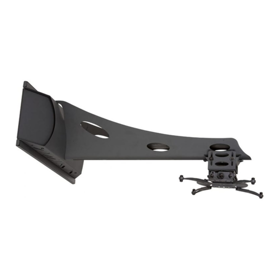
UNI-PDS/UNI-EPDS
Installation Guide
Installationsanleitung, Guía de Instalacíon, Guida de Installazione, Guide d'Installation, Installatie gids
Warranty, Garantie, Garantía, Garanzia, Garantie, Waarborg: http://www.mounts.com/warranty
9530-010-001-0X Rev.8
www.mounts.com | North America 800.368.9700 | International +1-714-632-7100 | Europe +44 (0) 24 7664 4105
1321 S. State College Blvd., Fullerton, CA 92831 USA
Advertisement
Table of Contents

Related Manuals for Premier Mounts UNI-PDS


Summary of Contents for Premier Mounts UNI-PDS
- Page 1 UNI-PDS/UNI-EPDS Installation Guide Installationsanleitung, Guía de Instalacíon, Guida de Installazione, Guide d’Installation, Installatie gids Warranty, Garantie, Garantía, Garanzia, Garantie, Waarborg: http://www.mounts.com/warranty 9530-010-001-0X Rev.8 www.mounts.com | North America 800.368.9700 | International +1-714-632-7100 | Europe +44 (0) 24 7664 4105 1321 S. State College Blvd., Fullerton, CA 92831 USA...
-
Page 2: Table Of Contents
THESE INSTALLATION INSTRUCTIONS IN AN EASILY ACCESSIBLE LOCATION FOR FUTURE REFERENCE. PREMIER MOUNTS DOES NOT WARRANT AGAINST DAMAGE CAUSED BY THE USE OF ANY PREMIER MOUNTS PRODUCT FOR PURPOSES OTHER THAN THOSE FOR WHICH IT WAS DESIGNED OR DAMAGE CAUSED BY UNAUTHORIZED ATTACHMENTS OR... -
Page 3: Installation Tools
Wrench Drill Parts List Make sure your Premier Mounts product has the following hardware and components before beginning installation. If there are parts missing and/or damaged, stop the installation and call Premier Mounts at (800) 368-9700. UNI-PDS/UNI-EPDS Hardware Extension Arm - Optional (Qty 1) -
Page 4: Pds-Plus-Sta/Pds-Plusw-Sta Mounting Hardware
M6 x 12mm Screw M6 x 12mm Security (Qty 8) Screw (Qty 8) ¼˝ - 20 x ˝ Screw ¼˝ - 20 x ˝ Security Screw (Qty 1) (Qty 1) Page 4 Visit the Premier Mounts website at http://www.mounts.com Installation Instructions... -
Page 5: Determining The Installation Height
Add 2.5˝ to the calculated total. Ground This total distance will be the location for the bottom rail on the wall plate. Proceed to the “Wood Stud Installation” section. Installation Instructions Visit the Premier Mounts website at http://www.mounts.com Page 5... -
Page 6: Wood Stud Installation
(2) lower mounting points. Wall Plate Step 4 Drill Marking Once the mounting points have been marked, use a ¼˝ drill bit and portable drill to drill the pilot holes. Page 6 Visit the Premier Mounts website at http://www.mounts.com Installation Instructions... -
Page 7: Attaching The Projector Arm
(please see Page 12). Mounting Hook Cutout MAKE SURE THE PROJECTOR ARM IS FULLY SEATED BEFORE RELEASING THE UNIT. Mounting Hooks Wall Plate Projector Arm Installation Instructions Visit the Premier Mounts website at http://www.mounts.com Page 7... -
Page 8: Throw Distance Calculation
Please make note of this measurement. Rear Lens Throw Distance = (X - Y + Z) The UNI-PDS/UNI-EPDS can be also used as a wall-mounted standard projector mount as Rear Lens well as a short throw projector mount. Align... -
Page 9: Adjustable Mounting Bracket Installation
±2˝. Once the Wrench desired height has been achieved, re-tighten the hardware. Do NOT overtighten these screws. Proceed to the “Attaching the Base Box to the Adjustable Mounting Bracket” section. Installation Instructions Visit the Premier Mounts website at http://www.mounts.com Page 9... -
Page 10: Attaching The Base Box To The Adjustable Mounting Bracket
Adjustable Mounting Bracket (above) for steps on M6 x 12 Security attaching the projector. Screw Security Wrench Extension Arm (Optional) Adjustable Mounting Bracket Proceed to the “Low Profile Bracket Installation” section. Page 10 Visit the Premier Mounts website at http://www.mounts.com Installation Instructions... -
Page 11: Low Profile Bracket Installation
Attach the projector to the base box, referring to the PDS-PLUS installation instructions for final adjustments. Proceed to the “Attaching the Universal Projector Plate” section. Security Wrench Base Box M6 x 12mm Screws Installation Instructions Visit the Premier Mounts website at http://www.mounts.com Page 11... -
Page 12: Attaching The Universal Projector Plate
If your projector has a single mount point, skip to the “Single Mount Point Installation” section. Small Straw Depth Plus 1/8” Allowance Small Straw Depth Plus 1/8” Allowance or Toothpick Mark or Toothpick Mark Page 12 Visit the Premier Mounts website at http://www.mounts.com Installation Instructions... - Page 13 (5) M3 flat washers inside the leveling barrel. Avoid stacking too many M3 washers; the mounting hardware must thread into the projector mount point at least four (4) complete turns. Installation Instructions Visit the Premier Mounts website at http://www.mounts.com Page 13...
- Page 14 Universal Projector Plate. If the M6 square nut is not aligned with any slot, you can use any thin implement, such as a toothpick, to nudge it into alignment. Page 14 Visit the Premier Mounts website at http://www.mounts.com Installation Instructions...
- Page 15 Do not overtighten the mounting screws. You can use either the standard Phillips head or Lock-It™ security hardware. Proceed to the “Attaching the Projector” section. Installation Instructions Visit the Premier Mounts website at http://www.mounts.com Page 15...
-
Page 16: Attaching The Projector
If your projector is not holding the tilt, install the four (4) external tooth washers on the four (4) M6 x 12mm Phillips head screws w/ Integrated Washers. Once all adjustments have been made, tighten all hardware. Page 16 Visit the Premier Mounts website at http://www.mounts.com Installation Instructions... -
Page 17: Set Screw Installation
Tighten using a security wrench. Repeat this process for the other side as well. Proceed to the “Cable Management” section. Electronic Components Door Security Wrench M5 x 8mm Security Screw Installation Instructions Visit the Premier Mounts website at http://www.mounts.com Page 17... -
Page 18: Cable Management
The cable access holes are located at the end of the short throw mount and on the wall plate. UNI-STA Route the cables through one end of the UNI-PDS/UNI-EPDS and out the other end. Electronic Attach the end cover with an M5 x 8mm security head screw. -
Page 19: Technical Specifications
UNI-PDS/UNI-EPDS Technical Specifications All measurements are in inches(mm). Installation Instructions Visit the Premier Mounts website at http://www.mounts.com Page 19... -
Page 20: Warranty
At the sole option of Premier Mounts, Premier Mounts will repair or replace any product or product part that is defective. If Premier Mounts chooses to replace a defective product or part, a replacement product or part will be shipped to you at no charge, but you must pay any labor costs.
Need help?
Do you have a question about the UNI-PDS and is the answer not in the manual?
Questions and answers