Advertisement
Available languages
Available languages
Quick Links
- Istruzioni per bruciatori modello
- Instruction for burners model
- Instrucciónes para quemadores modelos
- Mode d'emploi bruleûr
- Betriebsanleitung
Prima di iniziare a usare il bruciatore leggere attentamente
quanto esposto nel capitolo "AVVERTENZE PER
L ' U T E N T E , P E R L' U S O I N S I C U R E Z Z A D E L
BRUCIATORE" presente all'interno del manuale istruzioni,
che costituisce parte integrante ed essenziale del prodotto.
it
en
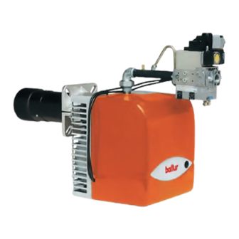
BTG 20 LX
Edizione / Edition / Edition
Ediciòn / Ausgabe
Cod. 0006080937
sp
fr
de
2004/11
Advertisement

Related Manuals for baltur BTG 20 LX


Summary of Contents for baltur BTG 20 LX
- Page 1 - Instruction for burners model - Instrucciónes para quemadores modelos - Mode d’emploi bruleûr - Betriebsanleitung BTG 20 LX Prima di iniziare a usare il bruciatore leggere attentamente Edizione / Edition / Edition 2004/11 quanto esposto nel capitolo “AVVERTENZE PER Ediciòn / Ausgabe...
- Page 2 IT - Leggere attentamente le istruzioni prima di mettere in funzione il bruciatore o di eseguire la manutenzione. - I lavori sul bruciatore e sull’impianto devono essere eseguiti solo da personale qualificato. - L’alimentazione elettrica dell’impianto deve essere disinserita prima di iniziare i lavori. - Se i lavori non sono eseguiti correttamente si rischiano incidenti pericolosi.
- Page 3 Normes CE – CEI – UNI en vigueur au moment de la fabrication. • La BALTUR garantit la certification “CE” seulement si les brûleur sont installé avec les rampes de gaz “CE” produites par la BALTUR et les accessoires de ligne gaz “CE” (fournis sur demande).
-
Page 4: Table Of Contents
ITALIANO ----------------------------------------------------------------------------------------------------------------------------------------------- 11 AVVERTENZE PER L’UTENTE PER L’USO IN SICUREZZA DEL BRUCIATORE -------------------------------------------------- 6 CARATTERISTICHE TECNICHE - CAMPO DI LAVORO ----------------------------------------------------------------------------------- 8 APPLICAZIONE DEL BRUCIATORE ALLA CALDAIA -------------------------------------------------------------------------------------- 11 DESCRIZIONE DEL FUNZIONAMENTO - COLEGAMENTI ELETTRICI -------------------------------------------------------------- 12 DESCRIZIONE FUNZIONAMENTO DELLA MODULAZIONE - ACCENSIONE E REGOLAZIONE A GAS METANO ---- 13 REGOLAZIONE DELL'ARIA SULLA TESTA DI COMBUSTIONE - REGOLAZIONE COMBUSTIONE ------------------------ 16 SCHEMA DISPOSIZIONE ELETTRODI - SCHEMA DI MONTAGGIO VENTOLA - USO DEL BRUCIATORE -------------- 18 MANUTENZIONE ------------------------------------------------------------------------------------------------------------------------------------- 19... -
Page 5: Table Of Contents
FRANÇAIS ---------------------------------------------------------------------------------------------------------------------------------------------- 56 APPLICATION DU BRULEUR A LA CHAUDIERE ------------------------------------------------------------------------------------------- 56 DESCRIPTION DU FONCTIONNEMENT - RACCORDEMENTS ELECTRIQUES ------------------------------------------------- 57 ALLUMAGE ET REGLAGE GAZ NATUREL - DESCRIPTION DU FONCTIONNEMENT DE LA MODULATION ----------- 58 REGLAGE DE L’AIR SUR LA TETE DE COMBUSTION - RÉGLAGE COMBUSTION - SCHEMA REGLAGE TETE DE COMBUSTION ---------------------------------------------------------------------------------------------- 62 MANUTENTION --------------------------------------------------------------------------------------------------------------------------------------- 64 Coffret de contrôle automatique pour brûleurs au gaz ------------------------------------------------------------------------------------- 65... - Page 6 Rivolgersi esclusivamente a personale professionalmente qualificato. L’eventuale riparazione dei prodotti dovrà essere effettuata solamente da un centro di assistenza autorizzato dalla BALTUR utilizzando esclusivamente ricambi originali. Il mancato rispetto di quanto sopra, può compromettere la sicurezza dell’apparecchio. Per garantire l’efficienza dell’ apparecchio e per il suo corretto funzionamento é indispensabile fare effettuare da personale professionalmente qualificato la manutenzione periodica attenendosi alle indicazioni del costruttore.
- Page 7 AVVERTENZE PER L’UTENTE PER L’USO IN SICUREZZA DEL BRUCIATORE ALIMENTAZIONE ELETTRICA • La sicurezza elettrica dell’apparecchio è raggiunta soltanto quando lo stesso è corretamente collegato a un’efficace impianto di messa a terra, eseguito come previsto dalle vigenti norme di sicurezza (D.P.R. 547/55 art. 314). E’ necessario verificare questo fondamentale requisito di sicurezza. In caso di dubbio, richiedere un controllo accurato dell’impianto elettrico da parte di personale professionalmentequalificato, poiché...
- Page 8 CARATTERISTICHE TECNICHE / TECHNICAL DATA / CARACTERISTIQUES TECHNIQUES / TECNISCHEN DATEN / CARACTERISTICAS TECNICAS / AUSSTATTUNG BTG 20 Lx PORTATA GAS NATURALE / NATURAL GAS FLOW RATE / CAUDAL GAS NATURAL / DEBIT GAZ NATUREL / DURCHSATZ ERDGAS MAX 20,6 PORTATA G.P.L.
- Page 9 CAMPO DI LAVORO / OPERATING FIELD / ARBEITSFELD / PLAGE DE FONCTIONNEMENT / CAMPO DE TRABAJO Posizione del diffusore X = min.(sinistra) e X = max.(destra) Position of air diffusor X = min. (left) and X = max. (right) Position der Stauscheibe X = min. (links) und X = max. (rechts) Position du diffuseur X = min.(gauche) et X = max.(droite) Campo di lavoro / Operating field / Arbeitsfeld / Plage de fonctionnement / Campo de trabajo...
- Page 10 CARATTERISTICHE TECNICHE / TECHNICAL N° 0002471010 SPECIFICATIONS / CARACTERISTIQUES TECHNIQUES / CARACTERISTICAS TECNICAS / Rev.20/10/2004 AUSSTATTUNG * Quota in versione CE Dimension for CE version Coutas de inversió CE Cote en version CE Apparecchiatura Control box Trasformatore Transformer Connettore 7 poli 7 pole connector 3.1) Connettore 4 poli 3.1) 4 pole connector...
-
Page 11: Applicazione Del Bruciatore Alla Caldaia
BRUCIATORI DI GAS BISTADIO PROGRESSIVO N° 0002934100 APPLICAZIONE DEL BRUCIATORE ALLA CALDAIA Rev. 10/02/2004 La tubazione di adduzione gas deve essere dimensionata in funzione della lunghezza e della erogazione di gas secondo norma UNI; deve essere perfettamente ermetica ed adeguatamente provata prima del collaudo del bruciatore. - Page 12 BRUCIATORI DI GAS BISTADIO PROGRESSIVO N° 0002934330 RILEVAZIONE PRESSIONE IN CAMERA DI COMBUSTIONE REV.:22/10/2004 Qualora il foro sul portellone sia di dimensioni insufficienti al passaggio del tubino e il portellone sia sprov- visto del vetrino ispezione fiamma, è necessario praticare un foro Ø 12 in corrispondenza del raccordo 1/4” dove installare il tubino prelievo pressione in camera di combustione (a corredo del bruciatore).
- Page 13 BRUCIATORI DI GAS BISTADIO PROGRESSIVO DESCRIZIONE FUNZIONAMENTO DELLA MODULAZIONE Quando il bruciatore è acceso alla portata minima, se la sonda di modulazione lo consente (regolata ad un valore di temperatura o pressione superiore a quella esistente in caldaia) il servomotore di regolazione aria inizia a girare determinando un aumento graduale dell’erogazione di aria di combustione e, di conseguenza del gas, fino a raggiungere l’erogazione massima cui il bruciatore è...
- Page 14 BRUCIATORI DI GAS BISTADIO PROGRESSIVO 6) Applicare un manometro con scala adeguata, alla presa di pressione del gas per rilevare il valore di regolazione (se l’entità della pressione prevista lo consente è preferibile utilizzare uno strumento a colonna d’acqua, non utilizzare per pressioni modeste strumenti a lancetta).
- Page 15 BRUCIATORI DI GAS BISTADIO PROGRESSIVO 13) Per variare l’erogazione massima della portata di gas si agisce sul regolatore della portata di aria perché la portata di gas si adegua, automaticamente, all’erogazione di aria. Occorre quindi operare sulla camma che regola la posizione di apertura massima della serranda dell’aria (vedi dis. n° 0002934320). Bisogna ridurre l’angolo di apertura della serranda dell’aria per ridurre la portata di gas e viceversa.
- Page 16 BRUCIATORI DI GAS BISTADIO PROGRESSIVO 22) Nel caso di fotocellula UV dopo almeno un minuto dall’avvenuta accensione, estrarre la fotocellula sfilandola dalla sua sede. Quando la fotocellula UV è sfilata dalla sua sede non può “vedere” la radiazione ultravioletta emessa dalla fiamma, pertanto il relativo relè si diseccita. Il bruciatore si arresta subito in “blocco”. Una leggera untuosità...
- Page 17 BRUCIATORI DI GAS BISTADIO PROGRESSIVO REGOLAZIONE COMBUSTIONE D VITE REGOLAZIONE DISCO FIAMMA E INDICE POSIZIONE DISCO FIAMMA (0 = MIN; 3 = MAX) N° 0002934171 SCHEMA REGOLAZIONE TESTA DI COMBUSTIONE REV.: 26/05/2004 Entrata gas Elettrodo accensione Flangia attacco caldaia X = Distanza testa/disco. NOTA: Diminuendo la distanza “X”...
- Page 18 BRUCIATORI DI GAS BISTADIO PROGRESSIVO N° 0002934181 SCHEMA DISPOSIZIONE ELETTRODI REV.:26/05/2004 Elettrodo ionizzatore Elettrodo accensione Disco fiamma BTG 20Lx Miscelatore 2÷3 Tubo mandata gas N° 0002934150 SCHEMA DI MONTAGGIO VENTOLA REV.:26/05/2004 Verificare in fase di montaggio ventola che sia rispettata la misura indicata in figura.
-
Page 19: Manutenzione
BRUCIATORI DI GAS BISTADIO PROGRESSIVO MANUTENZIONE Il bruciatore non ha bisogno di particolare manutenzione, sarà comunque bene controllare periodicamente che il filtro del gas sia pulito e l’elettrodo di ionizzazione efficiente. Occorre anche verificare che la scintilla dell’elettrodo di accensione avvenga esclusivamente tra tra lo stesso ed il disco di lamiera forata.Può anche rendersi necessa- ria la pulizia della testa di combustione. - Page 20 BRUCIATORI DI GAS BISTADIO PROGRESSIVO APPARECCHIATURA DI CAMANDO E CONTROLLO PER BRUCIATORI A GAS di piccola e media potenzialità, con o senza ventilatore (servizio intermittente*)
- Page 21 BRUCIATORI DI GAS BISTADIO PROGRESSIVO APPARECCHIATURA DI CAMANDO E CONTROLLO PER BRUCIATORI A GAS di piccola e media potenzialità, con o senza ventilatore (servizio intermittente*)
- Page 22 BRUCIATORI DI GAS BISTADIO PROGRESSIVO APPARECCHIATURA DI CAMANDO E CONTROLLO PER BRUCIATORI A GAS di piccola e media potenzialità, con o senza ventilatore (servizio intermittente*)
-
Page 23: Precisazioni Sull'uso Del Propano (G.p.l.)
BRUCIATORI DI GAS BISTADIO PROGRESSIVO PRECISAZIONI SULL’USO DEL PROPANO (G.P.L.) Riteniamo utile portare a Vostra conoscenza alcune considerazioni circa l’uso del gas liquido propano (G.P.L.). 1) Valutazione, indicativa, del costo di esercizio a) 1 m di gas liquido in fase gassosa ha un potere calorifico inferiore, di circa 22.000 kcal. b) Per ottenere 1 m di gas occorrono circa 2 kg di gas liquido che corrispondono a circa 4 litri di gas liquido. - Page 24 BRUCIATORI DI GAS BISTADIO PROGRESSIVO BT 8721/2 SCHEMA DI PRINCIPIO PER RIDUZIONE PRESSIONE GPL A DUE SALTI PER BRUCIATORE OPPURE CALDAIA REV. 26/05/2004 PRESSOSTATO ARIA Eseguire la regolazione del pressostato aria dopo aver effettuato tutte le altre regolazioni del bruciatore con il pressostato aria regolato a inizio scala. Con il bruciatore funzionante alla potenza richiesta, agire sulla vite centrale lenta- mente in senso orario fino al blocco del bruciatore.
-
Page 25: Irregolarità Di Funzionamento
BRUCIATORI DI GAS BISTADIO PROGRESSIVO IRREGOLARITÀ DI FUNZIONAMENTO IRREGOLARITÁ CAUSA POSSIBILE RIMEDIO L’apparecchio va in “blocco” con 1) Disturbo della corrente di Ionizzazio- 1) Invertire l’alimentazione (lato 230V) fiamma (lampada rossa accesa). ne da parte del trasformatore di accen- del trasformatore di accensione e Guasto circoscritto al dispositivo sione. -
Page 26: Installing On Boyler
TWO STAGE PROGRESSIVE NATURAL GAS BURNERS N° 0002934100 INSTALLING ON BOYLER Rev. 10/02/2004 The dimensions of the gas adduction pipeline should be in function with it’s length and with gas delivery according to UNI regulations; It must be perfectly hermetic and adequately tested before the burner is general inspection. It is indispensable to install a suitable pipe union in the pipeline, in proximity to the burner, to allow for easy disas- sembly of the burner and opening of the boiler door. -
Page 27: Electrical Connections
TWO STAGE PROGRESSIVE NATURAL GAS BURNERS N° 0002934330 MEASURING THE PRESSURE IN THE COMBUSTION CHAMBER REV.:22/10/2004 If the hole in the door is too small to allow the hose to pass and the door has no flame inspection window it will be necessary to make a Ø 12 hole at the site of the 1/4" connection for the insertion of the pressure take up hose in the combustion chamber (provided with the burner). - Page 28 TWO STAGE PROGRESSIVE NATURAL GAS BURNERS DESCRIPTION OF THE MODULATION OPERATION When the burner is on at the minimum flow rate, if the modulation sensor allows it (adjusted to a higher pressure or temperature value than that in the boiler), the air regulation servomotor start running, thus determining a gradual increase of the combustion air supply, and consequently, of gas, until the maximum supply at which the burner is regulated is reached.
- Page 29 TWO STAGE PROGRESSIVE NATURAL GAS BURNERS Regulate the air for the ignition flame, for minimum flame and high flame, following the instructions for regu- lating air damper control electrical motor shown in the following pages. In practice, set the low flame and high flame air regulation cams to the suitable positions according to the desired thermal power for low and high flame.
- Page 30 TWO STAGE PROGRESSIVE NATURAL GAS BURNERS 15) After adjusting the operation to the high flame (maximum) you must operate so that the air regulation servomotor sets to the minimum to perform the control also in this position. 16) To set the air – and thus gas – regulation servomotor to the minimum, set the modulation switch to MIN. 17) When the air servomotor is set to minimum, and it is necessary to change the combustion conditions (gas/air), see the instructions for regulating gas valves model MB-VEF...
- Page 31 TWO STAGE PROGRESSIVE NATURAL GAS BURNERS AIR REGULATION ON COMBUSTION HEAD Warning: When, as in this case, the burner is provided with gas valves model MB-VEF.., by moving the air regulation device on the combustion head there automatically and unavoidably occurs a gas output variation (see chapter Valve operation principle, model MB-VEF...).
- Page 32 TWO STAGE PROGRESSIVE NATURAL GAS BURNERS N° 0002934171 COMBUSTION HEAD ADJUSTMENT DIAGRAM REV.: 26/05/2004 Gas inlet Ignition electrode Burner fixing flange X = Disk / head distance NOTE: if the distance X is reduced the NOx emissions value falls. Always adjust the distance X between the minimum and maximum valuesspecified in the work field.
- Page 33 TWO STAGE PROGRESSIVE NATURAL GAS BURNERS N° 0002934150 FAN ASSEMBLY DIAGRAM Rev. 07/04/2004 - Observe the measurements indicated in the diagram when fitting the fan. USE OF THE BURNER The burner operates fully automatically, therefore it is non necessary to carry out any kind at adjustment during its operating.
-
Page 34: Maintenance
TWO STAGE PROGRESSIVE NATURAL GAS BURNERS MAINTENANCE The burner does not require special maintenance, but it is good practice to check periodically that the gas filter is clean and that the ignition electrode is efficient. It is also necessary to verify that the ignition electrode’s spark is produced between the same electrode and the disk. - Page 35 TWO STAGE PROGRESSIVE NATURAL GAS BURNERS LMG 2..CONTROL BOX SPECIFICATIONS...
- Page 36 TWO STAGE PROGRESSIVE NATURAL GAS BURNERS LMG 2..CONTROL BOX SPECIFICATIONS...
- Page 37 TWO STAGE PROGRESSIVE NATURAL GAS BURNERS LMG 2..CONTROL BOX SPECIFICATIONS...
-
Page 38: Notes On Use Of Propane (L.p.g.)
TWO STAGE PROGRESSIVE NATURAL GAS BURNERS NOTES ON USE OF PROPANE (L.P.G.) We think it would be useful to inform you on a few points regarding use of liquid propane gas (L.P.G.). 1) Approximate evaluation of running costs a) 1 m of liquid gas in gaseous state has heating power inferior by about 22.000 kcal. - Page 39 TWO STAGE PROGRESSIVE NATURAL GAS BURNERS N° 8721/2/GB GENERAL DIAGRAM FOR TWO-STAGE L.P.G. PRESSURE REDUCTION FOR BURNER OR BOILER Rev. 21/03/90 AIR PRESSURE SWITCH Regulate the air pressure switch after first carrying out all the other burner adjustments with the air pressure switch adjusted to the start of the scale. With the burner operating at the requested power level, slowly turn the central screw clockwise until the burner locks out.
-
Page 40: Operating Anomaly
TWO STAGE PROGRESSIVE NATURAL GAS BURNERS OPERATING ANOMALY POSSIBLE CAUSE DETAILS OF PROBLEM SOLUTION 1) Disturbance to ionization The apparatus goes into “lock- 1) Invert the ignition transformer current from ignition out” with the flame (red light power supply (230V side) and transformer. -
Page 41: Aplicación Del Quemador A La Caldera
QUEMADORES DE GAS NATURAL DE DOS ETAPAS PROGRESIVO APLICACIÓN DEL QUEMADOR A LA CALDERA La tubería de abastecimiento del gas tiene que estar dimensionada en función de la longitud y del suministro del gas según la norma UNI; y tiene que ser totalmente hermética y haber sido probada antes de la prueba de ensayo del quemador. - Page 42 QUEMADORES DE GAS NATURAL DE DOS ETAPAS PROGRESIVO N° 0002934330 PRESIÓN DE LA CÁMARA DE COMBUSTIÓN REV.:22/10/2004 si el orificio de la puerta es demasiado pequeño para que pase el tubo y la puerta no tiene mirilla para la inspección de la llama hay que hacer un orificio de Ø 12 que corresponda con el racor 1/4" donde se instalará...
- Page 43 QUEMADORES DE GAS NATURAL DE DOS ETAPAS PROGRESIVO FUNCIONAMIENTO DE LA MODULACIÓN Si el quemador está encendido al mínimo y la sonda de modulación (regulada con una temperatura o una presión mayores que las de la caldera) lo permite, el servomotor que regula el aire comburente aumenta gradualmente el suministro hasta el máximo programado.
- Page 44 QUEMADORES DE GAS NATURAL DE DOS ETAPAS PROGRESIVO Nota : durante la preventilación con aire limpio el servomotor se activa y abre la compuerta hasta el máximo. Cuando el servomotor vuelve a la posición de “encendido” el sistema de mando activa el transformador y las válvulas del gas.
- Page 45 QUEMADORES DE GAS NATURAL DE DOS ETAPAS PROGRESIVO 21) Los presostatos del gas (mínima y máxima) bloquean el quemador cuando la presión no está comprendida entre los límites. El presostato que controla la presión mínima cierra su contacto cuando detecta una presión menor;...
- Page 46 QUEMADORES DE GAS NATURAL DE DOS ETAPAS PROGRESIVO N° 0002934171 REGULACIÓN DEL CABEZAL DE COMBUSTIÓN REV.: 26/05/2004 Entrada del gas Electrodo de encendido Arandela de conexión a la caldera X = Distanciacabezal/disco NOTA: Disminuyendo la distancia “X” disminuye el valor de emisión de NOx. Regular la distancia “X” siempre entre el valor mínimo (5mm) y máximo (13mm) especificado en el campo de trabajo.
- Page 47 QUEMADORES DE GAS NATURAL DE DOS ETAPAS PROGRESIVO N° 0002934150 ESQUEMA DE MONTAJE DEL VENTILADOR REV.:07/04/2004 Verificar durante la fase de montaje del ventilador que se respete la medida indicada en la figura. USO DEL QUEMADOR El quemador tiene un funcionamiento completamente automático y por ello no hacen falta maniobras de regulación durante su funcionamiento.
-
Page 48: Mantenimiento
QUEMADORES DE GAS NATURAL DE DOS ETAPAS PROGRESIVO MANTENIMIENTO El quemador no necesita un mantenimiento especial, pero es aconsejable que se controle periódicamente que el filtro del gas esté limpio y que el electrodo de ionización sea eficiente. Hay que verificar también que la chispa del electrodo de encendido se dé... - Page 49 QUEMADORES DE GAS NATURAL DE DOS ETAPAS PROGRESIVO...
- Page 50 QUEMADORES DE GAS NATURAL DE DOS ETAPAS PROGRESIVO...
- Page 51 QUEMADORES DE GAS NATURAL DE DOS ETAPAS PROGRESIVO...
- Page 52 QUEMADORES DE GAS NATURAL DE DOS ETAPAS PROGRESIVO...
-
Page 53: Puntualizaciones Sobre El Uso Del Propano (G.l.p.)
QUEMADORES DE GAS NATURAL DE DOS ETAPAS PROGRESIVO PUNTUALIZACIONES SOBRE EL USO DEL PROPANO (G.L.P.) Según nuestra opinión es útil poner en su conocimiento algunas consideraciones acerca del uso del gas líquido propano (G.L.P.). 1) ESTIMACIÓN INDICATIVA DEL COSTE DE UTILIZACIÓN a) 1 m de gas líquido en fase gaseosa tiene un poder calorífico inferior de 22.000 kcal aproximadamente. - Page 54 QUEMADORES DE GAS NATURAL DE DOS ETAPAS PROGRESIVO N° BT 8721/2 ESQUEMA DE PRINCIPIO PARA REDUCIR LA PRESIÓN G.L.P. CON DOS SALTOS PARA QUEMADOR O PARA CALDERA Rev. 21/03/90 PRESOSTATO DEL AIRE Regular el presostato del aire tras haber realizado las demás regulaciones del quemador con el presostato del aire regulado al inicio de la escala.
-
Page 55: Irregularidades En El Funcionamiento
QUEMADORES DE GAS NATURAL DE DOS ETAPAS PROGRESIVO IRREGULARIDADES EN EL FUNCIONAMIENTO ANOMALÍA CAUSA POSIBLE SOLUCIÓN Llama encendida, 1) El transformador de encendido 1) Invertir la alimentación (230 V) del el aparato se bloquea (testigo interfiere con la corriente de transformador de encendido y medir rojo encendido). -
Page 56: Application Du Bruleur A La Chaudiere
BRÛLEUR GAZ NATUREL DEUX ALLURES PROGRESSIVES N° 0002934100 APPLICATION DU BRULEUR A LA CHAUDIERE Rev. 10/02/2004 Le tuyau d’adduction gaz doit être de dimension adaptée à la longueur et à la distribution du gaz selon la norme UNI, il doit être parfaitement hermétique et testé avant la certification de bon fonctionnement du brûleur. Sur ce tuyau, il est indispensable d’installer, à... - Page 57 BRÛLEUR GAZ NATUREL DEUX ALLURES PROGRESSIVES CONTROLE DE LA PRESSION DANS LA CHAMBRE DE N° 0002934330 COMBUSTION REV.:22/10/2004 Si l’orifice situé sur la porte est de dimensions insuffisantes pour le passage du tuyau et si la porte n’est pas équipée de vitre d’inspection flamme, il est nécessaire de pratiquer un orifice de Ø 12 en face du raccord 1/4"...
- Page 58 BRÛLEUR GAZ NATUREL DEUX ALLURES PROGRESSIVES DESCRIPTION DU FONCTIONNEMENT DE LA MODULATION Lorsque le brûleur est allumé au débit minimum, si la sonde de modulation le permet (réglée à une valeur de température ou de pression inférieure à celle existante en chaudière), le servomoteur de réglage de l’air commence à...
- Page 59 BRÛLEUR GAZ NATUREL DEUX ALLURES PROGRESSIVES 7) Régler l’air pour la flamme d’allumage, la petite et la grande flamme en respectant les instructions de réglage du moteur électrique de commande du volet d’air indiquées aux pages suivantes. En pratique, porter les cames de réglage de l’air de la petite et de la grande flamme dans les positions jugées adaptées en fonction des puissances thermiques désirées pour la petite et la grande flamme.
- Page 60 BRÛLEUR GAZ NATUREL DEUX ALLURES PROGRESSIVES 14) Ensuite, contrôler la combustion à l’aide des instruments appropriés et modifier, si nécessaire, le réglage existant (air et, éventuellement, gaz). A l’aide des instruments appropriés, il est indispensable de vérifier que le pourcentage d’oxyde de carbone (CO) présent dans les fumées ne dépasse pas la valeur maximale admise de 0,1 % et que le CO ne dépasse pas 10% pour le méthane.
- Page 61 BRÛLEUR GAZ NATUREL DEUX ALLURES PROGRESSIVES 22) Dans le cas de la photolecture UV, au moins une minute après l’allumage, extraire la photocellule en la retirant de son logement. Lorsque la photocellule UV est retirée de son logement, elle ne peut plus «voir» la radiation ultraviolette émise par la flamme, par conséquent, le relais correspondant se désexcite.
- Page 62 BRÛLEUR GAZ NATUREL DEUX ALLURES PROGRESSIVES RÉGLAGE COMBUSTION D VIS DE REGLAGE DEFLECTEUR E INDEX POSITION DEFLECTEUR (0 = MIN; 3 = MAX) N° 0002934171 SCHEMA REGLAGE TETE DE COMBUSTION REV.: 26/05/2004 Arrivée de gaz Electrode d’allumage Bride de fixation chaudière X = Distance tête/disque REMARQUE: En diminuant la distance “X”, la valeur d’émission de NOx diminue.
- Page 63 BRÛLEUR GAZ NATUREL DEUX ALLURES PROGRESSIVES N° 0002934181 SCHEMA DISPOSITION DES ELECTRODES REV.:26/05/2004 Electrode d’ionisation Electrode d’allumage Disque flamme BTG 20Lx Mélangeur 2÷3 Tuyau de départ gaz N° 0002934150 N° 0002934150 N° 0002934150 SCHEMA DE MONTAGE VENTILATEUR Rev. 07/04/2004 Rev. 07/04/2004 Rev.
-
Page 64: Manutention
BRÛLEUR GAZ NATUREL DEUX ALLURES PROGRESSIVES MANUTENTION Le brûleur ne nécessite pas d’entretien particulier, dans tous les cas, il convient de contrôler périodiquement que le filtre soit propre et l’électrode de ionisation en bon état. Il est aussi nécessaire que l’étincelle de l’électrode d’allumage ait lieu exclusivement entre celle-ci et le disque de tôle perforée. - Page 65 BRÛLEUR GAZ NATUREL DEUX ALLURES PROGRESSIVES...
- Page 66 BRÛLEUR GAZ NATUREL DEUX ALLURES PROGRESSIVES...
- Page 67 BRÛLEUR GAZ NATUREL DEUX ALLURES PROGRESSIVES...
-
Page 68: Precisions Concernant L'utilisation Du Propane (G.p.l.)
BRÛLEUR GAZ NATUREL DEUX ALLURES PROGRESSIVES PRECISIONS CONCERNANT L’UTILISATION DU PROPANE (G.P.L.) Vous trouverez ci-après quelques remarques utiles concernant l’utilisation du gaz liquide propane (G.P.L.). 1) EVALUATION INDICATIVE DU COUT DE FONCTIONNEMENT a) 1 m de gaz liquide en phase gazeuse a un pouvoir calorifique inférieur d’environ 22.000 kcal. b) Pour obtenir 1 m de gaz, environ 2 kg de gaz liquide sont nécessaires, ce qui correspond à... -
Page 69: Schema De Principe Pour Reduction De Pression G.p.l. A Deux Ressauts
BRÛLEUR GAZ NATUREL DEUX ALLURES PROGRESSIVES BT 8721/2 SCHEMA DE PRINCIPE POUR REDUCTION DE PRESSION G.P.L. A DEUX RESSAUTS POUR BRULEUR OU CHAUDIERE 21/03/90 PRESSOSTAT D’AIR Effectuer le réglage du pressostat d’air après avoir effectué tous les autres réglages du brûleur avec le pressostat d’air réglé en début d’échelle. Lorsque le brûleur fonctionne à... -
Page 70: Irrégularités De Fonctionnement
BRÛLEUR GAZ NATUREL DEUX ALLURES PROGRESSIVES IRRÉGULARITÉS DE FONCTIONNEMENT IRRÉGULARITÉ CAUSE ÉVENTUELLE REMÈDE L’appareil va en position de 1) perturbation du courant d’ionisation 1) Invertir l’alimentation (côté 230V) de la part du transformateur du transformateur d’allumage et “ blocage ” avec flamme d’allumage vérifier à... -
Page 71: Anbringung Des Brenners Am Heizkessel
ZWEISTUFIG GLEITEND BEI ERDGAS BRENNER N° 0002934100 ANBRINGUNG DES BRENNERS AM HEIZKESSEL Rev. 10/02/2004 Die Gaszuführungsleitung muss in Abhängigkeit von der Länge und der Gaszufuhr nach UNI-Norm dimensioniert, absolut dicht und vor der Abnahme des Brenners in geeigneter Weise überprüft sein. An dieser Leitung muss unbedingt in der Nähe des Brenners ein geeigneter Anschluss für ein leichtes Abbauen des Brenners und/oder zur bequemen Öffnung der Heizkesselklappe eingebaut werden. - Page 72 ZWEISTUFIG GLEITEND BEI ERDGAS BRENNER N° 0002934330 ERMITTLUNG BRENNKAMMERDRUCK REV.:22/10/2004 Falls die Öffnung in der Klappe nicht groß genug ist, um das Röhrchen durchzuführen, und auch kein Inspektionsfenster für die Flamme hat, muss auf Höhe des Anschlusses 1/4" ein Loch von Ø 12 gebohrt werden, in dem das Röhrchen für die Druckmessung (mit dem Brenner mitgeliefert) zu installieren ist.
- Page 73 ZWEISTUFIG GLEITEND BEI ERDGAS BRENNER BESCHREIBUNG DER MODULIERENDEN FUNKTIONSWEISE Wenn der Brenner mit Mindestdurchsatz läuft und die Modulationssonde (die auf einen höheren Temperatur- oder Druckwert als den im Heizkessel vorhandenen eingestellt ist) es zulässt, beginnt der Stellmotor für Luftregulierung zu drehen und bewirkt damit eine allmähliche Erhöhung der Verbrennungsluft- und folglich der Gaszufuhr, bis die maximale Zufuhr, auf die der Brenner eingestellt ist, erreicht wird.
- Page 74 ZWEISTUFIG GLEITEND BEI ERDGAS BRENNER Ein Manometer mit geeigneter Skala an den Gasdruckabgriff anschließen, um den Einstellwert zu ermitteln (soweit der vorgesehene Druckwert es erlaubt, ist es besser, ein Instrument mit Wassersäule zu benutzen, für mäßige Drücke keine Zeigerinstrumente verwenden). Die Luft für die Zündflamme, die kleinste und die große Flamme einstellen und sich dabei an die Anleitungen für die Einstellung des Elektromotors der Luftklappe auf den folgenden Seiten halten.
- Page 75 ZWEISTUFIG GLEITEND BEI ERDGAS BRENNER 13) Zum Ändern des maximalen Gasdurchsatzes den Luftdurchsatzregler betätigen, weil sich der Gasdurchsatz automatisch an die Luftzufuhr anpasst. Es muss also der Nocken, der die maximale Öffnungsposition der Luftklappe regelt, verstellt werden (siehe Zch. Nr. 0002934320). Um den Gasdurchsatz zu vermindern, muss der Öffnungswinkel der Luftklappe verkleinert werden und umgekehrt.
-
Page 76: Lufteinstellung Am Brennerkopf
ZWEISTUFIG GLEITEND BEI ERDGAS BRENNER Wenn die UV-Fotozelle mindestens eine Minute nach erfolgter Zündung anspricht, die Fotozelle heraus- nehmen. Wenn die UV-Fotozelle herausgenommen ist, kann sie nicht mehr die von der Flamme abgegebene Ultraviolettstrahlung “sehen”, daher erregt sich das zugehörige Relais ab. Der Brenner geht sofort auf “Sperre”. - Page 77 ZWEISTUFIG GLEITEND BEI ERDGAS BRENNER EINSTELLUNG VERBRENNUNG D STELLSCHRAUBE STAUSCHEIBE E POSITIONSZEIGER STAUSCHEIBE (0 = MIN; 3 = MAX) N° 0002934171 EINSTELLUNGSPLAN BRENNERKOPF REV.: 26/05/2004 Gaseingang Zündelektrode Anschlussflansch Heizkessel X = Abstand Kopf-Scheibe HINWEIS: Bei Verringerung des Abstands “X” wird der NOx-Ausstoß vermindert. Den Abstand “X” immer zwischen dem im Arbeitsfeld angegebenen Mindest- und Höchstwert einstellen.
- Page 78 ZWEISTUFIG GLEITEND BEI ERDGAS BRENNER N° 0002934181 ELEKTRODENLAGEPLAN REV.:26/05/2004 Ionisationselektrode Zündelektrode Stauscheibe BTG 20Lx Mischer 2÷3 Gasrohr N° 0002934150 MONTAGEPLAN GEBLÄSE REV.:26/05/2004 Bei der Montage des Gebläses kontrollieren, ob das in der Abbildung angegebene Maß eingehalten wird. BENUTZUNG DES BRENNERS Der Brenner funktioniert vollautomatisch, daher sind während des Betriebs keine Einstellvorgänge erforderlich.
-
Page 79: Wartung
ZWEISTUFIG GLEITEND BEI ERDGAS BRENNER WARTUNG Der Brenner benötigt keine besondere Wartung, es ist jedoch gut, in Abständen zu überprüfen, ob der Gasfilter sauber und die Ionisationselektrode funktionstüchtig ist. Es muss auch überprüft werden, ob der Funke der Zündelektrode ausschließlich zwischen dieser und der Lochblechscheibe überspringt. Es kann auch eine Reinigung des Brennerkopfs erforderlich werden. - Page 80 ZWEISTUFIG GLEITEND BEI ERDGAS BRENNER...
- Page 81 ZWEISTUFIG GLEITEND BEI ERDGAS BRENNER...
- Page 82 ZWEISTUFIG GLEITEND BEI ERDGAS BRENNER...
-
Page 83: Angaben Zum Gebrauch Von Propan (Flüssiggas)
ZWEISTUFIG GLEITEND BEI ERDGAS BRENNER ANGABEN ZUM GEBRAUCH VON PROPAN (FLÜSSIGGAS) Wir möchten Ihnen hier gerne ein paar nützliche Hinweise für den Umgang mit Flüssiggas (G.P.L.) geben. 1) INDIKATIVE BERECHNUNG DER BETRIEBSKOSTEN Flüssiggas in gasförmiger Phase hat eine niedrigere Wärmeleistung, von ca. 22.000 Kcal. Für 1 m Gas braucht man ca. - Page 84 ZWEISTUFIG GLEITEND BEI ERDGAS BRENNER N° BT 8721/2 GROBSCHEMA FÜR DIE DRUCKVERMINDERUNG VON FLÜSSIGGAS IN ZWEI STUFEN FÜR BRENNER ODER FÜR HEIZKESSEL Rev. 21/03/90 LUFTDRUCKWÄCHTER Die Einstellung des Luftdruckwächters vornehmen, nachdem alle anderen Einstellungen des Brenners mit Luftdruckwächter auf Skalennullpunkt durchgeführt wurden.
-
Page 85: Betriebsstörungen
ZWEISTUFIG GLEITEND BEI ERDGAS BRENNER BETRIEBSSTÖRUNGEN STÖRUNG (irregolarità) MÖGLICHE URSACHE ABHILFE Das Gerät geht bei Flamme auf 1) Störung des Ionisationstroms durch 1) Die Spannungsversorgung (Seite “Sperre” (rote Lampe ein). den Zündtransformator. 230V) des Zündtransfor-mator ver- tauschen und mit Analog-Mikro- Flammenkontrollvorrichtung amperemeter überprüfen. -
Page 86: Anleitung Blockventil Mit Fortlaufender Modulation
BRUCIATORI DI GAS BISTADIO PROGRESSIVO N° 0002910620 DUNGS mod. MB-VEF BO1 Rev. 05/06/00 ISTRUZIONI VALVOLA MONOBLOCCO CON FUNZIONAMENTO A MODULAZIONE CONTINUA INSTRUCTIONS FOR MONOBLOC VALVE WITH CONTINUOUS MODULATION OPERATION INSTRUCCIONES SOBRE LA VÁLVULA MONOBLOQUE CON FUNCIONAMIENTO CON MODULACIÓN CONTINUA INSTRUCTIONS VANNE MONOBLOC AVEC FONCTIONNEMENT A MODULATION CONTINUE ANLEITUNG BLOCKVENTIL MIT FORTLAUFENDER MODULATION Allacciamento elettrico pressostato (DIN 43650) Allacciamento elettrico valvole (DIN 43650) - Page 87 BRUCIATORI DI GAS BISTADIO PROGRESSIVO N° 0002910620 DUNGS mod. MB-VEF BO1 Rev. 05/06/00 Conexión eléctrica Puesta a tierra conforme a las normas locales Tomas de presión 1,3,4,6 Tapón con tornillo G 1/8 Toma para medir la presión Tapón con tornillo M4 7,8,9 Rosca interna G 1/8 para los tubos medición impulsos de presión P...
- Page 88 BRUCIATORI DI GAS BISTADIO PROGRESSIVO N° 0002910620 DUNGS mod. MB-VEF BO1 Rev. 05/06/00 Instalación de los tubos de medición impulsos de presión : presión del gas en la entrada S10: 5-100 mbar S30: 100-360 mbar : presión en el soplador, aire 0,4 -100 mbar : presión en la caldera - 2 mbar …...
- Page 89 BRUCIATORI DI GAS BISTADIO PROGRESSIVO N° 0002910620 DUNGS mod. MB-VEF BO1 Rev. 05/06/00 Taratura del gruppo regolazione-pressione Il gruppo regolazione- pressione viene pre-tarato in fabbrica. I valori di taratura devono essere poi adattati sul posto alle esigenze dell‘ impianto. La valvola modulante mod. MB-VEF B01 opera aumentando automaticamente l’erogazione del gas se aumenta l’erogazione dell’aria, e riduce automaticamente l’erogazione del gas se viene ridotta l’erogazione dell’aria.
- Page 90 BRUCIATORI DI GAS BISTADIO PROGRESSIVO Setting the pressure – adjustment unit TARADO DEL GRUPO DE REGULACIÓN - PRESIÓN El grupo de regulación - presión se tara previamente The pressure – adjustment unit is factory set. en la fábrica. En un segundo momento, los valores Settings should then be adapted on site to suit de tarado tienen que ser adaptados a las exigencias the needs of the system.
- Page 91 BRUCIATORI DI GAS BISTADIO PROGRESSIVO TARAGE DU GROUPE DE RÉGLAGE – PRESSION KALIBRIERUNG DER GRUPPE DRUCKEINSTELLUNG Le groupe de réglage – pression est préréglé en usine. Ensuite, les valeurs de tarage doivent être adaptées sur place en fonction Die Gruppe Druckeinstellung wir im Werk vorkalibriert. des exigences de l‘installation.
- Page 92 BRUCIATORI DI GAS BISTADIO PROGRESSIVO max/maxi = 100 mbar V max/maxi = 3:1 min./mini min./mini = 0,4 mbar V min./mini = 0,75:1 max/maxi Nullpunkorrektur ± 1 mbar max/maxi = 100 mbar Zero point adjustement ± 1 mbar min./mini = 0,5 mbar Correction point zéro ±...
- Page 93 BRUCIATORI DI GAS BISTADIO PROGRESSIVO REGOLAZIONE CAMME SERVOMOTORE / CAMS REGULATION N° 0002934320 SERVOMOTOR / NOCKEN REGELUNG STELLMOTOR / REGULATION REV.:15/10/2004 CAMES SERVOMOTEUR / REGLAJE LEVAS SERVOMOTOR SQN70.624A20 CAMME REGOLABILI PERNO DI INSERZIONE ED ESCLUSIONE ACCOPPIAMENTO MOTORE-ALBERO CAMME. ADJUSTABLE CAMS INSERTION AND DISINSERTION LEVER MOTOR CONNECTION CAMSHAFT.
-
Page 94: Anlagenplan Mit Verdunster
SCHEMA D’IMPIANTO CON VAPORIZZATORE / LAYOUT DIAGRAM WITH VAPORISATION / SCHEMA D’INSTALLATION AVEC VAPORISATEUR / ANLAGENPLAN MIT VERDUNSTER / ESQUEMA DE LA INSTALACIÓN CON VAPORIZADOR eventuale collegamento fase gas di emergenza vaporizzatore / vaporizer / vaporisateur / eventual emergency gas phase connection verdunster/ vaporizador eventuel branchement d’urgence à... - Page 96 Technical data in this brochure are given as information only. Baltur reserves the right to change specification, without notice. El presente catàlogo tiene caràcter puramente indicativo. La Casa, por lo tanto, se reserva cualquier posibilitad de modificatiòn de datos técnicos y otras anotaciones.
Need help?
Do you have a question about the BTG 20 LX and is the answer not in the manual?
Questions and answers