Table of Contents
Advertisement
Available languages
Available languages
Advertisement
Chapters
Table of Contents

Related Manuals for baltur BTG 15


Summary of Contents for baltur BTG 15
- Page 1 BRUCIATORI DI GAS MONOSTADIO SINGLE-STAGE GAS BURNERS ITALIANO BTG 15 Manuale istruzioni per l'installazione, l'uso e la manutenzione BTG 20 Instruction manual for installation, use and maintenance BTG 28 ISTRUZIONI ORIGINALI (IT) ORIGINAL INSTRUCTIONS (IT) 0006080876_201912...
-
Page 3: Table Of Contents
ITALIANO ITALIANO SOMMARIO Avvertenze per l'uso in condizioni di sicurezza ..............................2 Caratteristiche tecniche ......................................5 Materiale a corredo ......................................6 Targa identificazione bruciatore..................................6 Dati registrazione prima accensione ................................6 Campo di lavoro .......................................7 Dimensioni di ingombro ....................................8 Descrizione componenti ....................................9 Caratteristiche tecnico funzionali ..................................10 Applicazione del bruciatore alla caldaia ................................ -
Page 4: Avvertenze Per L'uso In Condizioni Di Sicurezza
ITALIANO AVVERTENZE PER L'USO IN CONDIZIONI DI • L'apparecchio non è adatto a essere usato da persone (bambini compresi) le cui capacità fisiche, sensoriali o mentali siano ridotte, SICUREZZA oppure con mancanza di esperienza o di conoscenza. • l'uso dell'apparecchio è consentito a tali persone solo nel caso in SCOPO DEL MANUALE cui possano beneficiare, attraverso l'intermediazione di una perso- Il manuale si propone di contribuire all'utilizzo sicuro del prodotto a... - Page 5 • Prima di avviare il bruciatore e almeno una volta all’anno, far ef- • L’eventuale riparazione dei prodotti dovrà essere effettuata sola- fettuare da personale professionalmente qualificato le seguenti mente da un centro di assistenza autorizzato da BALTUR o dal suo operazioni: distributore locale, utilizzando esclusivamente ricambi originali.
- Page 6 ITALIANO Avvertenze particolari per l’uso del gas. - Allorché si decida di non utilizzare l’apparecchio per un certo • Verificare che la linea di adduzione e la rampa siano conformi alle periodo é opportuno spegnere l’interruttore elettrico di alimen- norme e prescrizioni vigenti. tazione a tutti i componenti dell’impianto che utilizzano energia •...
-
Page 7: Caratteristiche Tecniche
ITALIANO CARATTERISTICHE TECNICHE MODELLO BTG 15 BTG 20 BTG 28 PIN omologazione CE0085BQ0476 CE0085BQ0476 CE0085BQ0476 Potenza termica massima metano Potenza termica minima metano mg/kWh ¹) emissioni metano Classe 2 Classe 3 Classe 2 Funzionamento Monostadio Monostadio Monostadio Trasformatore metano 50 hz... -
Page 8: Materiale A Corredo
ITALIANO MATERIALE A CORREDO MODELLO BTG 15 BTG 20 BTG 28 Flangia attacco bruciatore Guarnizione flangia attacco bruciatore Cordone isolante Prigionieri N°4 - M10 x 50 N°4 - M10 x 50 N°4 - M10 x 50 Dadi esagonali N°4 - M10 N°4 - M10... -
Page 9: Campo Di Lavoro
ITALIANO CAMPO DI LAVORO BTG20 BTG15 BTG28 mbar / hPa 60 70 80 90 100 110 120 130 140 150 160 170 180 190 200 210 220 230 240 250 260 270 280 290 300 n/h (Metano) 10 11 12 13 14 15 16 17 18 19 20 21 22 23 24 25 26 27 28 29 30 n/h (GPL) 10.5 11.5... -
Page 10: Dimensioni Di Ingombro
ITALIANO DIMENSIONI DI INGOMBRO EØ FØ 45° 45° Modello BTG 15 BTG 20 BTG 28 Modello E Ø F Ø LØ N Ø BTG 15 150 ÷ 280 170 ÷ 210 BTG 20 150 ÷ 300 170 ÷ 210 BTG 28 150 ÷... -
Page 11: Descrizione Componenti
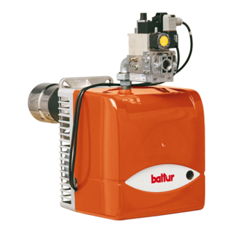
ITALIANO DESCRIZIONE COMPONENTI Apparecchiatura Trasformatore d'accensione Connettore 7 poli Vite di regolazione apertura serranda aria Riferimento disposizione disco - testa Testa di combustione Vite regolazione disco testa Motore Pressostato aria Guarnizione isolante Flangia attacco bruciatore Valvola gas monoblocco Pressostato gas 9 / 32 0006080876_201912... -
Page 12: Caratteristiche Tecnico Funzionali
ITALIANO CARATTERISTICHE TECNICO FUNZIONALI • Possibilità di ottenere ottimi valori di combustione tramite la regola- zione dell'aria comburente e della testa di combustione. • Testa di combustione a ricircolo parziale dei gas combusti ad emis- sioni ridotte di NOx (classe III). •... -
Page 13: Applicazione Del Bruciatore Alla Caldaia
ITALIANO APPLICAZIONE DEL BRUCIATORE ALLA CAUTELA / AVVERTENZE CALDAIA Accertarsi che la testa di combustione abbia lunghezza suf- ficiente per penetrare nel focolare nella quantità richiesta dal Bloccare la flangia (19) sul cannotto del bruciatore tramite la vite (8) costruttore della caldaia. e il dado (9)in dotazione (n°... - Page 14 ITALIANO La valvola gas DUNGS mod. MB... incorpora filtro e stabilizzatore della pressione gas, pertanto sulla tubazione di adduzione del gas, deve essere installato solo il rubinetto di intercettazione e giunto an- tivibrante. Solo nel caso in cui la pressione del gas fosse superiore al valore massimo ammesso delle Norme (400 mm.C.A.) occorre installare, sulla tubazione del gas, all’esterno della centrale termica un adatto riduttore di pressione.
-
Page 15: Collegamenti Elettrici
ITALIANO COLLEGAMENTI ELETTRICI • Tutti i collegamenti devono essere eseguiti con filo elettrico fles- sibile. • La sezione minima dei conduttori deve essere di 1.5 mm². • Le linee elettriche devono essere distanziate dalle parti calde. • L’installazione del bruciatore è consentita solo in ambienti con gra- do di inquinamento 2 come indicato nell’allegato M della norma EN 60335-1:2008-07. -
Page 16: Descrizione Del Funzionamento
ITALIANO DESCRIZIONE DEL FUNZIONAMENTO Il bruciatore è a funzionamento completamente automatico quindi non occorrono manovre di regolazione durante il suo funzionamento. La posizione di “blocco” è una posizione di sicurezza in cui il bruciato- re si porta automaticamente, quando qualche particolare del brucia- tore o dell’impianto è... -
Page 17: Accensione E Regolazione
ITALIANO ACCENSIONE E REGOLAZIONE • Con bruciatore acceso adeguare l’erogazione al valore desiderato per la “prima fiamma” effettuando la lettura al contatore. Con bruciatore trifase, verificare che il senso di rotazione del motore • La portata può essere modificata agendo sull’apposito regolatore sia corretto. -
Page 18: Regolazione Aria Sulla Testa Di Combustione
1/2 giro. 13 - Indice di riferimento apertura serranda aria 14 - Vite bloccaggio regolazione aria D - Vite di regolazione disco fiamma E - Indice posizione diso fiamma 0=MIN 4=MAX BTG 15 0=MIN 3=MAX BTG 20 0=MIN 4=MAX BTG 28... - Page 19 ITALIANO SCHEMA DI REGOLAZIONE TESTA DI COMBUSTIONE BTG 15 1 Entrata gas Modello 2 Elettrodo di accensione BTG 15 3 Flangia attacco caldaia X Distanza testa/disco SCHEMA DI REGOLAZIONE TESTA DI COMBUSTIONE BTG 20 1 Entrata gas Modello 2 Elettrodo di accensione...
- Page 20 SCHEMA DI REGOLAZIONE TESTA DI COMBUSTIONE BTG 28 1 Entrata gas Modello 2 Elettrodo di accensione BTG 28 3 Flangia attacco caldaia X Distanza testa/disco SCHEMA DISPOSIZIONE ELETTRODI BTG 15 - 20 - 28 Modello BTG 15 BTG 20 2 - 3 BTG 28 2 - 3...
-
Page 21: Apparecchiatura Di Comando E Controllo Lme
ITALIANO APPARECCHIATURA DI COMANDO E CONTROLLO LME... FUNZIONAMENTO. Il pulsante di sblocco «EK...» è l’elemento principale per poter accedere a ROSSO tutte le funzioni di diagnostica (attivazione e disattivazione), oltre a sbloccare GIALLO il dispositivo di comando e controllo. VERDE Sia «LED»... - Page 22 ITALIANO DIAGNOSI DELLE CAUSE DI MALFUNZIONAMENTO E BLOCCO. In caso di blocco bruciatore nel pulsante di sblocco sarà fissa la luce rossa. Premendo per più di 3 sec. la fase di diagnosi verrà attivata (luce rossa con lampeggio rapido), nella tabella sottostante viene riportato il signifi- cato della causa di blocco o malfunzionamento in funzione del numero di lampeggi (sempre colore rosso).
- Page 23 ITALIANO SCHEMA DEI COLLEGAMENTI E CONTROLLO DELLA SEQUENZA DI AGK25... Resistenza PTC LAVORO DELL'APPARECCHIATURA LME 21...(QUANDO SI UTILIZZA IL Messaggio di errore (allarme) COLLEGAMENTO CON DEGLI ATTUATORI, È NECESSARIO OSSERVARE I Interfaccia di Comunicazione del Bruciatore REQUISITI EN 676) BV... Valvola del Combustibile Indicatore di Posizione Chiusa Dbr..
- Page 24 ITALIANO VALVOLA GAS COMBINATA (MONOBLOCCO) DUNGS MOD. MB-DLE ... B01 8 (Pa) 9 (Pa) Collegamenti elettrici 10 Stabilizzatore di presione Senso del flusso 11 Sfiato dello stabilizzatore di pressione Accesso alla vite regolazione stabilizzatore 12 Filtrino di ingresso Manopola di accesso per manovra regolatore della portata di 13 Presa di pressione ingresso valvola accensione 14 Pressostato di minima pressione...
- Page 25 ITALIANO Il gruppo valvole gas DUNGS MB-DLE... è costituito da: • Pressostato (14) di minima pressione gas. Per la regolazione, oc- • Valvola di sicurezza ad apertura rapida e chiusura rapida (6). corre asportare il coperchio trasparente ed agire sulla manopola •...
-
Page 26: Manutenzione
ITALIANO MANUTENZIONE Effettuare almeno una volta all’anno e comunque in conformità alle norme vigenti, l’analisi dei gas di scarico della combustione verifican- do la correttezza dei valori di emissioni. • Controllare che il filtro del combustibile sia pulito. Se necessario sostituirlo. -
Page 27: Tempi Di Manutenzione
ITALIANO TEMPI DI MANUTENZIONE Descrizione particolare Azione da eseguire TESTA DI COMBUSTIONE CONTROLLO VISIVO, INTEGRITA' CERAMICHE, SMERIGLIATURA ESTREMITA', VERIFICARE ELETTRODI ANNUO DISTANZA, VERIFICARE CONNESSIONE ELETTRICA DISCO FIAMMA CONTROLLO VISIVO INTEGRITA' EVENTUALI DEFORMAZIONI, PULIZIA ANNUO CONTROLLO VISIVO, INTEGRITA' CERAMICHE, SMERIGLIATURA ESTREMITA', VERIFICARE SONDA DI IONIZZAZIONE ANNUO DISTANZA, VERIFICARE CONNESSIONE ELETTRICA... -
Page 28: Vita Attesa
ITALIANO VITA ATTESA La vita attesa dei bruciatori e dei relativi componenti dipende molto dal tipo di applicazione su cui il bruciatore è installato, dai cicli, dalla potenza erogata, dalle condizioni dell’ambiente in cui si trova, dalla frequenza e modalità di manutenzione, ecc. ecc. Le normative relative ai componenti di sicurezza prevedono una vita attesa di progetto espressa in cicli e/o anni di funzionamento. -
Page 29: Precisazioni Sull'uso Del Propano
ITALIANO PRECISAZIONI SULL'USO DEL PROPANO PERICOLO / ATTENZIONE La potenza massima e minima (kW) del bruciatore, è consi- • Valutazione, indicativa, del costo di esercizio; derata con combustibile metano che coincide approssimativa- - 1 m3 di gas liquido in fase gassosa ha un potere calorifico mente con quella del propano. -
Page 30: Schema Di Principio Per Riduzione Pressione G.p.l. A Due Stadi Per Bruciatore Oppure Caldaia
ITALIANO SCHEMA DI PRINCIPIO PER RIDUZIONE PRESSIONE G.P.L. A DUE STADI PER BRUCIATORE OPPURE CALDAIA Manometro e presa di pressione Riduttore di 2° salto Riduttore di 1° salto Uscita ~ 30 hPa (mbar) Uscita ~ 1,5 bar Portata ~ il doppio del massimo richiesto dall’utilizzatore Portata ~ il doppio del massimo richiesto dall’utilizzatore Giunto antivibrante Filtro... -
Page 31: Schema Di Installazione Con Vaporizzatore
ITALIANO SCHEMA DI INSTALLAZIONE CON VAPORIZZATORE A Eventuale collegamento fase gas di emergenza Specifica materiali B Vaporizzatore • Valvola di ripresa liquido C Serbatoio • Rubinetto erogazione liquido con limitatore di flusso. D Gruppo riduzione 1° salto • Raccordi in acciaio con codolo a saldare e rondella rame. Avvertenze •... -
Page 32: Istruzioni Per L'accertamento Delle Cause Di Irregolarità Nel Funzionamento E La Loro Eliminazione
ITALIANO ISTRUZIONI PER L'ACCERTAMENTO DELLE CAUSE DI IRREGOLARITÀ NEL FUNZIONAMEN- TO E LA LORO ELIMINAZIONE IRREGOLARITÁ POSSIBILE CAUSA RIMEDIO 1 Invertire l'alimentazione (lato 230V) del trasformatore di accensione e verificare con 1 Disturbo della corrente di ionizzazione da micro-amperometro analogico. parte del trasformatore di accensione. -
Page 33: Schemi Elettrici
ITALIANO SCHEMI ELETTRICI 31 / 32 0006080876_201912... - Page 34 ITALIANO APPARECCHIATURA Corrente ionizzazione minima 3 µA L1 - L2- L3 Fasi CONTROLLO TENUTA VALVOLE N - Neutro SENSORE FIAMMA SPIA BLOCCO ESTERNA / LAMPADA FUNZIONAMENTO RESI- Terra STENZE AUSILIARIE ** A rchiesta SPIA DI FUNZIONAMENTO MOTORE VENTOLA “CONTAORE“ PRESSOSTATO ARIA PRESSOSTATO GAS TRASFORMATORE D’ACCENSIONE TERMOSTATO CALDAIA...
- Page 35 ENGLISH ITALIAN SUMMARY Warnings for use in safety conditions ..................................2 Technical specifications ......................................5 Standard accessories .......................................6 Burner identification plate ....................................6 Data recorded during first start-up ..................................6 Operating range .......................................7 Overall dimensions ......................................8 Component description ....................................9 Technical functional characteristics ................................10 Burner connection to the boiler ..................................... 11 Electrical connections ......................................13 Operating description ......................................14 Starting up and regulation ....................................15...
-
Page 36: Warnings For Use In Safety Conditions
ENGLISH WARNINGS FOR USE IN SAFETY CONDI- ment use. • Children must be watched over to prevent them from playing with TIONS the equipment. • This appliance should only be used for the purpose it has been PURPOSE OF THIS MANUAL designed for. - Page 37 Contact only qualified personnel. - At the end of the adjustment procedures, check that all the • Any product repairs must only be carried out by BALTUR authori- locking devices of mechanical securing systems are properly sed assistance centres or by its local distributor using only original tightened.
- Page 38 ENGLISH Special precautions when using gas. etc.). • Check that the feed line and the train comply with current law and • Use regulation-compliant flexible cables EN60335-1:EN 60204-1 regulations. - in case of PVC sheath, at least type H05VV-F; • Check that all the gas connections are properly sealed. - in case of rubber sheath, at least type H05RR-F;...
-
Page 39: Technical Specifications
ENGLISH TECHNICAL SPECIFICATIONS MODEL BTG 15 BTG 20 BTG 28 Type-approval PIN 0085BQ0476 0085BQ0476 0085BQ0476 Maximum natural gas heat power Minimum natural gas heat power mg/kWh ¹) natural gas emissions Class 2 Class 3 Class 2 Operation Single-stage Single-stage Single-stage... -
Page 40: Standard Accessories
ENGLISH STANDARD ACCESSORIES MODEL BTG 15 BTG 20 BTG 28 Burner connection flange Burner coupling flange gasket Insulating cord Stud bolts N°4 - M10 x 50 N°4 - M10 x 50 N°4 - M10 x 50 Hexagon nuts N°4 - M10 N°4 - M10... -
Page 41: Operating Range
ENGLISH OPERATING RANGE BTG20 BTG15 BTG28 mbar / hPa 60 70 80 90 100 110 120 130 140 150 160 170 180 190 200 210 220 230 240 250 260 270 280 290 300 n/h (Metano) 10 11 12 13 14 15 16 17 18 19 20 21 22 23 24 25 26 27 28 29 30 n/h (GPL) 10.5 11.5... -
Page 42: Overall Dimensions
ENGLISH OVERALL DIMENSIONS EØ FØ 45° 45° Model BTG 15 BTG 20 BTG 28 Model E Ø F Ø LØ N Ø BTG 15 150 ÷ 280 170 ÷ 210 BTG 20 150 ÷ 300 170 ÷ 210 BTG 28 150 ÷... -
Page 43: Component Description
ENGLISH COMPONENT DESCRIPTION Control box Ignition transformer 7-pole connector Screw for adjusting air damper opening Reference for disk - head positioning Combustion head Head disk adjusting screw Motor Air pressure switch Insulating gasket Burner connection flange Gas valve monoblock Gas pressure switch 9 / 32 0006080876_201912... -
Page 44: Technical Functional Characteristics
ENGLISH TECHNICAL FUNCTIONAL CHARACTERISTICS • Possibility to obtain great combustion values through combustion air and combustion head regulation. • Combustion head with partial recycling of exhaust gasses at low NOx emissions (class III). • Easy maintenance as the mixing unit can be removed without ha- ving to disassemble the burner from the boiler. -
Page 45: Burner Connection To The Boiler
ENGLISH BURNER CONNECTION TO THE BOILER CAUTION / WARNINGS Make sure that the combustion head is long enough to enter Lock the flange (19) on the burner sleeve by means of the supplied the furnace to the extent specified by the boiler manufacturer. screw (8) and nut (9) (n°... - Page 46 ENGLISH The DUNGS gas valve mod. MB... valve incorporates a filter and a gas pressure stabilizer, therefore, only a cut-off valve and an anti-vi- bration joint have to be fitted onto the gas pipeline. Only if the gas pressure is higher than the minimum level permitted by the Standards (400 mm w.c.), a suitable pressure reducer must be installed on the gas pipeline outside the heating plant.
-
Page 47: Electrical Connections
ENGLISH ELECTRICAL CONNECTIONS • It is advisable to make all connections with flexible electric wire. • The conductor minimum section must be 1,5 mm2. • The power lines must be distanced from the hot parts. • The burner installation is allowed only in environments with pollu- tion degree 2 as indicated in annex M of the EN 60335-1:2008-07 regulation. -
Page 48: Operating Description
ENGLISH OPERATING DESCRIPTION The burner operates fully automatically, therefore it is not necessary to carry out any kind of adjustment during its operating. The “lock-out” position is a safety position that the burner automati- cally assumes when a burner or system component is not working properly. -
Page 49: Starting Up And Regulation
ENGLISH STARTING UP AND REGULATION • With the burner running, adjust delivery to the desired value for “first flame by reading it on the meter. With a three-phase burner, make sure that the motor rotates in the • The flow rate can be changed using the regulator incorporated in correct direction. -
Page 50: Air Regulation On The Combustion Head
14 - Air regulation lock screw If the burner locks out again give the screw another half-turn. D - Flame disk adjusting screw E - Flame disk position index 0=MIN 4=MAX BTG 15 0=MIN 3=MAX BTG 20 0=MIN 4=MAX BTG 28... - Page 51 ENGLISH COMBUSTION HEAD ADJUSTMENT DIAGRAM BTG 15 1 Gas inlet Model 2 Ignition electrode BTG 15 3 Boiler mounting flange 4 Head/disk distance COMBUSTION HEAD ADJUSTMENT DIAGRAM BTG 20 1 Gas inlet Model 2 Ignition electrode BTG 20 3 Boiler mounting flange...
- Page 52 COMBUSTION HEAD ADJUSTMENT DIAGRAM BTG 28 1 Gas inlet Model 2 Ignition electrode BTG 28 3 Boiler mounting flange 4 Head/disk distance ELECTRODE POSITION DIAGRAM BTG 15 - 20 - 28 Model BTG 15 BTG 20 2 - 3 BTG 28 2 - 3...
-
Page 53: Control And Command Equipment Lme
ENGLISH CONTROL AND COMMAND EQUIPMENT LME... OPERATION. The reset button «EK...» is the main element to access all diagnostics fun- ctions (activation and deactivation) and serves to unlock the command and YELLOW control device. GREEN Both «LED» and «EK...» are positioned under the transparent button. Pressing this button, you reset the command and control equipment. There are two diagnostics choices: 1. - Page 54 ENGLISH MALFUNCTION AND LOCK CAUSE DIAGNOSTICS. In the event of a burner lock-out, the red light on the reset button will be fixed. To activate the diagnosis phase (red light blinking fast) press the button for more than 3 seconds. The table below indicates the meaning of the block or fault cause according to the number of flashings (always red).
- Page 55 ENGLISH WIRING DIAGRAM AND OPERATION CONTROL SEQUENCE OF EQUIP- AGK25... PTC resistance MENT LME 21...(WHEN USING THE CONNECTION WITH SOME ACTUA- Error message (alarm) TORS, IT IS NECESSARY TO COMPLY WITH THE REQUIREMENTS OF EN Burner Communication Interface 676) BV... Fuel Valve Closed Position Indicator Dbr..
- Page 56 ENGLISH COMBINED DUNGS GAS VALVE (MONOBLOCK) MOD. MB-DLE ... B01 8 (Pa) 9 (Pa) Electrical connections 10 Pressure stabilizer Flow direction 11 Pressure stabiliser bleed Acces to stabilizer regulating screw 12 Inlet filter Access knob for controlling the ignition flow rate regulator 13 Valve inlet pressure port Locking screw for regulating knob 14 Minimum pressure switch...
- Page 57 ENGLISH The DUNGS MB-DLE... gas valve unit is made up of: • Minimum pressure switch (14). For adjusting remove the transpa- • A safety valve which closes opens rapidly (6). rent cover and operate the black knob. The reference mark is a •...
-
Page 58: Maintenance
ENGLISH MAINTENANCE Analyse combustion gases and check that the emission values are correct at least once a year, in compliance with current law. • Check that the fuel filter is clean. Replace it, if necessary. • Check the electrode condition. Replace them, if necessary. •... -
Page 59: Maintenance Time
ENGLISH MAINTENANCE TIME Part description Action to be performed COMBUSTION HEAD VISUAL INSPECTION OF THE INTEGRITY OF CERAMICS. TIP GRINDING, CHECK DISTANCE, ELECTRODES YEARLY CHECK ELECTRICAL CONNECTION FLAME DISC INTEGRITY VISUAL CHECK FOR ANY DEFORMATIONS, CLEANING, YEARLY VISUAL INSPECTION OF THE INTEGRITY OF CERAMICS. TIP GRINDING, CHECK DISTANCE, IONISATION PROBE YEARLY CHECK ELECTRICAL CONNECTION... -
Page 60: Expected Lifespan
ENGLISH EXPECTED LIFESPAN The expected lifespan of burners and relevant components depends very much from the type of application on which the burner is installed, from cycles ,of delivered power, from the conditions of the environment in which it is located, from maintenance frequency and mode, etc. Standards about safety components provide for a project expected lifespan expressed in cycles and/or years of operation. -
Page 61: Specifications For Propane Use
ENGLISH SPECIFICATIONS FOR PROPANE USE DANGER / ATTENTION The maximum and minimum power (kW) of the burner refers • Operating costs approximate assessment; to natural gas which is more or less the same as with propane. - 1 m3 of liquid gas in gaseous stage has a lower heating capaci- •... -
Page 62: Block Diagram Illustrating The Principle Of L.p.g. Pressure Reduction In Two Stages For Burner Or Boiler
ENGLISH BLOCK DIAGRAM ILLUSTRATING THE PRINCIPLE OF L.P.G. PRESSURE REDUCTION IN TWO STAGES FOR BURNER OR BOILER Pressure gauge and pressure intake 2nd step reducer 1st step reducer Output ~ 30 hPa (mbar) Output ~ 1.5 bar Flow rate ~ double the maximum required by the user Flow rate ~ double the maximum required by the user Vibration-proof joint Filter... -
Page 63: Installation Layout With Vaporiser
ENGLISH INSTALLATION LAYOUT WITH VAPORISER A Any emergency gas phase connection Specific materials B Vaporiser • Liquid recovery valve C Tank • Liquid delivery cock with flow limiter. D 1st stage reducer unit • Steel fitting with welded tang and copper washer. Warnings •... -
Page 64: Instructions For Determining The Cause Leading To Irregularities In The Operation And Their Elimination
ENGLISH INSTRUCTIONS FOR DETERMINING THE CAUSE LEADING TO IRREGULARITIES IN THE OPE- RATION AND THEIR ELIMINATION IRREGULARITY POSSIBLE CAUSE REMEDY 1 Invert the ignition transformer power supply (230V side) and check using an analogue 1 Disturbance to ionization current from the micro-ammeter. -
Page 65: Wiring Diagrams
ENGLISH WIRING DIAGRAMS 31 / 32 0006080876_201912... - Page 66 ENGLISH CONTROL BOX Minimum ionisation current 3 μA L1 - L2- L3 Phases VALVE SEAL CONTROL N - Neutral Flame sensor EXTERNAL LOCK INDICATOR LIGHT/ AUXILIARY HEATING Ground ELEMENT OPERATION LAMP ** Upon request OPERATION INDICATOR LIGHT FAN MOTOR “HOUR METER“ AIR PRESSURE SWITCH GAS PRESSURE SWITCH IGNITION TRANSFORMER...
- Page 68 BALTUR S.P.A. Via Ferrarese, 10 44042 Cento (Fe) - Italy Tel. +39 051-6843711 Fax. +39 051-6857527/28 www.baltur.it info@baltur.it Il presente catalogo riveste carattere puramente indicativo. La casa, pertanto, si riserva ogni possibilità di modifica dei dati tecnici e di quant'altro in esso riportato.
Need help?
Do you have a question about the BTG 15 and is the answer not in the manual?
Questions and answers