Table of Contents
Advertisement
Quick Links
Advertisement
Table of Contents

Related Manuals for Hach ORBISPHERE 3650 Atex


Summary of Contents for Hach ORBISPHERE 3650 Atex
- Page 1 DOC024.52.93004 ORBISPHERE Model 3650 Atex USER MANUAL 10/2019, Edition 13...
-
Page 3: Table Of Contents
Table of Contents Section 1 General Information ......................3 1.1 Safety information ........................3 1.1.1 Use of hazard information ....................3 1.1.2 Service and repairs ......................3 1.1.3 Interface box (model 29122) ....................4 1.1.4 Precautionary labels......................5 1.2 Intrinsically safe conformity ......................6 1.3 Product recycling information....................... - Page 4 Table of Contents 5.4.4 Locking out the instrument’s CAL button................37 5.4.5 Sensor calibration range checking ..................37 5.4.6 Entering a span gas value....................37 5.4.7 Dual use (model 3650Ex/113 only) ...................38 Section 6 Calibrations ........................39 6.1 Atmospheric pressure equilibrium ....................39 6.2 Pressure calibration........................39 6.3 Calibration range checking......................39 6.4 Sensor calibration........................40 6.4.1 Calibration in a span gas....................40...
-
Page 5: Section 1 General Information
1.1.2 Service and repairs None of the instrument’s components can be serviced by the user. Only personnel from Hach are authorized to attempt repairs to the system and only components formally approved by the manufacturer should be used. Any attempt at repairing the instrument in contravention of these principles could cause damage to the instrument and corporal injury to the person carrying out the repair. -
Page 6: Interface Box (Model 29122)
General Information 1.1.3 Interface box (model 29122) WARNING Explosion hazard. Only use the Interface Box 29122 in the safe area and never in the explosive area. WARNING The interface box should only be connected to an earthed power supply socket. WARNING In accordance with safety standards, it must be possible to disconnect the external power supply of the interface box in its immediate vicinity. -
Page 7: Precautionary Labels
General Information 1.1.4 Precautionary labels Read all labels and tags attached to the instrument. Personal injury or damage to the instrument could occur if not observed. This symbol, when noted on a product enclosure or barrier, indicates that a risk of electrical shock and/or electrocution exists and indicates that only individuals qualified to work with hazardous voltages should open the enclosure or remove the barrier. -
Page 8: Intrinsically Safe Conformity
General Information 1.2 Intrinsically safe conformity Orbisphere series 3650Ex analyzers for gas measurement have been certified as Intrinsically Safe by: LCIE (Laboratoire Central des Industries Electriques), 33 av. Division Leclerc, Fontenay aux Roses 92260, France. Note: LCIE is notified body number 0081 in accordance with the European ATEX Directive. LCIE certifies that this electrical apparatus has been found to comply with the essential Health and Safety Requirements: EN 60079-0, EN 60079-11. -
Page 9: Product Recycling Information
General Information 1.3 Product recycling information ENGLISH Electrical equipment marked with this symbol may not be disposed of in European public disposal systems after 12 August 2005. In conformity with European local and national regulations (EU Directive 2002/96/EC), European electrical equipment users must now return old or end-of-life equipment to the manufacturer for disposal at no charge to the user. - Page 10 General Information SVENSKA Elektronikutrustning som är märkt med denna symbol kanske inte kan lämnas in på europeiska offentliga sopstationer efter 2005-08-12. Enligt europeiska lokala och nationella föreskrifter (EU-direktiv 2002/96/EC) måste användare av elektronikutrustning i Europa nu återlämna gammal eller utrangerad utrustning till tillverkaren för kassering utan kostnad för användaren. Obs! Om du ska återlämna utrustning för återvinning ska du kontakta tillverkaren av utrustningen eller återförsäljaren för att få...
-
Page 11: Product Disposal
Hach. Hach will then be responsible for the disposal of this equipment. In addition, Hach will offer to take back (at cost to the customer) any old, unserviceable or redundant analyzers and systems which do not carry the above symbol, but which were originally supplied by Hach. - Page 12 General Information...
-
Page 13: Section 2 Specifications And Certifications
Section 2 Specifications and Certifications 2.1 General technical data 3650EX Instrument Power Supply Model 32960 non-rechargeable lithium battery Battery Autonomy 60 hours continuous use Signal Drift < 0.5% of reading between service Serial Output (RS232) Baud rate: 9600; Stop Bits: 1; Start Bits: 0; Parity: None; Temperature Compensation Range -5 to 60°C Instrument Operating Limits... -
Page 14: Theory Of Operation
Specifications and Certifications 2.3 Theory of operation 2.3.1 Measuring oxygen The sensor circuitry performs four functions: • Applying a constant voltage to the anode • Measuring the current flowing through the sensor • Compensating this current for sample temperature variations •... -
Page 15: 3650Ex Certificates
3 Produit : Product : MicroLogger portable Portable MicroLogger Type: 3650EX 4 Fabricant : Manufacturer : HACH LANGE Sàrl 5 Adresse : Address : 6, route de Compois 1222 Vésenaz Switzerland 6 Ce produit et ses variantes éventuelles acceptées sont décrits This product any acceptable variation thereto is specified in the dans I'annexe de la présente attestation et dans les documents... - Page 16 %/ppm (gazeux/gaseous) 3650EX/212 MARQUAGE MARKING Le marquage du produit doit comprendre : The marking of the product shall include the following : HACH LANGE HACH LANGE Adresse : … Address: … Type : 3650EX Type: 3650EX N° de fabrication : …...
- Page 17 Specifications and Certifications ATTESTATION D’EXAMEN UE DE TYPE - ANNEXE EU TYPE EXAMINATION CERTIFICATE - SCHEDULE LCIE 03 ATEX 6003 X Version : 04 Issue : 04 13 CONDITIONS PARTICULIERES D'UTILISATION SPECIFIC CONDITIONS OF USE Utiliser uniquement une pile non rechargeable de type LS Use only non-rechargeable cell of type LS 26500 SAFT.
- Page 18 HACH ULTRA ANALYTICS. 2004/03/31 becomes HACH ULTRA ANALYTICS. Version 02 : - Changement de raison sociale en HACH Issue - Change in name of the company to HACH 21/07/2009 LANGE Sàrl. 2009/07/21 LANGE Sàrl. - Mise à jour normative suivant les normes - Normative update according to EN 60079- EN 60079-0:2006 et EN 60079-11:2007.
-
Page 19: Section 3 Installation
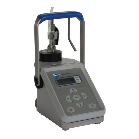
This section provides necessary information to install and connect the instrument. Should you have any questions, do not hesitate to contact your Hach representative regarding the installation procedure. The series 3650Ex Intrinsically Safe Portable Analyzer is a self-contained instrument configured to make oxygen or hydrogen gas concentration measurements with Electrochemical (EC) Sensors in a hazardous area, in either liquid or gaseous samples. -
Page 20: Sensor Installation
Installation 3.1 Sensor installation The electrochemical (EC) sensor connects to the instrument base through a 10-pin LEMO connector. A locking nut holds the sensor in place. Generally, the sensor is shipped already installed in the instrument. If this is not the case, for full installation instructions, please refer to the Sensor Manual provided with your instrument. -
Page 21: Sample Tube Adapter (Optional)
Installation 3.3 Sample tube adapter (optional) A model 32051A sample tube adapter can be attached to the flow chamber's inlet tubing. This adapter, in turn, attaches to 6 mm or ¼ inch stainless steel or flexible tubing using rubber gasket model 32813 (or, for 8 mm tubing, rubber gasket model 32814). - Page 22 Installation The interface box operates from 115 VAC or 230 VAC power. Make sure that the power is correct before connecting to a power supply. A green power LED is illuminated when the box is plugged into the power source. Two cables are supplied with the model 29122 interface box: •...
-
Page 23: Installation Completion Check List
Installation 3.6 Installation completion check list 3.6.1 Battery The instrument is designed to work on battery power. Install the Exproof lithium battery by first unscrewing the instrument's battery cap located on the right side of the instrument (refer to Figure 1 on page 17) with a coin or flat screwdriver. - Page 24 Installation...
-
Page 25: Section 4 Operating Information
Section 4 Operating Information 4.1 Operating controls The front panel of the instrument has a three-digit liquid crystal display (LCD). The LCD includes a right-side marker to distinguish between gas concentration and temperature display. This marker also indicates the measurement display units (ppm, ppb, %, etc.) depending on the instrument model. - Page 26 Operating Information To start the analyzer, press the keyboard POWER switch (located bottom left of the keyboard). When you turn power on, the instrument displays its model number briefly, and then starts in measurement mode. You can access other instrument functions by pushing one of these keys while turning power on: Sensor calibration.
-
Page 27: Taking Measurements
Operating Information 4.2 Taking measurements Once the system is calibrated, you should be able to begin taking measurements. Connect the top-mounted inlet to accept your sample, typically this is accomplished by connection to a sampling valve. The sample flow can be regulated by adjusting the knurled stainless steel knob on top of the flow chamber. -
Page 28: Storing Measurements In The Instrument
Operating Information 4.3 Storing measurements in the instrument The instrument will store up to 500 gas measurement values, labeled by numbers 0 through 499, along with the current date and time of each measurement. You have the choice of acquiring this information manually or automatically, as described below. Before storing measurements, you should verify the date and time settings of the instrument's internal clock, as described in Clock settings on page... -
Page 29: Manual Data Acquisition
Operating Information 4.3.2 Manual data acquisition Note: You cannot store measurement data manually if the instrument has already been set up to store the data automatically. 1. For the first measurement you wish to store, press the button once to display a sample number. -
Page 30: Viewing Stored Measurements
Operating Information 4.3.3 Viewing stored measurements 1. Switch the instrument (by pressing POWER key) 2. Hold down the Up Arrow button while switching the instrument back ON. The LCD displays a sample location number. 3. Scroll through the numbered sample locations of all the stored values using the Up Arrow Down Arrow... -
Page 31: Altering The Sampling Point Descriptions
Operating Information 4.4.2 Altering the sampling point descriptions For help in identifying the locations of various sampling points that are stored by the instrument, you may choose the Sampling Point Description command from the Logger menu to bring up the dialog box. The measurement values to be placed in positions 0 through 499 (identified as Text 0, Text 1... -
Page 32: Clearing Stored Values
Operating Information 4.4.6 Clearing stored values To clear all the values stored in the instrument via the WinLog97 program, choose the Clear Data command from the Logger menu. Since this action will clear the storage memory of the instrument, a warning appears first. Choose OK to bring up the next dialog box to confirm the clear action. - Page 33 Operating Information Click the TIMEBASE up/down pointers to change the time scale of the divisions of the chart. Each division mark along the baseline (1, 2, ...10) can be made to represent from 30 seconds to 2½ hours, providing from 5 minutes to 25 hours of continuously displayed samples. The chart updating rate is determined by the time scale selected.
- Page 34 Operating Information...
-
Page 35: Section 5 Options Setup
Section 5 Options Setup The WinLog97 program is an integral part of the analyzer. Running under Microsoft Windows®, it permits you to list and analyze up to 500 stored measurement values. The program also includes a special monitoring feature, which lets your computer act as a chart recorder, and enables a hardware test to ensure that the system is in good working order. -
Page 36: Instrument - Pc Connection
Options Setup The Configuration menu lets you see how your system has been configured for your application. You may change the PC's COM port, the sensor membrane, automatic data acquisition rate, or the sensor calibration mode. You may also lock out the instrument's button, or for calibration using a span gas, you may enter the span gas percentage. -
Page 37: Reviewing Instrument Configuration
However, should you see any unexpected items listed on your screen which you are unable to correct, please contact your Hach representative. 5.4 Configuring the instrument The 3650Ex analyzer can be readily configured for your application using the following commands in the Configuration menu. -
Page 38: Membrane Selection
Options Setup 5.4.2 Membrane selection You may find it necessary to use a different type of membrane for different applications. Naturally, with any membrane change, you will need to re-calibrate (refer to Sensor calibration on page 40). You should also consider the changes in required flow rates and response times, which are specified in the accompanying Sensor Manual. -
Page 39: Locking Out The Instrument's Cal Button
Options Setup 5.4.4 Locking out the instrument’s CAL button You can use the Configuration, Calibration Key Status menu to prevent an accidental sensor re-calibration from the instrument keyboard. Choose Disabled to lock out the keyboard button. To unlock this capability, choose Enabled. Choose OK when the desired mode is selected. -
Page 40: Dual Use (Model 3650Ex/113 Only)
Options Setup 5.4.7 Dual use (model 3650Ex/113 only) 5.4.7.1 Change from the PC Use the Configuration, Dual Use menu to change the measurement phase (either dissolved or gaseous) for the model 3650Ex/113 dual-use analyzer. Choose ppm (dissolved) to set the instrument for dissolved measurement in liquids, or % (gaseous) to set the instrument to gas phase measurement. -
Page 41: Section 6 Calibrations
Section 6 Calibrations 6.1 Atmospheric pressure equilibrium Since the instrument is sealed against moisture, you must open the barometric pressure sensor relief valve switch on top of the instrument (refer to Figure 1 on page 17 for actual location) to permit the instrument to achieve atmospheric pressure equilibrium, and take an accurate barometric pressure reading. -
Page 42: Sensor Calibration
Calibrations 6.4 Sensor calibration When delivered, the sensor is pre-calibrated. However, it should be re-calibrated on site, when being used for the first time, and always after a membrane change. If you have just replaced the membrane, allow at least half an hour for the membrane to settle before attempting to calibrate. If you want to verify the accuracy of the calibration, place the analyzer back in measurement mode and compare your displayed gas concentration against the value in the appropriate tables found in the accompanying Calibration Tables booklet. -
Page 43: Calibration In Line
Calibrations 6.4.2 Calibration in line The in line calibration procedure can be used to calibrate the sensor directly in line, against a liquid sample with a known dissolved gas concentration. To perform this type of calibration, the instrument must be set for calibration In line. Switch on the instrument, if necessary, and wait a minute or so for the displayed measurement to settle. -
Page 44: Calibration In Air (Oxygen Sensors Only)
Calibrations 6.4.3 Calibration in air (oxygen sensors only) The oxygen sensor can be accurately calibrated in air. To perform this type of calibration, the instrument must be set for calibration In air. In order to calibrate the sensor in air, you will need to extract it from its mounting or flow chamber, and wipe dry the sensor protection grille (if applicable). -
Page 45: Section 7 Maintenance And Troubleshooting
Section 7 Maintenance and Troubleshooting 7.1 Maintenance 7.1.1 Instrument If there are problems with the instrument, please contact your local Hach service representative. 7.1.2 Sensor For information on sensor maintenance and servicing, please refer to the accompanying Sensor Manual. 7.2 Troubleshooting If your analyzer is behaving strangely (failing to calibrate, giving inappropriate measurement values, etc.) and you have attempted to rectify the problem by servicing the sensor, but to no... -
Page 46: Display Test
Maintenance and Troubleshooting 7.2.3 Display test Choosing Troubleshooting, Display Test lets you perform a one-way communication between computer and instrument. Type a number in the Number box (you may also select one of three units positions for the LCD's rightmost indicator bar as well). Then choose Send. The number and indicator bar placement should appear on your instrument LCD. -
Page 47: Analog Voltages View
The Troubleshooting, Analog Voltage View gives a real-time look at voltages used by the system to transmit information about sensor current, temperature and pressure. This is useful when trying to identify an instrument problem with a Hach service representative either on-site or over the phone. - Page 48 Maintenance and Troubleshooting...
-
Page 49: Section 8 Part Lists
Section 8 Part Lists 8.1 Instrument configurations Part N° Description Substance measured: Oxygen, RS232 (serial) output: requires part no. 29122, 3650Ex/111 Special sensor: 31120E or GA2800 ATEX, Measurement units: ppm/ppb or ppm. Substance measured: Oxygen, RS232 (serial) output: requires part no. 29122, 3650Ex/112 Special sensor: 31120E or GA2800 ATEX, Measurement units: %/ppm or %. -
Page 50: Accessories
Part Lists 8.3 Accessories Part N° Description Adapter for attaching flow cell inlet tubing to customer's sample tube. Includes one 6 mm 32051A (32813) and one 8 mm (32814) rubber sealing gasket. - Page 51 Tel. +49 (0) 2 11 52 88-320 SWITZERLAND Fax (970) 669-2932 Fax +49 (0) 2 11 52 88-210 Tel. +41 22 594 6400 orders@hach.com info-de@hach.com Fax +41 22 594 6499 www.hach.com www.de.hach.com © Hach Company/Hach Lange GmbH, 2014, 2015, 2018–2019. All rights reserved.
Need help?
Do you have a question about the ORBISPHERE 3650 Atex and is the answer not in the manual?
Questions and answers