Hach ORBISPHERE 410 User Manual
Hide thumbs
Also See for ORBISPHERE 410:
- Basic user manual (438 pages) ,
- Quick operator's manual (13 pages) ,
- User manual (116 pages)
Table of Contents
Advertisement
Quick Links
Advertisement
Table of Contents

Related Manuals for Hach ORBISPHERE 410


Summary of Contents for Hach ORBISPHERE 410
- Page 1 DOC024.52.93001 ORBISPHERE Model 410 Analyzer USER MANUAL 11/2017, Edition 15...
-
Page 2: Table Of Contents
Table of Contents ......................5 Section 1 General Information 1.1 Disclaimer ............................ 5 1.2 Safety information ........................5 1.2.1 Use of hazard information ....................5 1.2.2 Safety precautions ......................5 1.2.3 Service and repairs ......................6 1.2.4 Precautionary labels......................6 1.2.5 Operating altitude........................ - Page 3 Table of Contents 4.2.6 Warning windows ......................36 4.3 Main menu structure........................37 ........................39 Section 5 View Menu 5.1 Selection of the view style ......................40 5.2 Configuration of the view styles....................41 ......................43 Section 6 Measurement Menu 6.1 Instrument configuration......................44 6.2 Measurement configuration......................44 6.3 Measured data storage ......................47 ......................49 Section 7 Calibration Menu...
- Page 4 Table of Contents 13.6 Boards info..........................88 13.7 Batteries ........................... 89 13.8 Software download ........................89 13.9 End application ........................89 ................91 Section 14 Maintenance and Troubleshooting 14.1 Instrument maintenance ......................91 14.2 Troubleshooting ........................91 14.3 List of events and alarms ......................92 14.4 Storage, handling and transportation..................
- Page 5 Table of Contents...
-
Page 6: Section 1 General Information
However, Hach Lange assumes no responsibility for any inaccuracies that may be contained in this manual. In no event will Hach Lange be liable for direct, indirect, special, incidental, or consequential damages resulting from any defect or omission in this manual, even if advised of the possibility of such damages. -
Page 7: Service And Repairs
1.2.3 Service and repairs None of the analyzer’s components can be serviced by the user. Only personnel from Hach Lange or its approved representative(s) is (are) authorized to attempt repairs to the system and only components formally approved by the manufacturer should be used. Any attempt at repairing the analyzer in contravention of these principles could cause damage to the analyzer and corporal injury to the person carrying out the repair. -
Page 8: Operating Altitude
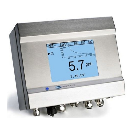
ORBISPHERE 410 analyzers are available as wall or pipe mount, and rack mount versions. The ORBISPHERE 410 uses a patented gas phase (or dissolved gas) ORBISPHERE sensor. -
Page 9: Product Recycling Information
General Information 1.3 Product recycling information ENGLISH Electrical equipment marked with this symbol may not be disposed of in European public disposal systems after 12 August 2005. In conformity with European local and national regulations (EU Directive 2002/96/EC), European electrical equipment users must now return old or end-of-life equipment to the manufacturer for disposal at no charge to the user. - Page 10 General Information SVENSKA Elektronikutrustning som är märkt med denna symbol kanske inte kan lämnas in på europeiska offentliga sopstationer efter 2005-08-12. Enligt europeiska lokala och nationella föreskrifter (EU-direktiv 2002/96/EC) måste användare av elektronikutrustning i Europa nu återlämna gammal eller utrangerad utrustning till tillverkaren för kassering utan kostnad för användaren. Obs! Om du ska återlämna utrustning för återvinning ska du kontakta tillverkaren av utrustningen eller återförsäljaren för att få...
-
Page 11: Product Disposal
European public disposal systems after 12 August 2005. Hach Lange will offer to take back (free of charge to the customer) any old, unserviceable or redundant analyzers and systems which carry the above symbol, and which were originally supplied by Hach Lange. -
Page 12: Restriction Of Hazardous Substances (Rohs)
General Information 1.5 Restriction of hazardous substances (RoHS) Dieses Informationsblatt enthält Angaben, die ausschließlich für den Export dieses Gerätes in die Volksrepublik China erforderlich sind. This document contains information which is only required for the export of this instrument into the People's Republic of China. - Page 13 General Information...
-
Page 14: Section 2 Specifications
Section 2 Specifications Specifications are subject to change without notice. 2.1 Technical specifications OPERATING CONDITIONS Operating temperature limits –5 to 50°C (23 to 122 °F) Storage temperature limits –20 to 70°C (–4 to 158 °F) Operating humidity limits 0 to 95% non condensing relative humidity Operating altitude From 0 to 2,000 m. -
Page 15: Hardware Description
Specifications One "instrument system alarm" relay per instrument 1A-30 VAC or 0.5A-50 VDC on a resistance load Normally closed [NC] (NO relay also available) when instrument is turned on. Opens when a system alarm is detected, and when it does not receive any signal. System alarm relay on the main board WARNING... -
Page 16: Security Level Table
Specifications Example: 410 / A / W1C0 0000 Analyzer model 410 • For oxygen measurement • Wall mounted • 100-240 VAC • 0/4 20 mA analog output • RS-485 • Standard software (English, French, German, Italian, Spanish, Russian, Japanese, Chinese) •... -
Page 17: Default Parameters
Specifications 2.5 Default parameters The table below indicates the factory default configurations. The instrument has these settings when started for the first time. Parameter Default settings Customer settings Disabled Security Measurement Measurement mode Continuous Data filter Disabled Sample phase Liquid Units ppm-ppb Display resolution... -
Page 18: Section 3 Installation
Section 3 Installation This section provides necessary information to install and connect the analyzer. The installation of the analyzer should be performed in accordance with relevant local regulations. DANGER Electrocution Hazard. Do not connect AC power to a 5 VDC powered model. WARNING Potential Electrocution Hazard. -
Page 19: Installation Check List
9. Adjust the settings for correction factors and interferences The instrument should now be ready for operation. If a problem occurs, refer to Troubleshooting on page 91. If the difficulty cannot be overcome, please contact your Hach Lange representative who will be happy to assist you. -
Page 20: Wall Mount And Pipe Mount Instruments
Installation 3.3 Wall mount and pipe mount instruments 3.3.1 Instrument dimensions Figure 1 Wall and pipe mount instrument dimensions (in millimeters) -
Page 21: Wall Mounting
Installation 3.3.2 Wall mounting Attach the U bracket provided to the wall with two screws (not provided). Tilt the instrument slightly backwards to align the bracket pins and the insertion slots, and slide the instrument onto the bracket as shown. Insert the 2 locking screws with washers through the side slots. -
Page 22: Connection Panel (Bottom Of Instrument)
Installation 3.3.4 Connection panel (bottom of instrument) Front panel door A square key is provided to open the instrument front panel locks. The two locks are located on the right side of the instrument on the top and bottom panels (number 8 in Figure 4 below). - Page 23 Installation Figure 5 Panel mount instrument dimensions (in millimeters)
-
Page 24: Mounting
Installation 3.4.2 Mounting WARNING Electrocution hazard. If the cable and connector for the power supply are not accessible after installation, an accessible local disconnection means for the instrument power is mandatory. 1. Cut an opening in the panel to accommodate the bracket frame provided (this is the same size as previous generations of ORBISPHERE type 3600 instruments). -
Page 25: Connection Panel (Bottom Of Instrument)
Installation Alternative instrument mounting procedure When it is not convenient to work from the back of the panel, the instrument can be connected before fitting in the panel. 1. Install the panel support frame in the panel opening 2. Slip the cables through the panel opening 3. -
Page 26: Connectors Assembly Instructions
Installation 3.5 Connectors assembly instructions WARNING Potential Electrocution Hazard. In order to maintain the NEMA/IP environmental ratings of the enclosure, use only conduit fittings and cable glands rated for at least NEMA 4X/IP65 to route cables into the instrument. 3.5.1 Cable gland wiring instructions A waterproof cable gland is provided each time a cable must be connected inside the instrument. -
Page 27: Connection To Mains Power Supply
Installation 3.6 Connection to mains power supply 3.6.1 Power supply connection (low voltage instruments) For low voltage instruments (10-30 VDC), connection to the mains power supply is with a 7-pin BINDER connector (supplied). Note: The connectors are grooved to avoid an incorrect fitting to the instrument. Connect the power cable to the connector as follows: Pin Connections: 1. -
Page 28: Power Supply Connection (High Voltage Instruments)
Installation 3.6.2 Power supply connection (high voltage instruments) High voltage instruments (100-240 VAC) have a 4-pin male connector pre-wired internally with a male BINDER connector ready for mains connection. A compatible female connector is supplied with the instrument. If this female connector was supplied with a mains power plug already pre-attached (cable part numbers 33031, 33032, 33033 and 33034) then the female connector can be plugged directly into the instrument power connector. -
Page 29: Connections To Electronic Boards
Installation Wire the female connector as follows: 1. Take the narrow end of the connector (4) in one hand and the main body (2) in the other and unscrew the two. Pull away the cable clamp (3) and unscrew the end plug (1) to reveal the four parts that make up the connector. -
Page 30: Electronic Boards Connectors
Installation 3.7.2 Electronic boards connectors Connectors P8 on the main board, and connectors J7 and J8 on the measurement board are made of two parts. Push down carefully the black levers on either side of the connector and pull it out securely. Perform all connections with these connectors unplugged. Once finished, attach the connectors to the boards by pushing them firmly in place (levers up). -
Page 31: Measurement Board
Installation 3.7.4 Measurement board The different measurement boards for the EC and TC sensors are illustrated in Figure 13 Figure 14 below. The type of board is easily identified by the color of the J8 connector. For EC boards this connector is colored orange, and for TC boards it is colored black. NOTICE It is extremely important that sensors are connected to the correct measurement board. -
Page 32: Measurement Alarm Relays
Temperature Brown Note: To change the type of sensor (e.g. from a 31xxx sensor to a 31xxxS smart sensor) contact your local Hach Lange representative. 3.8 Measurement alarm relays The three output relays are located on the measurement board (refer to... -
Page 33: Sensor Installation
Installation 3.9 Sensor installation 3.9.1 EC Sensors For EC sensor installation, servicing, and maintenance ensure you follow the instructions in the Sensor Installation and Maintenance manual that was supplied with the instrument. 3.9.2 TC Sensors For TC sensor installation, servicing and maintenance ensure you follow the instructions in the TC Sensor Installation and Maintenance manual that was supplied with the instrument. -
Page 34: Section 4 User Interface
Section 4 User Interface 4.1 Instrument The instrument front panel provides these user interfaces: A touch screen acting as display, touch pad and keyboard. Contrast can be adjusted. • A LED, showing when the instrument is on. • A buzzer which sounds each time the screen is touched, and when an event alarm is set. •... -
Page 35: Function Keys On The Header Bar
User Interface 4.2.1 Function keys on the header bar Shortcut to the user login window. Pressing this button for more than 2 seconds calls the ID and password window. Refer to Identification and authorization level on page Closed padlock indicates that the touch screen is locked. •... -
Page 36: Menu Navigation
User Interface 4.2.2 Menu navigation Pressing the “menu” button in the header bar calls the main menu. The display is made of three columns: The left column is the menus, or submenus (greyed out • options are not available) The center column shows a tree view of actual position •... -
Page 37: Identification And Authorization Level
User Interface 4.2.5 Identification and authorization level Once the access rights have been set, (refer to User management on page 80) it is necessary to log in as an authorized user to get access to the instrument functionalities and settings. Press the closed padlock for two seconds to open the identification window. -
Page 38: Main Menu Structure
User Interface 4.3 Main menu structure This is the structure of the main menu which is used to control every functionality of the instrument. These submenus are detailed in the following sections of this Operator Manual. Figure 24 Main menu structure... - Page 39 User Interface...
-
Page 40: Section 5 View Menu
Section 5 View Menu Figure 25 View menu... -
Page 41: Selection Of The View Style
View Menu 5.1 Selection of the view style Numeric view This is the default view. Display shows the numeric measurement value identified for the gas measurement channel, a graphic showing measurement value evolution during the set time frame, and sample temperature. This display can be configured to suit individual conditions and convenience. -
Page 42: Configuration Of The View Styles
View Menu Kurtosis Kurtosis is a parameter that describes the shape of a random variable’s probability distribution. The graphs on the left illustrate the notion of kurtosis. The lower curve has higher kurtosis than the upper curve. It is more peaked at the center, and it has fatter tails Figure 27 Kurtosis 5.2 Configuration of the view styles... - Page 43 View Menu...
-
Page 44: Section 6 Measurement Menu
Section 6 Measurement Menu Figure 28 Measurement menu... -
Page 45: Instrument Configuration
Measurement Menu 6.1 Instrument configuration Continuous mode description Continuous mode is typically used for process measurement. Continuous mode cycle Every 2 sec. measurements are refreshed on the display • The relays and the analog outputs are updated • Measurements are continuously stored in memory (volatile and non volatile memory) according to •... - Page 46 Measurement Menu Measurement alarms configuration Set the thresholds for the low/high concentration levels, according to the application. Each alarm type can be individually enabled or disabled without losing its settings. These events can activate the relays and can be displayed. Low-low: 2nd stage for too low concentration •...
- Page 47 Liquid to gas factor: Enable correction as appropriate. If checked, the percentage correction factor • must be entered. This value cannot be negative. Note: If you believe you need to enable these corrections, it is advisable to contact a Hach Lange Service Representative first. Oxygen interference configuration These options are available to take into account the influence of some components or gases in the sample during measurement.
-
Page 48: Measured Data Storage
Measurement Menu 6.3 Measured data storage Measured data storage There is one measurement file which contains the data generated by the measurement cycle. The measurement files are updated in volatile memory, and regularly copied in non-volatile memory (file back-up). At start up, the measurement files in volatile memory are updated with the files from the non-volatile memory. - Page 49 Measurement Menu...
-
Page 50: Section 7 Calibration Menu
Section 7 Calibration Menu Figure 30 Calibration menu Note: The amplifiers calibration option is reserved for Hach Lange service technicians only, and is therefore not explained in this manual. - Page 51 Calibration Menu Figure 31 Calibration menu (cont. from previous page)
-
Page 52: Definitions
Calibration Menu 7.1 Definitions Definitions To calibrate the gas to measure (main gas), the user usually puts the sensor in the main gas without any interfering gas. Calibrations can only be performed once the instrument has been installed, configured and the channel has been set up. -
Page 53: O 2 Sensor Calibration
Calibration Menu A calibration screen will be displayed showing current measurement data Calibration results which is continually refreshed. The value “% ideal current” is a percentage of the current against the ideal current for the membrane type selected. If this percentage is not within the accepted range, an error message is displayed and the calibration process fails (refer to Calibration errors (EC and TC sensors) on page... -
Page 54: Tc Gas Sensor Calibration
Calibration Menu 7.3 TC gas sensor calibration Calibration of the measured gas Before initiating a calibration process, the calibration parameters must be Start set by pressing on the Modify button. The last calibration parameters are memorized, so this step can be ignored if the correct parameters are already set. -
Page 55: Calibration Errors (Ec And Tc Sensors)
Calibration Menu 7.4 Calibration errors (EC and TC sensors) Calibration errors (EC and TC sensors) The calibration is not possible in the following circumstances: When the "ratio ideal current" is greater than 170% or smaller than 30% • When the sensor cannot measure (thermal cut off, sensor out, etc.) •... -
Page 56: Section 8 Inputs/Outputs Menu
Section 8 Inputs/Outputs Menu Figure 32 Inputs/Outputs menu... -
Page 57: Configure Snooze
Inputs/Outputs Menu 8.1 Configure snooze Configure snooze In the event of an alarm, the “snooze” button stops the instrument buzzer and returns all the relays in the instrument to their normal state during a "snooze time". Enter the snooze time in seconds and press OK. 8.2 View inputs/outputs View inputs/outputs This view option displays the state of the 3 alarm relays (on or off), and the analog output current (or... -
Page 58: Analog Outputs
Inputs/Outputs Menu 8.4 Analog outputs Figure 33 Analog outputs menu... - Page 59 Inputs/Outputs Menu Analog outputs There are three analog outputs available. These outputs are configurable in terms of function, content, and behavior through the instrument menus. Analog outputs are used to output a voltage or a current which is a function (e.g. a linear characteristic) of a measurement: AOut = f (M). The analog outputs can be typically connected to a PLC.
- Page 60 Inputs/Outputs Menu Analog outputs (continued) Set the type of measurement that will be transmitted through each output Channel configuration channel, and the output characteristics. Meas. type: Select between the type of measurements available in the • rolling list. Characteristics: Select either Linear, Tri-linear or None. Refer to •...
- Page 61 Inputs/Outputs Menu Analog outputs (continued) The calibration of the analog output is aimed at aligning the internally Calibration of the analog calculated current to the real current output. This was performed at factory, output but could become necessary again because of electronic tolerances. A precision amperometer (or voltmeter for the voltage versions) connected at the corresponding analog output connection point is required.
-
Page 62: Analog Output Characteristics
Inputs/Outputs Menu 8.5 Analog output characteristics Analog output characteristics The "Linear" output is the default setting for the analog output. It is “Linear” analog output illustrated below (4-20 mA output is shown, 0-20 mA or 0-5 V settings are similar). The goal of this setting is to use all the points available on the slope from 4 mA to 20 mA to show the range of measurements that are usual in the measured process. - Page 63 Inputs/Outputs Menu Analog output characteristics (continued) The "Tri-linear" output brings benefits over the “Linear output” discussed “Tri-linear” analog before. It is illustrated below (4-20 mA output is shown, 0-20 mA or 0-5 V output settings are similar). Compared to the “Linear” mode, the expected range of measure is Range 2. A Range 1 and 3 are available to show the measures falling out of this Range 2, but normally at a lower resolution.
- Page 64 Inputs/Outputs Menu Tri-linear Range Measurement M Resolution R 1: AOL > I > 4 M=MLL+(ML-MLL) (I-4)/(AOL-4) R=(ML-MLL) 20/((AOL-4) 1010) 4-20 mA 2: AOH > I > AOL M=ML+(MH-ML) (I-AOL)/ (AOH-AOL) R=(MH-ML) 20/((AOH-AOL) 1010) 3: 20 > I > AOH M=MH+(MHH-MH) (I-AOH) / (20-AOH) R=(MHH-MH) 20/((20-AOH) 1010)
- Page 65 Inputs/Outputs Menu...
-
Page 66: Section 9 Communication Menu
Section 9 Communication Menu Figure 34 Communication menu The external RS-485 port of the main board is directly connected to a RS-485 bus (single twisted pair). Optionally it can be connected to a fieldbus module (gateway). The RS 485 menu allows to select between RS485 simple or Profibus DP communication protocol, depending on application. -
Page 67: Rs-485 Simple Mode Configuration
Communication Menu 9.1 RS-485 simple mode configuration This protocol allows the instrument to output data to an external device (PLC, SCADA, PC, etc.). The communication is unidirectional. The data are output on the RS-485 link as simple ASCII text. If for instance you use a PC, the data can be easily visualized and saved in a file using the "Hyperterminal"... -
Page 68: Data Available
Communication Menu 9.1.1 Data available All individual data are separated by at least one tabulation character (ASCII code=0x09). For the cyclic measurements, the data format is detailed. For the files, only one example for each file is given to explain the data format. Cyclic measurements 1. - Page 69 Communication Menu Gas sensor calibration report example Calibration report nb 1 Type .....Sensor calibrated on this instrument Date (yy.mm.dd - hh:mm) ..05.02.17 - 18:40 Operator .
-
Page 70: Example Of Use
Communication Menu Configuration report example The "Configuration" below is given for a one channel instrument. INSTRUMENT CONFIGURATION Measurement mode ..Continuous mode Pressure unit ....[bar] Temperature unit . -
Page 71: Profibus-Dp Communication (Optional)
Communication Menu 9.2 PROFIBUS-DP communication (optional) 9.2.1 Installation On the ORBISPHERE CD, there is an “Orbi3218.gsd” and an “Orbi3218.bmp” file available in the “Profibus DP” folder to help configure the PROFIBUS-DP. The GSD file contains the following elements: The module Gateway Version >= 2.0 - 1 channel for receiving data from the instrument. •... -
Page 72: Input/Output Data
Communication Menu 9.2.2 Input/Output data The main board: Writes the latest measurement data to the Profibus Input Buffer. • Checks if a command written by the Profibus Master must be executed (Profibus Output • Buffer). If a command is to be executed, the instrument executes it and writes the result (status, data, etc.) in the Profibus Input Buffer. - Page 73 Communication Menu The gas, temperature and barometric pressure unit values are coded as defined in the following tables: Barometric Gas unit Value Temperature unit Value Value pressure unit mbar °C mbar °F psia atm. psia atm. mbar->bar Pa->KPa %Vbar ppm Vbar %Vext ppm Vext ppm Vbar->%Vbar...
- Page 74 Communication Menu Commands The “Command Output Buffer” is formatted as follows: Name Type Size Offset Output command toggle (OCT) Output byte 8 bits Output command ID (OCI) Output byte 8 bits Output command data byte 1 (OCD1) Output byte 8 bits Output command data byte 2 (OCD2) Output byte 8 bits...
- Page 75 Communication Menu Activate sensor command - output Name Value Comment Command ID Channel number: OCD1 0 = Channel 1 Sensor activation: OCD2 0 = Deactivate the EC sensor 1 = Activate the EC sensor OCD3 Not used OCD4 Not used Activate sensor command - input Name Value...
-
Page 76: Usb-A Port (Host)
Communication Menu 9.3 USB-A port (host) This option allows the export or import of data from an external mass storage device. The device must first be connected to the instrument through the USB-A port. Select one of the two import options (product list or access table) to import data from the storage device. - Page 77 Communication Menu Once a valid username/password combination has been entered, the initial web page will be displayed giving a list of options: Click on any of these options and the data will be displayed on the PC screen. The following shows an example of the screen when selecting the Current Measurement option:...
-
Page 78: Printer
Communication Menu 9.5 Printer This menu provides the facility to print a number of reports directly to a printer. The printer must be connected to the instrument through the instrument USB-A port. The following information is available for printing: Calibration reports •... -
Page 79: Printer Error Messages
Communication Menu 9.5.2 Printer error messages Error message Meaning Indicates that no printer has been detected. Check that the printer is Printer not available connected to the USB-A port and is powered on. Indicates that the printer is out of paper. In cyclic mode, it is necessary to activate cyclic printing after reloading paper in the printer. -
Page 80: Section 10 Security Menu
Section 10 Security Menu Figure 35 Security menu Note: When the instrument is started for the very first time, security is disabled by default. It is highly recommended that each user be entered into the system and given appropriate access rights as soon as possible to avoid any unauthorized access. -
Page 81: Configure Security
Security Menu 10.2 Configure security Configure security This enables defining the users with their access level when the software starts for the first time. It is possible to configure several parameters related to confidentiality. This requires a user access level 4. Note: Access rights are disabled by default. -
Page 82: Section 11 Products Menu
Section 11 Products Menu Figure 36 Products menu... - Page 83 Products Menu Products This option allows users to save and/or use previously saved product configurations. A maximum of 100 different product configurations can be stored in the instrument. The basic measurement configuration (gas to analyze, gas unit, alarm limits, analog outputs, etc.) can be set up for a product and will be automatically used by the instrument when that product is selected.
-
Page 84: Section 12 Global Configuration Menu
Section 12 Global Configuration Menu Figure 37 Global configuration menu Global configuration The global configuration option allows users to save, and use previously saved, instrument configurations. A maximum of 10 configurations can be saved, with configuration 0 (zero) the instrument default. - Page 85 Global Configuration Menu...
-
Page 86: Section 13 Services Menu
Section 13 Services Menu Figure 38 Services menu - Part 1... - Page 87 Services Menu Figure 39 Services menu - Part 2...
-
Page 88: Sensor Diagnostics
For more information on this, please refer to the manual delivered with the sensor. This is a diagnostic tool for Hach Lange technicians. This feature will allow Null current checking the ability of the EC measurement board to measure a null current. -
Page 89: Language Selection
Continuous purge button. If the measured and recommended values differ by a large margin, please contact your Hach Lange representative for advice. 13.2 Language selection Language selection Check the language as required and restart the instrument to apply the change. The instrument will restart in the language selected. -
Page 90: Batteries
13.8 Software download Software download For Hach Lange technician use only. Used when reloading the software for new versions. This ends the application. User must stop and restart the instrument to restart the program. 13.9 End application End application... - Page 91 Services Menu...
-
Page 92: Section 14 Maintenance And Troubleshooting
14.1 Instrument maintenance CAUTION Personal Injury Hazard. Any instrument maintenance should be carried out by a qualified Hach Lange Service Technician. Please contact your local representative should you feel any maintenance or instrument adjustments are required 14.2 Troubleshooting The possible events, along with the text message displayed on the instrument numeric view... -
Page 93: List Of Events And Alarms
Maintenance and Troubleshooting 14.3 List of events and alarms Table 4 List of Events Bit mask Event Name Description value (32 type bits long) Measure Normal measurement mode. 0x00000000 Filter enabled The gas measurements are filtered. 0x00000001 Sample measurement The sample measurement is started. 0x00000002 Meas. -
Page 94: Section 15 Part Lists
Description 29089 Purge gas pressure regulator kit for TC sensors 10 wire cable to connect 31xxx sensors to Orbisphere 410/510 wall and panel 32501.03 instrument, length 3m LEMO 10 adapter to connect 32505 type sensor cable to 410 or 510 wall and 32517.00... - Page 95 Part Lists...
-
Page 96: Section 16 Glossary
Section 16 Glossary 16.1 Gas units Unit Meaning percentage, by weight. A concentration of 100% air corresponds to liquid saturated with air at current % air pressure and temperature. The equivalent concentration of O is approximately 20% O in normal conditions. - Page 97 Glossary A device operating as a master will poll one or more devices operating as a slave. This means a Master / Slave modes slave device cannot volunteer information; it must wait to be asked for it. Parallel communication represents a connection in a computer system in which the bits of a byte Parallel communication are transmitted over separate channels at the same time.
- Page 98 Tel. +49 (0) 2 11 52 88-320 SWITZERLAND Fax (970) 669-2932 Fax +49 (0) 2 11 52 88-210 Tel. +41 22 594 6400 orders@hach.com info-de@hach.com Fax +41 22 594 6499 www.hach.com www.de.hach.com © Hach Company/Hach Lange GmbH, 2006–2017. All rights reserved.
Need help?
Do you have a question about the ORBISPHERE 410 and is the answer not in the manual?
Questions and answers