
Related Manuals for Hach Sigma 950


Summary of Contents for Hach Sigma 950
- Page 1 Catalog Number 3314 Sigma 950 Flow Meter INSTRUMENT MANUAL © Hach Company, 2002–2004, 2008. All rights reserved. Printed in the U.S.A. sp/dk 11/08 5ed...
-
Page 3: Table Of Contents
Section 1 Safety Precautions ......................5 1.1 Use of Hazard Information ......................5 1.1.1 Precautionary Labels ......................5 1.2 Hazardous Locations ........................6 1.3 Confined Space Entry ........................6 1.4 FCC Requirements ........................7 1.5 Service Requirements........................8 Section 2 Specifications ........................ - Page 4 6.5.1 Submerged Depth Only Sensor Connection ..............42 6.5.2 Submerged Depth Only Sensor Programming ..............42 6.5.3 Submerged Depth Only Sensor Calibration ..............42 6.6 Bubbler ............................44 6.6.1 Bubbler Connections ......................44 6.6.1.1 Meter-End Cable Terminations.................45 6.6.1.2 Routing the Bubbler Line ..................45 6.6.2 Bubbler Installation ......................46 6.6.2.1 Installation Guidelines ....................46 6.6.3 Depth Only and Bubbler Area/Velocity Calibration............46 Section 7 Optional Device Installation...
- Page 5 8.4 Alarm Relays..........................68 8.4.1 Alarm Relay Connections ....................68 8.4.2 Alarm Relays Programming ....................69 8.4.2.1 Trouble Alarms......................69 8.4.2.2 Set Point Alarms ...................... 70 Section 9 Maintenance ........................71 9.1 Routine Maintenance ......................... 71 9.1.1 Calibration......................... 71 9.1.2 Cleaning the Case ......................71 9.1.3 Maintaining Desiccant Cartridges and Desiccant .............
-
Page 7: Section 1 Safety Precautions
Section 1 Safety Precautions Please read this entire manual before unpacking, setting up, or operating this instrument. Pay particular attention to all danger and caution statements. Failure to do so could result in serious injury to the operator or damage to the equipment. Do not use or install this equipment in any manner other than that which is specified in this manual. -
Page 8: Hazardous Locations
Safety Precautions 1.2 Hazardous Locations The Sigma 950 Flow Meter is not approved for use in hazardous locations as defined in the National Electrical Code. DANGER Although some Hach products are designed and certified for installation in hazardous locations as defined by the National Electrical Code, many Hach products are not suitable for use in hazardous locations. -
Page 9: Fcc Requirements
Safety Precautions • Toxic materials which upon contact or inhalation, could result in injury, impairment of health, or death. Confined spaces are not designed for human occupancy. They have restricted entry and contain known or potential hazards. Examples of confined spaces include manholes, stacks, pipes, vats, switch vaults, and other similar locations. -
Page 10: Service Requirements
It is the responsibility of users requiring service to report the need for service to the manufacturer, or to one of our authorized agents. Service can be facilitated throughout our office: Hach Company 5600 Lindbergh Drive, P.O. Box 389 Loveland, CO 80539... -
Page 11: Section 2 Specifications
Section 2 Specifications Specifications are subject to change without notice. General Dimensions 34.3 cm H ´ 25.4 cm W ´ 24.1 cm D (13.5 in. ´ 10.0 in. ´ 9.5 in.) Weight 5 kg (11 lb) not including power source NEMA 4X, 6 with front cover open or closed Enclosure UV resistant, stable from -40 to 80 °C (-40 to 176 °F) -
Page 12: Specifications
17 mm ´ 12.7 cm (0.67 in. ´ 5 in.) with 19.5 mm (0.75 in.) mpt cable end Rain Gauge Input For use with Hach Tipping Bucket Rain Gauge. General Information Flow meter records rainfall data in 0.01 in. increments. - Page 13 Specifications Communications RS232 - up to 19,200 baud General Information Modem - 14400 bps., V.32 bis, V.42, MNP2-4 error correction. V.42 bis MNP5 data compression. MNP 10-EC Cellular Protocol Pager Sensor Specifications ® SCADA-Modbus communication protocol (standard) via RS232 or optional modem Bubbler Sensor Accuracy ±0.003 m (0.011 ft) linearity and hysteresis at 22 °C (72 °F), from 0.01 to 11.75 ft...
- Page 14 Specifications Ambient Operating -18 to 60 °C (0 to 140 °F) Temperature Material PVC housing with Buna-N acoustic window Cable 4-conductor with integral stainless steel support cable Cable Length 7.6 m (25 ft.) standard (custom lengths are available) Crystal Specification 50 kHz, 11.5°...
- Page 15 Specifications Cable Length 7.6 m (25 ft) standard, custom lengths up to 30 m (100 feet) Crystal Specification 75 kHz, 7° included beam angle Dimensions 4.44 cm (1.75 in.) maximum diameter, 31.435 cm (12.375 in.) long (transducer only) Dedicated Mounting Rings, Permanent Mounting Bracket (installs directly to pipe wall), Mounting Adjustable Mounting Band Kit.
- Page 16 Specifications Depth Accuracy: ±2% of reading Standard Sensor Range: 0.005 m–3.5 m ±0.007 m (0.018–11.5 ft ±0.023 ft) Extended Range: 0.005 m–10.5 m ±0.021 m (0.018–34.6 ft ±0.07 ft) Maximum Allowable Depth: 3x over pressure Operating Temperature Range: 32 to 160 °F (0 to 71 °C) Compensated Temperature Range: 32 to 86 °F (0 to 30 °C) Depth Temperature Error:...
-
Page 17: Section 3 Introduction
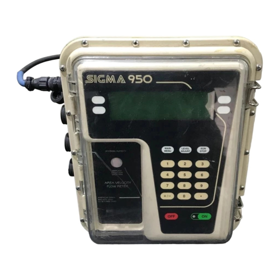
ASCII protocol. This software protocol communicates with the instrument via an RS232 connection. Using Hach’s integrated sewer system management software, users can download, remotely program, and conduct other data manipulation via RS232 connection or the optional modem. 3.2 Front Panel Features and Controls The 950 Flow Meter case has several unique features, all designed to simplify installation, operation, and maintenance. - Page 18 Introduction Figure 1 950 Flow Meter Front Panel Item # Description Function The menu bar appears in a black band on the top edge of the display. The upper left corner of the Menu bar menu bar shows the time and date. The upper right corner shows the name of the current menu. The 950 Flow Meter liquid crystal display (LCD) works in conjunction with the four soft keys as a guide Display through all programming steps.
-
Page 19: Power Indicator Light
Introduction An optional six-digit non-resettable mechanical totalizer is available for the flow meter. Located below the Humidity Indicator, the totalizer indicates total flow and supplements the internal software totalizers (one resettable and one non-resettable) that are configured during programming. Mechanical The totalizer can be configured for all conditions and installations because flow units and scaling are Totalizer selectable. - Page 20 Introduction...
-
Page 21: Section 4 Controller Installation
Section 4 Controller Installation DANGER Some of the following manual sections contain information in the form of warnings, cautions and notes that require special attention. Read and follow these instructions carefully to avoid personal injury and damage to the instrument. Only personnel qualified to do so, should conduct the installation/maintenance tasks described in this portion of the manual. -
Page 22: Unpacking The Instrument
Controller Installation 4.1 Unpacking the Instrument Remove the 950 Flow Meter from its shipping carton and inspect it for any visible damage. Contact Hach Customer Service at 1-800-227-4224 if any items are missing or damaged. 4.2 Choosing the Proper Site The accuracy of your flow measurements greatly depends on the suitability of your monitoring site. -
Page 23: Suspension Harness Installation (Optional)
Controller Installation Figure 2 Wall Mounting Bracket 4.3.2 Suspension Harness Installation (Optional) Use the optional Suspension Harness (P/N 2889) to suspend the flow meter in a manhole or similar site. The suspension harness has two captive ¼-20 S.S. mounting screws attached to the top of two threaded inserts on the back of the flow meter. -
Page 24: Installing The Power Supply
Controller Installation Figure 3 Manhole Rung Hanger Place over ladder rung. Connect bottom inserts to meter. 4.4 Installing the Power Supply The 950 Flow Meter is designed to accept either the manufacturer’s 12 V dc battery pack or ac power converter. 1. -
Page 25: Interface Connector Descriptions
Controller Installation 4.5 Interface Connector Descriptions Note: All interface receptacles are covered with push-on caps. These caps are designed to protect the connector pins from dirt and moisture and should be attached to any receptacle not in use. The interface connector ports are located on the left side of the flow meter case. The 950 Flow Meter comes standard with three interface ports. -
Page 26: Sampler
Controller Installation 4.7 Sampler 4.7.1 Sampler Connections The sampler interface receptacle is used to connect a wastewater sampler to the 950 Flow Meter. Table 3 Sampler Connector Pin Assignments Pin Signal Description Wire Color Purpose Rating 12 V dc (input only) orange Pin A may receive power from an external device, 500 mA 12 V dc (w/battery) -
Page 27: Section 5 Basic Programming Setup
Section 5 Basic Programming Setup 5.1 Initial Power-Up of Meter After power is applied, the flow meter performs a complete diagnostic self-test and displays the menu shown when the unit was last turned off. The Main Menu is the starting point for all programming operations. - Page 28 Basic Programming Setup 11:00 AM 21 - APR - 01 * Main Menu* MODIFY LOGIN ALL ITEMS MODIFY REVIEW ALL SELECTED ITEMS ITEMS READY TO START 2-B. Press to cycle through the flow unit choices. Refer to Table 4 CHANGE CHOICE flow unit choices.
- Page 29 Basic Programming Setup 3-C. Press to cycle through each of the level unit choices. Press CHANGE CHOICE to continue to primary device setup. ACCEPT Step 4 - Primary Device Note: Selecting the appropriate primary device is critical for proper flow rate calculations. 4-A.
- Page 30 Basic Programming Setup Table 7 Weir Choices (continued) Weir Description Non-Contracted Rectangular Crest Width is in. or cm (1–960 in. or 2.54–2438 cm) Thel-Mar Size in inches. (6, 8, 10, 12 or 15 in.) V-Notch Angle of notch in degrees (22.5 to 120°) Angle of notch in degrees (22.5–120°), notch depth in inches, rectangular width in inches Compound V-Notch (0–120 in.
- Page 31 Step 7 - Site ID Note: A text Site ID may be programmed via Hach's management software and an RS232 connection. Creates an 1–8 digit site identification number. The site ID will appear on all data printouts. This feature is useful when multiple sites are monitored using a single flow meter or if data readings from multiple flow meters are collected.
- Page 32 Basic Programming Setup 9-E. Read the Velocity cutoff warning on the screen. Press any key to continue. 9-F. Enter the Velocity Cutoff, using the numeric keypad. Press ACCEPT to continue. 9-G. Enter the Velocity Default using the numeric keypad. Press to end the ACCEPT basic programming setup.
- Page 33 Basic Programming Setup Status Description Program is Running Data Logging, 4-20 mA outputs, sampler control and alarm checking are active. Program is Halted Logging stops until the program is restarted. It continues with the last logged value when restarted. 4–20 mA outputs remain unchanged Sampler control is disabled Alarm checking is disabled Program is Complete or Ready to Start...
- Page 34 Basic Programming Setup...
-
Page 35: Section 6 Sensor Installation
Section 6 Sensor Installation An individual Sigma 950 flow meter may have one or more of the following sensors: • Downlook Ultrasonic Sensor • Submerged Pressure Area/Velocity • Submerged Pressure Sensor Sensor • In-Pipe Ultrasonic Sensor • Velocity-Only (Wafer) Sensor •... -
Page 36: Downlooking Ultrasonic Depth Sensor Calibration
Sensor Installation Figure 5 Remote Ultrasonic Sensor Option Clear Shield Enclosure 13.97 x 22.86 x 4.0 cm (5.5 x 9.0 x 4.0 in.) To flow meter Cable (P/N 2716) Customer-supplied conduit to 950 flow meter. Cable (P/N SE 818) Ultrasonic Transducer 6.1.3 Downlooking Ultrasonic Depth Sensor Calibration Calibrate the current water level via one of two methods;... -
Page 37: Sensor Height
Sensor Installation 3. Select Standard as the type of Ultrasonic Transducer using the soft CHANGE CHOICE key. Press to continue. ACCEPT Temperature Time Constant The speed of sound in air varies with the temperature of the air. The ultrasonic sensor is equipped with temperature compensation to help eliminate the effect of temperature variation under normal site conditions. -
Page 38: In-Pipe Zero Deadband Ultrasonic Depth Sensor
Sensor Installation 6.2 In-Pipe Zero Deadband Ultrasonic Depth Sensor The in-pipe zero deadband ultrasonic depth sensor is used in pipes where level measurement near the top of the pipe is desired. The sensor will read the level until liquid reaches from the bottom of the sensor housing. 6.2.1 In-Pipe Zero Deadband Ultrasonic Depth Sensor Connection Table 12 In-Pipe Zero Deadband Ultrasonic Depth Sensor Connector Pin Assignments... - Page 39 Sensor Installation 7. Enter the ambient air temperature at the transducer location. For optimum results, allow enough time (100 minutes) to ensure that the sensor is at equilibrium with the surrounding ambient temperature. The speed of sound in air varies with the temperature of the air. The ultrasonic sensor is equipped with temperature compensation to help eliminate the effect of temperature variation under normal site conditions.
-
Page 40: Submerged Area/Velocity Sensor
Sensor Installation Figure 6 Side View of In-Pipe Minimum distance to reflecting obstruction (2 m (82 in.)) Ultrasonic Sensor Distance from Sensor (Range: 0 to 4.08 m (13.4 ft)) Internal Deadband (18 cm (7.09 in.)) 45° Deflector 1. From the Main Menu, select OPTIONS>ADVANCED OPTIONS>... - Page 41 Sensor Installation 3. Connect the tubing in the cable to the clear tubing in the box that is already connected to the exit fitting. 4. Slip the cable in or out of the box sufficiently to create a slight loop in the wires and tubing to allow strain relief and then tighten the cable-clamp hex nut.
-
Page 42: Submerged Area/Velocity Sensor Programming
Sensor Installation Table 13 Submerged Area/Velocity Sensor Connection Pin Assignments Signal Description Wire Color depth (-) black depth (+) white 6.3.3 Submerged Area/Velocity Sensor Programming 1. If the flow meter is equipped with multiple sensors, from the Main Menu, select OPTIONS>LEVEL SENSOR. -
Page 43: Low Profile Velocity-Only (Wafer) Sensor Connection
Sensor Installation sensor. The streamlined shape of the velocity-only sensor allows velocity measurement in very low-flow conditions. When used in conjunction with a level sensor, the meter can calculate flow. 6.4.1 Low Profile Velocity-Only (Wafer) Sensor Connection Note: Use bare-lead sensor and junction box for conduit installation. The low profile velocity-only sensor connector is located on the right side of the flow meter (when facing the flow meter) and is labeled Velocity. -
Page 44: Submerged Depth Only Sensor Connection
Sensor Installation sensor increases. The voltage is read by the microprocessor in the 950 Flow Meter at a regular interval and converted to a number which represents the level in the flow stream. The level reading can then be converted by the meter to a flow rate based on the mathematical formula for the selected primary device. - Page 45 Sensor Installation 3. Lift the sensor out of the water and hold it in the air in the same orientation that you selected in the previous step (horizontal or vertical) (Figure 8). Press ACCEPT continue. Figure 8 Lifting the Sensor Out of the Water Horizontal Vertical 4.
-
Page 46: Bubbler
Sensor Installation b. Measure the depth from the bottom of the bucket to the surface of the water (D1) (Figure 10) and enter the value using the numeric keypad. Press ACCEPT continue. Figure 10 Measuring Submerged Depth, Horizontal Orientation 6.6 Bubbler The 950 Bubbler Flow Meter utilizes the bubbler method of level measurement. -
Page 47: Meter-End Cable Terminations
Sensor Installation • Reference Port—This port provides a reference to atmosphere. The flow meter measures level by comparing the back pressure against the bubble in the bubbler line with ambient air pressure. As the water level increases, the back pressure pushing against the bubble increases. -
Page 48: Bubbler Installation
Sensor Installation 6.6.2 Bubbler Installation 6.6.2.1 Installation Guidelines • Locate the end of the bubbler line at the proper head measurement point for that primary device. All weirs and flumes either come equipped or can be retrofitted with a connection for the bubbler line. Stainless steel bubbler line extensions are available where no provisions have been made. - Page 49 Sensor Installation power, keep bubble rates at one bubble per second. Set the Auto-Purge intervals to at least 30 minutes. To set the bubble rate, highlight the selection using the SET BUBBLE RATE DOWN arrow soft keys, then press the soft key.
- Page 50 Sensor Installation...
-
Page 51: Section 7 Optional Device Installation
Section 7 Optional Device Installation This section describes how to set up a rain gauge to the 950 Flow Meter as well as how to install the optional water quality probes (pH, ORP, Dissolved Oxygen, Conductivity, Temperature Probe). 7.1 Rain Gauge 7.1.1 Rain Gauge Connection An external “tipping bucket”... -
Page 52: Ph Probe
Optional Device Installation 7.2 pH Probe 7.2.1 pH Probe Connection Table 17 pH Connector Pin Assignments Signal Description +5 V dc ground reference pH/ORP 5 V dc -RTD The pH probe consists of five wires, three for the pH probe and two for the temperature probe. -
Page 53: Orp Probe
Optional Device Installation 3. Enter the temperature of the first buffer solution using the numeric keypad. Press to continue. ACCEPT 4. Press the to select the pH for the first buffer solution (4, 7, or 10 CHANGE CHOICE pH), then press to continue. -
Page 54: Orp Preamplifier/Junction Box Calibration
Optional Device Installation 6. Select another channel to configure or press to back up one step. Press the RETURN function key to return to the Main Menu. MAIN MENU 7.3.3 ORP Preamplifier/Junction Box Calibration Calibration of the ORP input circuit requires a source of dc voltage between 500 and 2000 m V dc. -
Page 55: Dissolved Oxygen Probe Temperature Programming
Optional Device Installation 7. Select another channel to configure or press to back up one step. Press the RETURN function key to return to the Main Menu. MAIN MENU 7.4.3 Dissolved Oxygen Probe Temperature Programming 1. From the Main Menu, select OPTIONS>ADVANCED OPTIONS>DATALOG 2. -
Page 56: Conductivity Probe
Optional Device Installation 7.5 Conductivity Probe 7.5.1 Conductivity Probe Connection The pre-amp (P/N 3369 or 3212) is required. Plug the probe into the pre-amp and plug the pre-amp into the 950 Flow Meter. Table 20 Conductivity Pin Assignments Signal Description Wire Color +12 V dc white... -
Page 57: Conductivity Probe Calibration
Optional Device Installation 6. Press to select temperature units (°C, °F). CHANGE CHOICE Press ACCEPT 7.5.4 Conductivity Probe Calibration 1. From the Main Menu, select OPTIONS > ADVANCED OPTIONS > CALIBRATION > CONDUCTIVITY. 2. Clean and dry the probe. 3. Place the sensor and thermometer in the calibration solution. The temperature sensor is located in the middle of the sensor body allowing the probe to be completely submerged in the solution. - Page 58 Optional Device Installation 7. Using the value that was calculated in step 6, enter the conductivity of the solution then press . Conductivity calibration is complete. ACCEPT Calibrating the Conductivity Temperature This calibration is necessary only when logging temperature. 1. Place the probe in a liquid. 2.
-
Page 59: Section 8 Communications Setup
Section 8 Communications Setup Data in the 950 Flow Meter can be transferred to a personal computer (PC) data management software by using a direct cable between the PC and meter, the cellular modem option, standard modem, or the portable Data Transfer Unit (DTU). See Figure The Data Transfer Unit (DTU) is a hand-held portable device that allows the user to connect to the flow meter using an RS232 serial cable. -
Page 60: Rs232 Programming
Communications Setup Table 22 RS232 Connector Pin Assignments Signal Description Wire Color yellow black green Cable Required RS232 Flow Meter to PC Cable Assembly, 10 ft (3.0 m) long, 6-pin connector on one end, 9-pin D-type connector on the other end (P/N 1727) (9-pin to 25-pin D-type adapter included). -
Page 61: Modem
Communications Setup 8.2 Modem 8.2.1 Modem Connection Use this connection with the optional internal modem (P/N 4578) and a standard dial-up public telephone line. This interface can also be used for the SCADA-Modbus interface. (See Appendix E on page 109). Connect the telephone line to the meter with the Modem Line Filter Connector (P/N 4459 (2-pin connector)). -
Page 62: Modem Options
CHOICES: TONE, PULSE 5. Enter a phone number using the numeric keypad. This phone number is used by the modem when it sends an alarm report to a personal computer running Hach’s data management software. 11:00 AM 21 - APR - 01... -
Page 63: Reporting Devices
Communications Setup 1. Press to enable the Pager Option. Press the CHANGE CHOICE ACCEPT 11:00 AM 21 - APR - 01 MODEM SETUP CHANGE ACCEPT CHOICE PAGER OPTION: ENABLED CANCEL CHOICES: ENABLED, DISABLED 2. Enter the phone number of the paging service. If this number is unknown it can usually be obtained by contacting the pager service's technical support department. - Page 64 Communications Setup 1. Press until the desired reporting method is displayed then press CHANGE CHOICE ACCEPT 11:00 AM 21 - APR - 01 MODEM SETUP CHANGE ACCEPT REPORTING ORDER: CHOICE PAGER THAN MODEM CANCEL CHOICES: MODEM AND / OR PAGER 2.
-
Page 65: Entering The Phone Number Of The Remote Computer
Communications Setup Table 24 Pager Alarm Codes (continued) Alarm Code # Reason Low Main Battery Battery pack is less than 11.5 V Memory Battery Internal memory battery is low Low Slate Memory Less than 10% slate memory left Slate Memory Full Slate memory is used up —... -
Page 66: Choosing The Dial Method (Tone Or Pulse)
Communications Setup 8.2.3.4 Choosing the Dial Method (Tone or Pulse) Press the soft key until the correct dial method (pulse/tone) appears in CHANGE CHOICE the center of the display. Press the soft key to continue. ACCEPT 11:00 AM 21 - APR - 01 MODEM SETUP CHANGE ACCEPT... -
Page 67: Programming The 4-20 Ma Output
Communications Setup 8.3.1.2 Programming the 4–20 mA Output The dual isolated 4–20 mA current loop outputs on the 950 Flow Meter are unique, they can be assigned to any of the available channels, not just flow. In addition, the 4 mA and 20 mA current levels are programmed to any desired minimum and maximum value for that channel. - Page 68 Communications Setup Calibration may be performed while the 4–20 mA device is in the current loop, as shown Figure 15 or disconnected from the current loop as shown in Figure 16. In either case, the multimeter must be set to a 20 milliamp dc range or greater. 1.
-
Page 69: Analog Inputs
Communications Setup 8.3.2 Analog Inputs 8.3.2.1 Analog Voltage Inputs Note: Note: 4–20 mA inputs must be isolated. Maximum load per input is 200 ohms. There are a total of seven analog input channels available on the 950 Flow Meter. These inputs accept 0–20 mA dc or -4 to +4 V dc analog signals. -
Page 70: Alarm Relays
Communications Setup 6. Select Unit of measurement (ppm, ppb, afd, cfs, cfm, cfd, cms, cmm, cmh, cmd, gps, gpm, gph, lps, lpm, lph, or mgd). 7. Enter Low Point. 8. Apply minimum current output (4 mA) from other instrument. 9. Enter High Point. 10. -
Page 71: Alarm Relays Programming
Communications Setup Table 28 Relay 3 & 4 Connector Pin Assignments Signal Description Wire Color relay #3 N.O. (normally open) green relay #3 common black relay #3 N.C. (normally closed) white relay #4 N.O. (normally open) green relay #4 common black relay #4 N.C. -
Page 72: Set Point Alarms
Communications Setup Table 29 Trouble Alarms (continued) Alarm Action(s): Set Relay #1 Set Relay #2 Set Relay #3 Set Relay #4 Report via Modem 8.4.2.2 Set Point Alarms Set Point Alarms activate when a user-definable high and/or low set point is reached. Set Point Alarms look for trip points to be reached before initiating an action. -
Page 73: Section 9 Maintenance
This chapter explains how to maintain, repair, and upgrade the Sigma 950 Flow Meter. It describes how to open the case, inspect and replace fuses, replace desiccant, and perform operating system software upgrades. -
Page 74: Maintaining Desiccant Cartridges And Desiccant
Maintenance 9.1.3 Maintaining Desiccant Cartridges and Desiccant The desiccant cartridges are located on the right side of the case on bubbler units and are connected to the reference and intake ports. They keep the air that is used by the bubbler system dry. -
Page 75: Internal Maintenance Items
Maintenance accomplished by touching an earth-grounded metal surface such as the chassis of an instrument, or a metal conduit or pipe. • To reduce static build-up, avoid excessive movement. Transport static-sensitive components in anti-static containers or packaging. • To discharge static electricity from your body and keep it discharged, wear a wrist strap connected by a wire to earth ground. -
Page 76: Re-Installing The Front Panel
Maintenance Figure 17 950 Flow Meter Inside View Base Board LCD Board CPU Board Opening the Front Cover J4 Connector J6 Connector Memory Batteries 9.2.3 Re-Installing the Front Panel Always follow the procedure below when re-installing the front panel. Improper front panel installation may result in damage to the instrument. -
Page 77: Circuit Board Identification
Maintenance Figure 18 Screw-Tightening Sequence 9.3 Circuit Board Identification Note: Removal and handling of the circuit boards used in the 950 Flow Meter requires knowledge of ESD (Electrostatic Discharge) precautions and the CMOS circuit components used in the meter. Static electricity can damage the CMOS components of the meter when the boards are unplugged and removed from the case. - Page 78 Maintenance Figure 19 Base Board F1 (4 Amp) F2 (4 Amp) F3 (1 Amp) Table 30 Base Board Fuses Description Type & Rating +12 V dc Interface Connector Main power input to meter 4 Amp, 125 V ac Slow-blow 5 x 20 mm (P/N 2604) Pin A (ground), Pin B (+12 V dc) +12 V dc Sampler interface connector Pin A (+12 V dc), 4 Amp, 125 V ac Slow-blow 5 x 20 mm (P/N 2604)
-
Page 79: Fuse Removal And Inspection
Maintenance Figure 20 CPU Board Table 32 CPU Board Fuse Description Type & Rating RS485 Interface Connector 2 Amp, 250 V ac Fast-blow, 5 x 20 mm (P/N 2605) Table 33 CPU Board Connectors Description Liquid Crystal Display (LCD) Board Mechanical Totalizer not used Base Board... -
Page 80: Working With Wiring Connectors
Maintenance 9.4.2 Working with Wiring Connectors All inter-connect wiring plugs and receptacles are mechanically polarized to assist in proper insertion. Always note where a connector belongs and what orientation it was in prior to removal. This will assure that you get it back in the right place during reassembly. Locations and descriptions of each fuse and connector on the Base Board and CPU board are shown in Figure 19... -
Page 81: Memory Batteries
Maintenance 9.7 Memory Batteries Random Access Memory (RAM) is a very reliable data storage medium for microprocessor applications however, a RAM requires power at all times to store its data. If power is removed, the data stored in the RAM chip is lost. Therefore, it is not feasible to power the RAM chips from the meter power supply because you would lose your data and program settings every time you unplugged the power cord. - Page 82 Maintenance...
-
Page 83: Appendix A Program Flow Charts
Appendix A Program Flow Charts Figure 22 Overview of Basic Program Menus... - Page 84 Program Flow Charts Figure 23 Setup Flow Chart...
- Page 85 Program Flow Charts Figure 24 Options Flow Chart...
- Page 86 Program Flow Charts Figure 25 Alarms Menus Flow Chart...
- Page 87 Program Flow Charts Figure 26 Calibration Menus Flow Chart (Page 1)
- Page 88 Program Flow Charts...
-
Page 89: Appendix B Programming Features
Appendix B Programming Features B.1 Review All Items To view programmed entries without changing any of the information, select the Review All Items from the Setup menu. Use the arrow keys to scroll through the setup information. Press the key to exit. MAIN MENU 11:00 AM 21 - APR - 01 STATUS SCREEN... - Page 90 Programming Features B.4 Tabular or Graph Format 1. Highlight the desired display method using the soft keys, then press DOWN SELECT 11:00 AM 21 - APR - 01 DISPLAY DATA SELECT DISPLAY DATA DISPLAY BY GRAPH RETURN Table 34 Display Data Functions and Descriptions Function Description Display Data by Table View from start...
- Page 91 B.8 Purge Line (Applies to Bubbler Depth Only and Bubbler Area/Velocity Modes Only) Note: The Sigma 950 Flow Meter can be programmed to automatically purge at a present interval. For more details, see Depth Only and Bubbler Area/Velocity Calibration on page From the Main Menu, select OPTIONS>PURGE LINE.
- Page 92 Programming Features B.9 Advanced Options 2. From the Main Menu, select OPTIONS > ADVANCED OPTIONS. 3. Use the up and down arrow soft keys to highlight the choice, then press the SELECT soft key to pick that item. 4. Proceed through the series of screens to configure the parameters for the selected item.
- Page 93 If you select a five-minute logging interval, a reading will be taken once every five minutes, at which time that reading is logged. Note: The Sigma 950 Flow Meter will assume it is battery operated if it measures less than 14.2 volts and dc powered in its power supply.
- Page 94 Assuming one logged channel. B.13 Data Logging Memory Allocation Options The Sigma 950 Flow Meter uses a management scheme called “Dynamic Memory Allocation.” All readings are logged in battery-backed Random Access Memory (RAM). RAM memory is allocated to each channel dynamically during operation. If one channel is...
- Page 95 Programming Features Memory can be configured in slate or wrap mode. Note: When slate memory mode is used and becomes full, the 950 will enter program complete mode and stop logging data. Slate Memory Mode—Slate mode causes logging to stop when memory becomes full. The flow meter continues to operate but no more data is logged.
- Page 96 Programming Features B.15.1 Keypad Test Keypad Test provides a simple means of verifying the operation of all front panel keys. Selecting from the diagnostics menu will bring up the following screen: KEYPAD TEST 11:00 AM 21 - APR - 01 KEYPAD TEST QUIT KEY PRESSED:...
- Page 97 Programming Features B.15.5 Event Log The event log diagnostic provides a time/date stamped list of significant events occurring in the flow meter. Review these events to find out when an event occurred and what events preceded or followed the event of interest. Events may be viewed in chronological order from the beginning or end of the event list by selecting VIEW FROM START VIEW...
- Page 98 Programming Features Multiplying the displayed total flow by the scaling factor (1000) gives you an actual total flow of 465,000 gallons. 11:00 AM 21 - APR - 01 STATUS SCREEN LEVEL: 8.688 in. FLOW 71.39 mgd TOTAL (x1000): 465 gal 7.2 pH BATTERY 16.9 volts...
- Page 99 Programming Features To reset both software totalizers at once: Start a program with the key. RUN/STOP View Totals To view the current totals of both the resettable and non-resettable totalizers, press VIEW from the Totalizer menu. Both totalizer values will appear. TOTALS B.17 Screen Saver Mode From the Main Menu, select...
- Page 100 A stormwater monitoring program designed specifically to meet the NPDES stormwater requirements is built in to the Sigma 950 Flow Meter. Rainfall is monitored with an optional Rain Gauge. A connection is then made from the flow meter Sampler Interface to an automatic liquid sampler.
- Page 101 Programming Features • Rain • Level • Rain and Level (both conditions must be met for the program to begin) • Rain or Level (either condition must be met for the program to begin) 6. Enter the Start Condition limits: •...
- Page 102 Programming Features...
-
Page 103: Appendix C Primary Devices & Head Measurement Locations
Appendix C Primary Devices & Head Measurement Locations These primary device illustrations are provided as a general guide to proper head measurement locations in commonly used primary devices. Please contact the manufacturer of your primary device for detail. Figure 28 Parshall Flume’s Head Measurement Location Figure 29 Palmer Bowlus Fume’s Head Measurement Location... - Page 104 Primary Devices & Head Measurement Locations Figure 30 Leopold-Lagco Flume’s Head Measurement Location Figure 31 Flume’s Head Measurement Location...
- Page 105 Primary Devices & Head Measurement Locations Figure 32 Weir’s Head Measurement Location Figure 33 Probe and Band Orientation in a Round Pipe...
- Page 106 Primary Devices & Head Measurement Locations...
-
Page 107: Appendix D Programming Worksheet
Appendix D Programming Worksheet Name: Date: Serial No.: ID No.: Program Software Versions for: Flow Meter: DTU: InSight Flo-Center Basic Programming Guidelines • Go through all Setup menu items and configure each. • Next, review the items in the Advanced Options menu and configure any items needed. - Page 108 Programming Worksheet Applies to velocity models only: 8. Enter the VELOCITY DIRECTION (Upstream (normal), Downstream or Always Positive):__________ 9. Enter the VELOCITY UNITS (fps or m/s):__________ 10. Enter the VELOCITY CUTOFF: 11. Cutoff value = ______________, Default Value = ______________ OPTIONS MENU From the Main Menu, select OPTIONS...
- Page 109 Programming Worksheet 5. Configure DATA LOGGING for each desired channel: Channel Name Analog Channel Signal Description Logged (Y/N) Units Logging Interval (min) Process Temperature Rainfall Level / Flow Analog Channel 1 Analog Channel 2 Analog Channel 3 Analog Channel 4 Analog Channel 5 Analog Channel 6 Analog Channel 7...
- Page 110 Programming Worksheet 8. Configure STORM WATER if desired: Start Condition:__________ (Rain, Level, Rain & Level, Rain or Level) Rain Trigger: _________________, Rain Time Limit:_______________ Level Trigger__________________ Check one: ____ Head Vs Flow Worksheet ____ Level Vs Area Worksheet (velocity units only) Head / Level (units =__________) Flow / Area (units =__________)
-
Page 111: Appendix E Scada-Modbus ® System Guidelines
® SCADA-Modbus System Guidelines ® Appendix E SCADA-Modbus System Guidelines E.1 Introduction to SCADA - Modbus Communications Use this section as a guide when using the Modbus ASCII protocol to communicate directly with the 950 Flow Meter via an RS232 or modem connection. This guide assumes that the user has a working knowledge of Supervisory Control and Data Acquisition (SCADA), its components, and the different topologies used to construct the communications network. - Page 112 ® SCADA-Modbus System Guidelines The device address of the 950 Flow Meter is set via the front keypad in the 950 Communications menu. 1. From the Main Menu select OPTIONS > ADVANCED OPTIONS > COMMUNICATIONS SETUP > MODBUS SETUP 2. Enter a value between 0 and 247. 11:00 AM 21 - APR - 01 MODEM SETUP ACCEPT...
- Page 113 ® SCADA-Modbus System Guidelines With the exception of baud rate, the communication parameters must not vary from this format. E.8 User Memory Customizing The most familiar component of existing SCADA networks today is the Programmable Logic Controller (PLC). Because the network integrator is most familiar with this type of device, the flow meter emulation of an existing PLC simplifies the process of integrating the manufacturer’s instrumentation into the SCADA network.
- Page 114 ® SCADA-Modbus System Guidelines Table 41 Channels’ Read Holding Register Addresses Start Address Start Address Name Type Size (bits) # of Registers Registers Temperature Float 40001-40002 Rainfall Float 40003-40004 pH (or ORP) Float 40005-40006 Level 1 Float 40007-40008 Velocity 1 Float 40009-40010 Channel 1...
- Page 115 ® SCADA-Modbus System Guidelines Table 44 SCADA-Modbus Units of Measure Codes Unit Code Unit Code PCTSAT MSIEMENS MICROSIEMENS GRAMSPERKG PCTPERDEGC DEGREE_C DEGREE_F MILS VOLTS PCT_O2 PCT_H2S PCT_LEL Query The Modbus ASCII query must take the form shown below that specifies the starting register and number of registers to be read: Start Start...
- Page 116 ® SCADA-Modbus System Guidelines For example, to read the level channel of the 950 Flow Meter, the query must be as indicated in Table Table 45 Channel Query to Read Level (Example) Start ‘:’ Slave Address Function Starting Address High Starting Address Low No.
- Page 117 ® SCADA-Modbus System Guidelines com port reply time-out must be set to 12 seconds. This is the amount of time that the meter will be given to reply to Modbus queries via this serial port. Communication Handshaking The 950 Flow Meter contains minimal communication handshaking. For the meter to identify an RS232 connection from an outside source, and to keep the RS232 hardware active once communicating, the Data Terminal Equipment (DTE) must assert and hold high the DTR line of the DB9 connector (DSR of meter).
- Page 118 ® SCADA-Modbus System Guidelines The complications arise because Modicon doesn't store floating point values in this standard (IEEE) format. Modicon stores floating point values the opposite way with the “Low-order” word in the first register and the “High-order” word in the second register. Table 47 IEEE Floating Point Representation First Register (i.e., 4001) Second Register (i.e., 4002)
- Page 119 ® SCADA-Modbus System Guidelines E.13 Troubleshooting Tips Problem: 950 Flow Meter responds to some Modbus messages but not all Response: Check the Register Addresses The flow meter will only respond to valid Modbus message requests. If a Modbus message sent to the flow meter asks for stored register addresses for values that are outside of the address range currently supported by the meter, the meter will ignore the request.
- Page 120 ® SCADA-Modbus System Guidelines address as the meter. If the meter receives a valid Modbus message with an encoded device address other than the address the meter is configured for, it will ignore that message. Response: Check the Modbus mode There are two different forms of Modbus: ASCII and RTU.
- Page 121 ® SCADA-Modbus System Guidelines 950 SCADA-Modbus “No Response” Troubleshooting Flow Chart (1 of 5) No response to polling Message Apply power and turn Is the 950 the Meter on by turned on and power pressing the "ON" applied ? button. Is this Turn the 950 off and Has the...
- Page 122 ® SCADA-Modbus System Guidelines 950 SCADA-Modbus “No Response” Troubleshooting Flow Chart (2 of 5) Continued from sheet 1 Obtain a protocol Is the Can the converter to convert Master device Master device be the communication configured for 7 data configured for 7, parameters to 7 data bits, 1 stop bit, even even, 1 ?
- Page 123 ® SCADA-Modbus System Guidelines 950 SCADA-Modbus “No-Response” Troubleshooting Flow Chart (3 of 5) Continued from sheet 2 Change the Modbus Does the device address of the address of the Modbus 950 in the message correspond to "Communications the address assigned to Setup"...
- Page 124 ® SCADA-Modbus System Guidelines 950 SCADA-Modbus “No-Response” Troubleshooting Flow Chart (4 of 5) Continued from sheet 3 Is the flow meter Congratulations responding You've fixed it ! now ? Use either a protocol analyzer or a communications program such as Windows Is the Put the RX and TX Terminal or Comit running on a PC in place...
- Page 125 ® SCADA-Modbus System Guidelines 950 SCADA-Modbus “No Response” Troubleshooting Flow Chart (5 of 5) Returned values do not match the values in the 950 display e.g., If polling for flow, are you requesting register 40033 ? Are you SURE the correct register addresses are being requested for the values you want...
- Page 126 ® SCADA-Modbus System Guidelines...
-
Page 127: Appendix F Batteries And Chargers
Appendix F Batteries and Chargers ATTENTION Pour préserver la sécurité de l'utilisateur et éviter d'endommager l'équipement, rechargez exclusivement les accumulateurs avec les chargeurs Hach Company spécifiés. CAUTION To ensure user safety and prevent damage to equipment, use only the specified Hach Company battery chargers to recharge batteries. - Page 128 Charging Charge new nickel-cadmium batteries prior to use due to their self-discharge rate. Nickel-cadmium cells are designed to be fully charged using a Hach Company nickel-cadmium battery charger within 14 to 16 hours. Do not exceed 16 hours or you may damage or shorten the life of the battery.
- Page 129 Batteries and Chargers We only recommend this battery for the battery box. Use of any other battery may cause damage to the battery pack assembly and/or decreased battery life. When to Replace the Batteries The circuitry associated with the Alkaline Lantern Battery Pack is designed to boost the working battery voltage to 12 V dc or higher while the alkaline batteries discharge and expire.
- Page 130 Batteries and Chargers Options: The following options will cause excessive current draw: • Modem, if left enabled. • Alarm Relays • 4 to 20 mA outputs • Analog Channels (If using 12 V dc internal supply) Recording Channels: Each channel added to the recording interval, adds additional awake time to the interval. Optimum recording is obtained logging two channels or less.
-
Page 131: Appendix G Troubleshooting
Appendix G Troubleshooting Basic Troubleshooting Problem Causes Solutions Check the fuse located on the base board Blown Fuse. (see section 9.4 on page 75). Circuit breaker issue. Check the circuit breaker for the main power. Instrument Will Not Power Up With ac Power Breaker is good, but still no power. -
Page 132: Troubleshooting
Troubleshooting Troubleshooting the Bubbler Depth Sensor Problem Cause Solution Power unit off for 10 seconds and power back on. Listen Bubbler does not turn on during for the bubbler pump to turn on during unitization. If the initialization. pump does not run, contact the factory. Desiccant is pink. - Page 133 Troubleshooting Troubleshooting the Submerged Area/Velocity Sensor Problem Cause Solution Wait a few minutes and see if the condition CPU board is having trouble communicating disappears. If it continues there is a problem with the with the Velocity board. RS485 Time velocity, ultrasonic, or CPU board.
- Page 134 Troubleshooting Troubleshooting the Ultrasonic Sensor Problems Causes Solutions RS485 Time Out—Did not get a Wait a few minutes and see if the condition goes CPU is having trouble communicating reading with the specified time away. If it continues there may be a problem in the with the Ultrasonic board.
- Page 135 Troubleshooting Troubleshooting the Low Profile Velocity-Only Sensor Problem Cause Solution The sensor is not covered with water. Make sure the sensor is in water. Throw dirt into the water, upstream of the sensor, to reset the sensor. Zero Velocity Not enough suspended solids. Look at current status and watch for increased velocity Reading signals.
- Page 136 Troubleshooting Problem Cause Solution • Inspect the cable and connector of the faulty electrode for evidence of a crushed or broken cable jacket or brittleness of the cable due to exposure to heat. Discard the electrode if damage is present. Meter Open circuit in •...
-
Page 137: Appendix H Manning Roughness Coefficients
Appendix H Manning Roughness Coefficients Closed Conduit - Partly Full Metal Steel Lockbar and welded 0.010 0.012 0.014 Riveted and spiral 0.013 0.016 0.017 Cast Iron Coated 0.010 0.013 0.014 Uncoated 0.011 0.014 0.016 Wrought Iron Black 0.012 0.014 0.015 Galvanized 0.013 0.016... - Page 138 Manning Roughness Coefficients Lined or Built-up Channels Metal Smooth steel surface Painted 0.011 0.012 0.014 Unpainted 0.012 0.013 0.017 Corrugated 0.021 0.025 0.030 Non-metal Cement Neat surface 0.010 0.011 0.013 Mortar 0.011 0.013 0.015 Concrete Trowel finish 0.011 0.013 0.015 Float finish 0.013 0.015...
-
Page 139: Appendix I Engineering Drawings
Appendix I Engineering Drawings Submerged Flow Meter 2662 (12 V dc) (RS232) 2717 (Sampler) (Sub Probe) 2549 (2) SE 229 2547 2679 2859 2726 2548 2550... - Page 140 Engineering Drawings 950 Flow Meter Ultrasonic Meter Assembly...
- Page 141 Engineering Drawings 950 Flow Meter Area/Velocity (1 of 2)
- Page 142 Engineering Drawings 950 Flow Meter Area/Velocity (2 of 2) 8915 2547 2548 2550 3498 Orient with 2549 (2) 2662 key down SE 229 (4) 2859...
- Page 143 Engineering Drawings 950 Flow Meter Bubbler Assembly...
- Page 144 Engineering Drawings 950 Flow Meter Optiflow Assembly...
- Page 145 Engineering Drawings 950 Flow Meter Bubbler Final Assembly...
- Page 146 Engineering Drawings 950 Flow Meter Base Assembly...
Need help?
Do you have a question about the Sigma 950 and is the answer not in the manual?
Questions and answers