Table of Contents
Advertisement
Quick Links
Condensed Operating Instructions
SECULIFE ST
PRO
3-447-033-03
Tester for Testing the Electrical Safety of Medical Devices
1/7.19
Important
Read carefully before use.
Recommendation: Keep on file for future reference!
Please read the full operating instructions as well,
which are available as a PDF file at
www.gossenmetrawatt.com.
The condensed operating instructions do not
replace the full operating instructions!
Download Center
Advertisement
Table of Contents

Related Manuals for Gossen MetraWatt SECULIFE ST PRO


Summary of Contents for Gossen MetraWatt SECULIFE ST PRO
- Page 1 Condensed Operating Instructions SECULIFE ST 3-447-033-03 Tester for Testing the Electrical Safety of Medical Devices 1/7.19 Important Read carefully before use. Recommendation: Keep on file for future reference! Please read the full operating instructions as well, which are available as a PDF file at www.gossenmetrawatt.com.
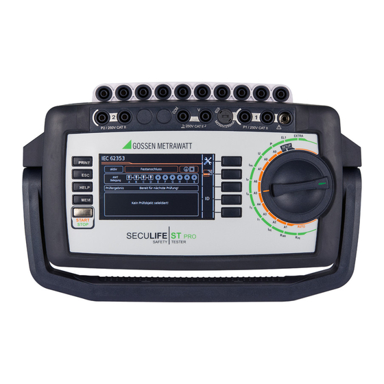
- Page 2 SECULIFE Operating and Connection Overview Operating and Connection Overview Kink protection grommet: black: max. 16 A green: max. 25 A White/silver identified and fused high 2 USB-Master current path – For keyboard AP A ... K Connection for – For scanner Applied parts sockets voltage supply –...
-
Page 3: Table Of Contents
Scope of Delivery Notes on Saving Single Measurements Standard Version (country-specific) and Test Sequences ........10 1 Test instrument SECULIFE ST PRO 1 Mains connection cable Single Measurements ......11 1 Test probe, 2 m, not coiled 8.1 RPE – Protective Conductor Resistance for 1 USB cable, USB A to USB B, length: 1.0 m... -
Page 4: Safety Precautions
SECULIFE Safety Precautions Safety Precautions • Be prepared for the occurrence of unex- pected voltages at devices under test (for SECUTEST BASE(10), SECUTEST PRO and example, capacitors can be dangerously SECULIFE ST BASE(25) test instruments are charged). manufactured and tested in accordance with the following safety regulations: •... - Page 5 SECULIFE Safety Precautions Fuse replacement The test instrument may not be used: The fuses may only be replaced when the • If external damage is apparent, for example instrument is voltage-free, i.e. the instrument if parts which conduct dangerous touch must be disconnected from mains supply voltage are freely accessible, if the display power and may not be connected to a mea-...
-
Page 6: Initial Start-Up
SECULIFE Initial Start-Up Initial Start-Up Detection of Mains Connection Errors The device automatically recognizes mains Mains Connection connection errors if the conditions in the fol- lowing table have been fulfilled. The user is Nominal mains values: 100 to 240 V, 50 Hz to 400 Hz informed of the type of error, and all measuring ➭... -
Page 7: Functions Overview Of Instrument
SECULIFE Scope of Features Functions Overview of Instrument Switch Measuring functions, Switch Measuring functions, setting test current/voltage setting test current/voltage Single measurements, rotary switch level: green P (FT) Function test at the test socket Measurements at voltage-free objects current between L and N voltage between L and N protect. -
Page 8: User Interface Symbols - Parameter And Softkey Symbols
SECULIFE Symbols User Interface Symbols – Parameter and Softkey Symbols Sym- Setup Parameters and their significance bols Page Complete overviews of all symbols are included in the full operating instructions. All measurements: Ref.voltage L-PE: voltage to which the measured values for leakage current have been standardized;... -
Page 9: Internal Database
SECULIFE Database – Keyboard Internal Database Data Input Creation of Test Structures Entry via Touch Screen A complete test structure with data regard- After selecting ID or any other object param- ing customers and devices under test be eter, a keyboard is displayed which allows created in the test instrument. -
Page 10: Notes On Saving Single Measurements And Test Sequences
SECULIFE Saving Notes on Saving Single Measurements and Test Sequences At the end of each test, test results can be Variant 3 – entry of a new ID at the end of the test saved under an ID number which is unequiv- You haven’t yet set up a test structure in the ocally assigned to the respective test object. -
Page 11: Single Measurements
SECULIFE Single Measurements Single Measurements Procedure for measuring with save function and subsequent entry of the (ME) device Any measuring duration is possible. The As an alternative to the procedure described respective measurement is ended by press- above, you can start with step 4 and, after ing START/STOP. -
Page 12: Rpe - Protective Conductor Resistance For Protection Class I Devices
SECULIFE Single Measurements RPE – Protective Conductor Resistance for Protection Class I Devices The selected offset value is permanently stored to memory and adapted for measurements in selector switch position AUTO. Select measuring function Connection also via EL1, VL2E, AT3 adapter, AT16DI/AT32DI Connect DUT Select parameters PE(TS) –... -
Page 13: Rins - Insulation Resistance Measurement For Protection Class I Devices
SECULIFE Single Measurements RINS – Insulation Resistance Measurement for Protection Class I Devices Meas. Parameter Meaning Select measuring function AP on / off Selection: A / B / C / D / E / F / G / H / I / K UINS(set) >... -
Page 14: Rins - Insulation Resistance Measurement For Protection Class Ii Devices
SECULIFE Single Measurements RINS – Insulation Resistance Measurement for Protection Class II Devices Select measuring function Connect DUT – Select parameters P1//PE(TS) ➭ Connect the DUT with the test socket and the applied parts with the applied parts sockets. ➭ Contact all conductive, exposed parts with test probe P1. -
Page 15: Ipe - Protective Conductor Current
SECULIFE Single Measurements IPE – Protective Conductor Current Prior to all leakage current measurements, please make sure that the measurement parameters „Ref. Select Measuring Function voltage L-PE“ and „Testingfreq. Alt“ have been cor- rectly set in the SETUP, see section 10. Connect DUT Select parameters Direct / Diff / Alt... -
Page 16: It - Touch Current
SECULIFE Single Measurements IT – Touch Current Prior to all leakage current measurements, please Select measuring function make sure that the measurement parameters „Ref. voltage L-PE“ and „Testingfreq. Alt“ have been cor- rectly set in the SETUP, see section 10. Connect DUT Select parameters Direct P1/ Diff P1/ Alt P1... -
Page 17: Ie - Device Leakage Current
SECULIFE Single Measurements IE – Device Leakage Current Select measuring function Connect DUT Select parameters Direct / Diff / Alt ➭ Connect the DUT with the test socket and the applied parts with the applied parts sockets. ➭ Contact accessible, conductive parts which are not connected to the protec- tive conductor with test probe P1. -
Page 18: Ia - Leakage Current From The Appl. Part
SECULIFE Single Measurements IA – Leakage Current from the Appl. Part Prior to all leakage current measurements, please make sure that the measurement parameters „Ref. voltage L-PE“ and „Testingfreq. Alt“ have been cor- Select measuring function rectly set in the SETUP, see section 10. Connect DUT Select parameters Direct AP... -
Page 19: Ip - Patient Leakage Current
SECULIFE Single Measurements IP – Patient Leakage Current Prior to all leakage current measurements, please make sure that the measurement parameters „Ref. voltage L-PE“ and „Testingfreq. Alt.“ have been cor- Select measuring function rectly set in the SETUP, see section 10. Connect DUT Select parameters Direct AP... -
Page 20: Ipa - Patient Auxiliary Current
SECULIFE Single Measurements IPA – Patient Auxiliary Current Select measuring function Connect DUT Direct AP Select parameters ➭ Connect the DUT with the test socket and the applied parts with the AP sockets. Special case permanent connection Set parameters Perman. connection AP ➭... -
Page 21: U - Probe Voltage
SECULIFE Single Measurements 8.10 U – Probe Voltage ➭ Connect the DUT to the test socket. ➭ Contact the ungrounded output for pro- Select measuring function tective extra-low voltage with test probe ➭ Select line voltage polarity. Special case: permanently installed DUT Probe Voltage Select parameters PE –... -
Page 22: U - Measuring Voltage
SECULIFE Single Measurements 8.11 U – Measuring Voltage Attention! Only use the enclosed contact pro- Select measuring function tected KS17-ONE measurement cables for the measurement of dangerous voltages please. Special case: permanently installed DUT Meas. Volt. Select parameters V – COM (RMS/AC/DC) ➭... -
Page 23: Ft - Functions Test
SECULIFE Single Measurements 8.12 FT – Functions Test Select measuring function Connect DUT Select parameters ➭ Connect the DUT to the test socket. Starting test Acknowledge line voltage warning Set parameters Meas. Parameter Meaning ➭ Switch DUT on Polarity Phase L – neutral conductor N Save measured values to clipboard Neutral conductor N –... -
Page 24: El1 - Function Testing Of Extension Cords
SECULIFE Single Measurements 8.13 EL1 – Function Testing of Extension Cords Select measuring function Connect DUT EL1-Adapter Select parameters Test Socket – P1 VL2E-adapter Connection of EL1 Adapter Set parameters ➭ Connect the EL1 adapter to the P1 Meas. Parameter Testing for probe sockets at the test instrument. -
Page 25: Extra - Special Functions
SECULIFE Single Measurements 8.14 EXTRA – Special functions Temp. – Temperature measurement Select measuring function EXTRA Additional measurement functions are assigned to rotary switch position EXTRA. Temp., Current (clip) or PRCD break time Connect DUT ➭ Select the desired measuring function. V –... - Page 26 SECULIFE Single Measurements IZ – Current clamp measurement tA – PRCD Time to Trip (portable residual current device) Connect DUT Connect DUT V – COM (AC) (w. Mains) ➭ Connect the PRCD to the test socket. Set parameters Start test (test current 30 mA) Meas.
-
Page 27: P2 Test Probes
SECULIFE Single Measurements 8.15 2-Pole Measurements with P1 & P2 8.16 Measurement with Current Clamp Sensor at Test Probes Permanently Installed DUTs of Safety Class I In case your DUT is not equipped with a SECUTEST PRO and SECULIFE ST BASE(25) only country-specific mains plug that fits into the SECUTEST PRO Clamp... -
Page 28: Measurements With Test Adapter
SECULIFE Single Measurements 8.17 Measurements with Test Adapter Connection Example with EL1 Test with Adapter EL1 VL2E AT3- AT16DI CEE- IIIE AT32DI Adapter EL1 adapter DUT terminals ✔ ✔ Inlet plug 1P+N+PE 16 A — — — ✔ Schuko 1P+N+PE 16 A —... -
Page 29: Test Sequences In Accordansce With Standards
SECULIFE Test Sequences in Accordance with Standards Test Sequences in Accordance 9 At the end of the test sequence, you can generate a list of the with Standards results of the individual test steps. If the same sequence of single tests will be 10 If you want to view details such as run frequently (one after the other with sub- the settings for the individual test... -
Page 30: Sample Test Sequence
SECULIFE Test Sequences in Accordance with Standards Sample Test Sequence Sequence parameters Select test sequence Individual test steps can be configured with the sequence parameters, see detailed operating instructions. Set classification parameters Switch setting: A1 ... A9 Meas. Parameter Meaning As-delivered Condition (KA00): Standard Test standard / extension cord... - Page 31 SECULIFE Test Sequences in Accordance with Standards Selection of Applied Parts (APs) Connect DUT ➭ Connect the DUT to the test instrument in ac- cordance with the selected test sequence. – Test socket – Permanent connection – Adapter ➭ Connect the applied parts with the AP sockets.
- Page 32 SECULIFE Test Sequences in Accordance with Standards Manual evaluation of visual inspection Test step – automatic evaluation Visual inspection passed The measured value is ascertained automat- ically within a specified period of time. The test sequence is then automatically Visual inspection not passed resumed.
- Page 33 SECULIFE Test Sequences in Accordance with Standards Optional test step Optional test step End of sequence – display results Confirm results (display of the memory screen depends on the parameter pre-selection in the SETUP switch po- Switch to memory screen sition: Setup 1/3 >...
-
Page 34: Parameters For Individual Measurements And Test Sequences
Measurement Parameters SECULIFE SETUP Parameters for Individual Mea- Repair and Replacement Parts Service surements and Test Sequences Calibration Center and Rental Instrument Service Measurement parameters which apply for both individual measurements and test If required please contact: sequences, have to be entered in selector switch position SETUP. -
Page 35: Declaration Of Conformity
Declaration of Conformity SECULIFE Declaration of Conformity GMC-I Messtechnik GmbH... -
Page 36: Database Software
SECULIFE Addresses / Database Software Database Software IZYTRONIQ is a test software that has been newly developed from scratch. It enables the user to visualize and manage the entire test- ing procedure for all our test instruments and to document it in an audit-proof manner. For the first time, it is thus possible to com- bine the test and measurement data from a great variety of test instruments and multi-...
Need help?
Do you have a question about the SECULIFE ST PRO and is the answer not in the manual?
Questions and answers