
Related Manuals for Gossen MetraWatt METRAHIT IM XTRA


Summary of Contents for Gossen MetraWatt METRAHIT IM XTRA
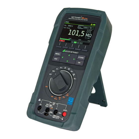
- Page 1 Operating Instructions METRAHITIM (M273A/D/W) & METRAHITIM (M274A/B) XTRA DRIVE Insulation Tester, Milliohmmeter, TRMS Multimeter, Short-Circuited Coil Tester 3-447-035-03 6/10.19...
- Page 2 TRMS (Ri 9 M) filter 1kHz AC+DC TRMS (Ri 1 M) 1 Type KC4 Kelvin clip (1 pair with METRAHIT IM XTRA) ✔ AC+DC range (interference voltage) 1 Type KC27 Kelvin probe (with METRAHIT IM E-DRIVE only) Hz (V ...
-
Page 3: Table Of Contents
Contents Page Contents Page Addresses ................. 4 6.6.4 Direct and Pulsating Voltage Measurement, V DC and V (AC+DC) .. 30 Resistance Measurement “” ..........31 Product Support ................4 Capacitance Measurement F ..........32 Recalibration Service ..............4 Temperature Measurement with Resistance Thermometer – Repair and Replacement Parts Service Temp RTD ................ -
Page 4: Addresses
Addresses Repair and Replacement Parts Service Calibration Center* and Rental Instrument Service Product Support If required please contact: Technical Queries (use, operation, software registration) GMC-I Service GmbH Service Center If required please contact: Beuthener Straße 41 90471 Nürnberg, Germany GMC-I Messtechnik GmbH Phone: +49-911-817718-0 Product Support Hotline Fax:... -
Page 5: Safety Features And Precautions
Safety Features and Precautions • No measurements may be made with this instrument in elec- trical circuits with corona discharge (high-voltage). You have selected an instrument which provides you with high • Special care is required when measurements are made in HF levels of safety. -
Page 6: Use For Intended Purpose
Use for Intended Purpose Meanings of Danger Symbols • The multimeter is a portable device which can be held in the hand during the performance of measurements. Warning concerning a point of danger • Only those types of measurements described in chapter 6 (attention, observe documentation!) may be performed with the measuring instrument. -
Page 7: Operating Overview
Operating Overview Symbols Used in the Digital Display Connections, Keys, Rotary Switch, Symbols Chapter 9.2 Chapter 4.4.4 Chapter 3.2 Chapter 3.4 Chapter 5.6 Chapter 3.3 Charge Levels Battery full Battery weak Battery OK Battery (almost) dead, U < 3.3 V Chapter 3.5 Max. -
Page 8: Symbols Used For Rotary Switch Positions
Symbols Used for Rotary Switch Positions Additional Current Clamp Sensor Function Clip = 1:1/10/100/1000 Switches FUNC Display Measuring Function (via the “Setup for currently selected measurement” menu) RISO RISO M Insulation resistance measurement Uext Pulsating voltage, TRMS DC + AC, 15 Hz ... 500 Hz, only for detection of interference voltage! (before starting measurement) Uset... -
Page 9: Initial Startup
Initial Startup 4.4.2 Language >German/English – Selecting the User Interface Language Battery Pack ➭ Press the MENU key. Be certain to refer to Chapter 9.2 regarding correct installation of the battery ➭ Press the General Setup softkey. pack! ➭ Select the Language parameter with the help of the ... -
Page 10: System > Display Zeros
4.4.5 System > Display Zeros Entering the Old Password The Display Zeros parameter can be used to specify whether lead- ing zeros will appear or be suppressed at the measured value dis- > General Setup System MENU play. -
Page 11: System > Default Settings
4.4.8 System > Default Settings Switching the Instrument Off All of the settings which you have changed can be returned to Switching the Instrument Off Manually their default settings here. The following warning appears after ➭ The instrument is switched off automatically by setting the ro- pressing the OK button: “Reset?”. -
Page 12: Control Functions
Control Functions Help The following information can be displayed for switch positions and basic functions after they have been selected with the rotary selector switch: • Explanation of the measurement • Measuring ranges • Wiring diagram ➭ Press the MENU key to this end. ➭... -
Page 13: Selecting Measuring Functions And Measuring Ranges
Selecting Measuring Functions and Measuring Ranges Zero Offset / Relative Measurements Zero offset or a reference value for relative measurements can be 5.2.1 Automatic Range Selection stored to memory depending upon deviation from the zero point: The multimeter is equipped with auto-ranging for all measuring functions except for temperature measurement, as well as diode Deviation from zero point Display... -
Page 14: Display (Tft)
Display (TFT) 5.4.1 Digital Display Measured Value, Unit of Measure, Type of Current, Polarity The measured value with decimal and plus or minus sign appears at the digital display. The selected unit of measure and current type are displayed as well. A minus sign appears to the left of the value during the measurement of zero-frequency quantities, if the plus pole of the measured quantity is applied to the “”... -
Page 15: Measured Value Storage - Data Function (Auto-Hold/Compare)
Measured Value Storage – Data Function (auto-hold/compare) Condition Response from Instrument General Function Data / Min- Display Meas. Measuring Acous- Data An individual measured value can be automatically “frozen” with Function Signal Data + MV the DATA function (auto-hold). Activate Short displayed Applications... -
Page 16: Saving Minimum And Maximum Values - "Minmax
5.5.1 Saving Minimum and Maximum Values – “MinMax” Measured Value Memory – STORE Function. The following options are available for the storage of measured General values: Minimum and maximum measured values applied to the measur- • Store at instrument by pressing the STORE key on the instru- ing instrument’s input after the MinMax function has been acti- ment vated can be “frozen”... -
Page 17: Measurement Data Recording
Measurement Data Recording Setting the Record Type In this menu, you can choose between a definable periodic and fixed sampling rate (parameter Periodic) and a one-off storage of a data value by means of the STORE key (parameter Data Value). ➭... - Page 18 Setting Hysteresis threshold above this measuring range limit does not make sense. It’s thus advisable to perform measurement with a fixed measur- The hysteresis setting allows for efficient use of memory space. ing range. During memory mode operation, new measured data are only saved if they deviate from the previously stored value by an Actual measurement is always executed using the selected sam- amount which exceeds the selected hysteresis value.
- Page 19 Creating Groups Ending Recording Groups can be created here in order to be able to sort measured Proceed as follows in order to stop recording: values when they’re saved. As is also the case when the pass- ➭ Press the MENU key. word is changed, entries are made using a keyboard which ap- ➭...
-
Page 20: Measurements
Measurements Insulation Resistance Measurement – RISO Function 6.2.1 Preparing for Measurement Enabling Parameter Changes A password must be entered in order to adjust the parameters for Note each of the following measurements: Checking the Measurement Cables • RISO: change test voltage The test probes at the ends of the measurement cables should be short circuited before performing insulation •... -
Page 21: Performing Insulation Measurement
6.2.2 Performing Insulation Measurement ➭ When the device under test is voltage-free, activate the mea- Caution: High-Voltage! Do not touch the conductive ends of the test probes when the surement by pressing the Start softkey on the instrument or on instrument has been activated for the measurement of insulation the probe. -
Page 22: Short-Circuited Coil Measurement - Coil Function
Short-Circuited Coil Measurement – COIL Function In combination with the optional COIL TEST ADAPTER, short-cir- RISO cuited coil measurements with a test voltage of 1000 V are possi- ble within an inductance range of 10 μH to 50 mH at 100 Hz. This range corresponds to motors in accordance with DIN standards with power ratings of roughly 15 kVA to 80 MVA. -
Page 23: Conducting The Short-Circuited Coil Measurement
6.3.2 Conducting the Short-Circuited Coil Measurement Note ➭ Contact the desired coil (e.g. U–V) in order to test for absence The “RISO” or “COIL” switch position may only be used for of voltage. short-circuited coil detection. However, if interference voltage is inadvertently applied with the switch in this position, it appears at the display. -
Page 24: Ending The Measurement And Discharging
6.3.3 Ending the Measurement and Discharging ➭ End the respective measurement by pressing the Stop softkey. After ending the measurement, any remaining re- Discharge sidual voltage (Uext) is displayed (message: „Discharge ...“), which may result from cable ca- pacitance. The instrument’s internal 1 M resis- tor causes rapid discharging. -
Page 25: Absorption Index Measurement - Dar
Absorption Index Measurement – DAR The absorption index test is part of the polarization index test (PI). RISO Insulation resistance measurements are placed in relationship to one another after 30 and 60 seconds. Application: faster version of the polarization index test. RISO COIL ➭... -
Page 26: Polarization Index Measurement - Pi
Polarization Index Measurement – PI After measurement has been completed, any Discharge remaining residual voltage U is displayed which Polarization index testing is recommended for electric machines. may result from cable capacitance and a capaci- This procedure involves expanded testing of insulation resistance. tive device under test. -
Page 27: Voltage Measurement
Voltage Measurement Notes Regarding Voltage Measurement • The multimeter may only be operated with installed rechargeable batteries or mains module. Dangerous voltages are otherwise not indicated, and the instrument may be damaged. • The multimeter may only be operated by persons who are capable of recognizing touch hazards and taking the appropri- ate safety precautions. -
Page 28: Alternating Voltage And Frequency Measurement V Ac And Hz With Selectable Low-Pass Filter
6.6.1 Alternating Voltage and Frequency Measurement V AC and Hz with Selectable Low-Pass Filter ➭ In accordance with the voltage or frequency to be measured, turn the rotary switch to V~ or Hz. ➭ Press the MENU key. ➭ Press the “Setup for currently selected measurement” softkey. ➭... -
Page 29: Duty Cycle Measurement - Duty Ac
6.6.2 Duty Cycle Measurement – Duty AC The pulse-period ratio can be ascertained for square-wave sig- nals with the duty cycle measurement. ➭ Set the rotary switch to V~. ➭ Repeatedly press the Func softkey until Duty AC appears at the display. -
Page 30: Direct And Pulsating Voltage Measurement, V Dc And V (Ac+Dc)
6.6.4 Direct and Pulsating Voltage Measurement, V DC and V (AC+DC) ➭ Set the rotary switch to V or V . ➭ Press the MENU key. ➭ Press the “Setup for currently selected measurement” softkey. ➭ Make sure that the Clip parameter is set to Off. Otherwise all measured values are displayed in amperes, corrected by the amount resulting from the selected transformation ratio for an interconnected current clamp sensor. -
Page 31: Resistance Measurement
Resistance Measurement “” ➭ Disconnect supply power from the electrical circuit of the de- vice to be measured, and discharge all high-voltage capaci- tors. ➭ Make sure that the device under test is voltage-free. Interfer- ence voltages distort measurement results! Refer to Chapter 6.6.4 regarding testing for the absence of voltage with the help of the direct voltage measurement. -
Page 32: Capacitance Measurement F
Capacitance Measurement F ➭ Disconnect supply power from the electrical circuit of the de- vice to be measured, and discharge all high-voltage capaci- tors. ➭ Make sure that the device under test is voltage-free. Capacitors must always be discharged before measurement is performed. -
Page 33: Temperature Measurement With Resistance Thermometer - Temp Rtd
Temperature Measurement with Resistance Thermometer – Temp RTD Temperature measurement is performed with a Pt100 or Pt1000 resistance thermometer (accessory, not included), which is con- nected to the voltage input. ➭ Set the rotary switch to “” or “Temp”. ➭... -
Page 34: Temperature Measurement With Thermocouple - Temp Tc
6.10 Temperature Measurement with Thermocouple – Temp Temperature measurement is performed with a type K thermo- couple (accessory, not included), which is connected to the volt- age input. ➭ Set the rotary switch to “” or “Temp”. ➭ Repeatedly press the Func softkey until the Temp TC measuring function is displayed. -
Page 35: Continuity Test
6.11 Continuity Test 6.12 Diode Testing with Constant Current of 1 mA ➭ Disconnect supply power from the electrical circuit of the de- ➭ Disconnect supply power from the electrical circuit of the de- vice to be measured, and discharge all high-voltage capaci- vice to be measured, and discharge all high-voltage capaci- tors. -
Page 36: Milliohm Measurement - Rlo (2-Wire Measurement)
6.13 Milliohm Measurement – Rlo (2-wire measurement) ➭ Disconnect supply power from the electrical circuit of the de- vice to be measured, and discharge all high-voltage capaci- tors. ➭ Make sure that the device under test is voltage-free. Interfer- ence voltages distort measurement results! Refer to Chapter 6.6.4 regarding testing for the absence of voltage with the help of the direct voltage measurement. -
Page 37: Milliohm Measurement - M/4 (4-Wire Measurement)
6.14 Milliohm Measurement – m/4 (4-wire measurement) 6.14.1 Compensation of Cable Resistance m Electrical resistance is a dipole which can generally only be mea- sured using two poles. This is accomplished by directing a mea- suring current of predetermined magnitude through the device under test and measuring the resultant voltage drop. -
Page 38: Milliohm Measurement With 200 Ma Or 20 Ma Dc [M]
6.14.3 Milliohm Measurement with 200 mA or 20 mA DC [m] 6.14.4 Milliohm Measurement with 1 A Pulsating Measuring Cur- rent (automatic thermovoltage correction at 3 300 m) ➭ Make sure that the device under test is voltage-free (see ➭... -
Page 39: Current Measurement
6.15 Current Measurement Notes Regarding Current Measurement • The multimeter may only be operated with installed rechargeable battery pack or mains module. Dangerous currents are otherwise not indicated, and the instrument may be damaged. • Set up the measuring circuit in a mechanically secure fashion, and secure it against inadvertent breaks. -
Page 40: Direct And Pulsating Current Measurement, Direct Connection, - A Dc And A (Ac+Dc)
6.15.1 Direct and Pulsating Current Measurement, Direct Connec- tion, – A DC and A (AC+DC) ➭ First disconnect supply power from the measuring circuit or the power consumer (1), and discharge any capacitors. ➭ Set the rotary switch to A ➭... -
Page 41: Alternating Current And Frequency Measurement, Direct Connection, - Aac And Hz
6.15.2 Alternating Current and Frequency Measurement, Direct Connection, – AAC and Hz ➭ First disconnect supply power from the measuring circuit or the power consumer (1), and discharge any capacitors. ➭ Set the rotary switch to A ➭ Repeatedly press the Func softkey until the desired measuring function is displayed. -
Page 42: Direct And Pulsating Current Measurement With Current Clamp Sensor - Adc And A (Ac+Dc)
6.15.3 Direct and Pulsating Current Measurement with Current Clamp Sensor – ADC and A (AC+DC) Voltage/Current Transformer Output When a current clamp sensor is connected to the multimeter (V input), all current displays appear with the correct value in accordance with the selected transformation ratio. The only pre- requisite is that the current sensor is equipped with at least one of A DC the below listed transformation ratios, and that the ratio has been... -
Page 43: Alternating Current Measurement With Current Clamp Sensor - Aac And Hz
➭ The correction or offset value is deleted by pressing Zero, by 6.15.4 Alternating Current Measurement with Current Clamp Sen- sor – AAC and Hz changing to another measuring function or by switching the in- strument off. The value is cleared from the display. Voltage/Current Transformer Output When a current clamp sensor is connected to the multimeter (V input), all current displays appear with the correct value in... -
Page 44: Measuring Sequences
6.16 Measuring Sequences Creating a New Measuring Sequence If the same sequence of single measurements will be run fre- quently (one after the other with subsequent report generation), it’s advisable to make use of measuring sequences. Up to 10 measuring steps can be created for each measuring sequence. - Page 45 Running a Measuring Sequence Overview of the Meanings of Softkeys and Hard Keys Meaning Softkeys SEQ Name Enter or change the name of a measuring sequence* Ins Function Insert a measuring step above the selected line with measuring function Ins Check Insert a measuring step above the selected line with measuring instruc- tions Delete...
-
Page 46: Interface Operation
PC (operat- ing systems as of Android 2.3.3). In the case of the METRAHIT IM XTRA BT (M273D) and the METRAHIT IM E-DRIVE BT (M274B), wireless transmission is possible via Blue- tooth to a PC, as well as to a smartphone or a tablet PC (Android). -
Page 47: Characteristic Values
Characteristic Values Mea- Intrinsic Uncertainty at Reference Conditions Resolution at Overload suring (... % rdg. + ... d) Input impedance Upper Range Limit Capacity Func- Measuring Range 30,000 3,000 30,000 30,000 tion 1, 11 1, 11 Value Time 30,000 3,000 (input) 10 V 300 mV... - Page 48 Insulation Measurement Frequency Influence for V Voltage Ranges AC+DC Intrinsic Uncer- Deviation Nominal Voltage tainty at Reference Measuring Range Resolution 300 mV range 3 V, 30 V, 300 V range 1000 V range Conditions Frequency Range ± (... % rdg. + ... digits) ±...
- Page 49 Display Power Supply TFT color graphic display (55 x 36 mm) with analog and digital Battery pack 3.7 V, 4000 mAh, LiPo display including unit of measure, type of current and various spe- (approx. 25% self-discharging per year) cial functions Service life Approx.
- Page 50 Data Interface Type Bluetooth 4.2 Frequency band 2.402 ... 2.480 GHz Transmitting power Max. 91 mW Functions – Query measuring functions and parameters – Query momentary measurement data Internal Measured Value Storage Memory capacity 64 MBit for approx. 300,000 measured values with indication of date and time Mechanical Design Housing...
-
Page 51: Maintenance And Calibration
Maintenance and Calibration Removing the Battery Pack Note Note Recommendation: Recommendation: Turn the rotary switch to the OFF position and disconnect Disconnect the instrument from the measuring circuit the instrument from the measuring circuit before remov- before removing the battery pack or the mains module! ing the battery pack or the mains module! Attention! ➭... -
Page 52: Fuse
Fuse Housing Maintenance No special maintenance is required for the housing. Keep outside Testing the Fuse surfaces clean. Use a slightly dampened cloth for cleaning. In par- The fuse is tested automatically: ticular for the protective rubber surfaces, we recommend a moist, •... -
Page 53: Recalibration
PRODUCTS Measuring Technology – Portable – Multimeters val of once every 2 to 3 years is sufficient as a rule. Specialized Applications METRAHIT IM XTRA ... Accessories). During recalibration* at an accredited calibration laboratory (DIN EN ISO/IEC 17025), deviations from traceable standards 10.2... -
Page 54: Index
Index Clearing Memory ..................19 Absorption Index Measurement ................25 Creating Groups ..................19 Accessories ......................2, 53 Ending Recording ..................19 Addresses ......................4 Querying Occupancy .................19 Automatic Shutdown Setting Hysteresis ..................18 Specifying a Time ..................11 Setting the Recording Type ..............17 AUTO-Range Function ..................13 Setting the Sampling Rate ................17 Start Recording... - Page 55 Temperature Measurement With Thermocouples ................. 34 Test Sequences ....................44 Use for Intended Purpose ..................5 Use of KS17-2 and Z270S ..................53 Voltage Comparator .................28, 29, 30 Voltage Measurement Notes ......................27 WEEE Mark ......................8 GMC-I Messtechnik GmbH...
- Page 56 Edited in Germany • Subject to change without notice • PDF version available on the Internet Phone: +49-911-8602-111 GMC-I Messtechnik GmbH Fax: +49 911 8602-777 Südwestpark 15 E-mail info@gossenmetrawatt.com 90449 Nürnberg Germany www.gossenmetrawatt.com •...
Need help?
Do you have a question about the METRAHIT IM XTRA and is the answer not in the manual?
Questions and answers