
Related Manuals for Gossen MetraWatt SECULIFE ST PRO


Summary of Contents for Gossen MetraWatt SECULIFE ST PRO
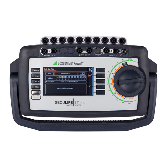
- Page 1 Operating Instructions SECULIFE Instrument for Testing the Electrical Safety 3-447-032-03 of Electrical (Medical) Devices 1/7.19...
- Page 2 Controls Probe Type Applications Display of symbols for Strain relief, black Test current: 200 mA / devices connected to the White/silver 10 A, max. 16 A USB master interface (see below) identified SK2-25A (Z746C) Test current: 200 mA / Strain relief, green 25 A, max.
- Page 3 Connections 13, 14 Meaning Applied part sockets A to K test probe P2 for 2-pole measurement Voltage measuring inputs (COM-V) Fuse link for probe input P1 Test probe connection (P1) Connection (jack socket) for supplying power to the SECUTEST CLIP (Z745H) (see also operating instructions for leakage current clamp meter) Country-specific standard socket (test socket) for connecting devices under test...
- Page 4 Direct voltage component Standard Version (country-specific) Measuring voltage, RMS V – COM Alternating voltage component 1 Test instrument SECULIFE ST PRO section V – COM (TS on) Direct voltage component 1 Mains power cable Function test at the test socket...
-
Page 5: Table Of Contents
Contents Page Page Applications ..............6 Notes on Saving Single Measurements and Test Sequences .. 27 Table: Types of DUTs – Tests – Standards ........6 QuickEdit Function – QEDIT Table: Single Measurements – Standards ........6 (feature KD01, “Z853S – SECUTEST DB COMFORT”) ....27 Safety Features and Precautions ........ -
Page 6: Applications
14.6 Entry via External USB Keyboard ..........109 Repair and Replacement Parts Service 14.6.1 Additional Key Functions Calibration Center and Rental Instrument (Feature KD01, “Z853S – SECUTEST DB COMFORT”) ....109 Service ................. 113 14.7 Classification of DUTs ..............109 14.7.1 Protection Classes ..............109 Product Support ............ -
Page 7: Safety Features And Precautions
Safety Features and Precautions Attention! The test instrument fulfills all requirements of applicable EU direc- tives and national regulations. We confirm this with the CE mark. If the fuse at test probe P1 is defective after testing has The relevant declaration of conformity can be obtained from been started, all subsequent measurements conducted GMC-I Messtechnik GmbH. -
Page 8: Test Instructions For Applied Parts Measuring Functions
➭ This measurement must be repeated for all 10 APP sockets. ➭ Start the “IA Direct APP” measurement. ➭ Stop the “IP Direct APP” measurement. ➭ The SECULIFE ST PRO should indicate approximately 1 mA. ➭ If a significantly lower value is displayed, start the measure- Testing the Isolating Function ment again with reversed mains polarity. - Page 9 Meanings of Symbols on the Instrument The symbols on the instrument have the following meanings: Attention! Dangerous Voltage at Connections or Contacts Warning regarding dangerous electrical voltage When conducting measurements at APP sockets, APP sockets are connected together for the purpose of mea- surement or grounding depending on the selected set- Warning concerning a point of danger tings at the test instrument, in the automatic sequences...
-
Page 10: General Operation
General Operation Note We’re unable to offer any guarantees regarding the use of Measured Value Display scanning devices other than those listed in the appendix. The following items appear at the display panel: • The selected measuring function or standard Reading in an RFID Code •... -
Page 11: Test Report Settings In Setup
➭ By viewing the printer information you can determine whether 3.5.3 Test Report Settings in SETUP or not the connected barcode printer is correctly recognized The following settings can be entered with the switch in the by the test instrument: SETUP position in menu 2/3 after opening the test reports menu: Setup (2/3) >... -
Page 12: Initial Startup
Initial Startup 4.1.1 Measurements in IT Systems (new parameter as of firmware 1.5.0) Connecting the Test Instrument to the Mains The IT system ➭ See section 12 for nominal mains values (nominal ranges of setting can be use). activated for all ➭... -
Page 13: Automatic Recognition Of Mains Connection Errors
4.1.2 Automatic Recognition of Mains Connection Errors Connecting Test Probe P1 or P2 Insert the double plug from test probe P1 or P2 into socket 1 or 2 The device automatically recognizes mains connection errors if respectively such that the plug with the white ring makes contact the conditions in the following table have been fulfilled. -
Page 14: Device Settings
Device Settings Setup 2/3 > Culture > Language (for user interface) Setup 2/3 > Culture > Keyboard Layout (for alphanumeric entries) Setup Setup 1/3 > System > Date / Time (for report generation) For the purpose of initial start-up, we recommend setting the following basic parameters in the order Setup 1/3 >... - Page 15 Setup 1/3 > System 1/2 Menu selection for operating parameters, page 1 of 2 PRINT Page 2/2 Select language for user interface and keyboard See settings menu below Date and time setting menu HELP See settings menu below Enable functions, display extras Reset to default values Caution: The Setup configurations are deleted! (also deletes list of inspectors,...
- Page 16 Database Functions Setup 1/3 PRINT HELP Setup 1/3 > Database 1/2 Menu selection for database functions, page 1 of 2 PRINT Display additional menu pages Delete database content (but not its structure) Note: Data are irretrievably deleted! HELP Display database statistics Only with inserted USB drive: Backup database to USB flash drive ( formatted)
- Page 17 Printer Functions – Selection and Settings Using the Thermal Printer as an Example Setup 2/3 > Printer Selecting the connected printer PRINT Z721S printer: printer info / printer settings Z721D * printer: printer info / printer settings HELP * Phase-out model Z721E * printer: barcode label printer, printer info / printer settings * For testing instrument firmware as of 1.8.3...
-
Page 18: Internal Database
Internal Database Note Data transfer to the PC should not be started during sin- Creating Test Structures, General gle measurements or test sequences. A complete test structure with data regarding customer proper- ties, buildings, floors, rooms and test objects can be created in 5.2.1 Export –... - Page 19 Test Structure – Hierarchy of Object Levels in Devices with Database Extension, Feature KB01, “Z853R – SECUTEST DB+” Location MEM Database Property Designation ZIP code Building Designation City Street Floor Designation Room Designation Test interval * Comment No. of type B APPs Cost center Mains conn.
-
Page 20: Switching Between 2 Tree Structure Views (At Devices With Database Extension, Feature Kb01, "Z853R - Secutest Db+")
Test Structure, Customer View – Hierarchy of Object Levels or in Devices with Database Extension, Feature KB01, “Z853R – SECUTEST DB+” Customer MEM Database ZIP code Customer Designation City Street Test interval * Comment No. of type B APPs ** Cost center Mains connection ** Device... -
Page 21: Data Entry
Data Entry Overview of Keyboard Entries via the Touchscreen Keyboard (feature E01) ➭ Briefly pressing the shift key once causes the next char- * Also via assigned softkey acter to appear in upper- case. Display Panel ➭ Pressing the shift key for a longer period of time Delete characters from right * causes all following charac-... -
Page 22: Creating A Test Structure In The Test Instrument, Navigating Within The Structure And Displaying Measured Values
Creating a Test Structure in the Test Instrument, Navigating within the Structure and Displaying Measured Values Overview of the Meanings of the Symbols for Creating Objects – Navigation within Test Structures MEM 1/3 Object selection menu – page 1/3 Scroll to next menu (page 2/3) PRINT Select customers or devices Select customers or devices... -
Page 23: General Procedure For Creating Test Structures
➭ Now select the position with the scroll keys to which the ob- 5.4.1 General Procedure for Creating Test Structures ject will be moved. After selection with the MEM key, all setting options for the cre- ➭ The display is automatically returned to the initial window after ation of a tree structure are made available on three menu pages confirming with the green checkmark. -
Page 24: Searching For Structure Elements
5.4.2 Searching for Structure Elements ➭ Scroll to the first menu page (MEM 1/3) with the help of the key. ➭ Scroll to the third menu page (MEM 3/3) with the help of the key. ➭ Press the text symbol in order to search for text. ➭... -
Page 25: Connecting The Device Under Test
Connecting the Device Under Test Specifying an Alternative Test Frequency Selectable frequency setpoint value for synthetic test voltage for ➭ Connect the DUT in accordance with the schematic diagrams all leakage current measurements of measurement type “Alterna- included in the online help function. tive”, affecting the following measurements and/or rotary selector switch positions: Connection of the DUT to the test instrument depends on:... -
Page 26: Special Conditions
Special Conditions • DUT connection detection (only with country-specific variant *) With the rotary switch in the A1-A9 position, the “Test Socket” Note connection type is selected automatically (if correspondingly configured), if a mains plug is detected in the test socket. Protection Class II Devices with Protection Class I Mains Plugs If the device under test is equipped with a protection •... -
Page 27: Notes On Saving Single Measurements And Test Sequences
Notes on Saving Single Measurements and Test If the searched for ID isn’t found, the following question appears. Sequences When creating a new object you can first of all choose between a (standard) test object ( icon) or a medical test object – “new At the end of each test, test results can be saved under an ID ME equipment”... -
Page 28: Single Measurements
Single Measurements • Checking is performed before each measurement in order to assure a trouble-free sequence, and to prevent any damage to the DUT. General • Single measurements can be saved to memory. The assign- ment of an ID number is possible to this end. •... -
Page 29: Meaning Of Symbols In The User Interface
Meaning of Symbols in the User Interface Measurement Series and Storage Single measurements can be combined into measurement series. Sym- Softkey Variants, Single Measurements The measured values can be saved by pressing the save key, or measurement series can be generated. These can be saved to a Set parameters test object (ID number) which has already been set up in the data- base (see section 5.4.1). - Page 30 Note Measurements and measurement series can only be saved after measurement has been completed. Mea- sured values can only be added to intermediate buffer memory during a measurement. Customer, location and other entries cannot be changed in the memory menu. These have to be selected directly in the database and entered or changed.
-
Page 31: Measuring Protective Conductor Resistance - Rpe
Measuring Protective Conductor Resistance – RPE Wiring Diagram Single measurements, rotary switch level: green Measurement of RPE at Single-Phase Extension Cords with EL1 Measure- Measure- Measuring Functions – Measurement type PE(TS) - P1 (passive) ment Type ment Type Protective conductor resistance –... - Page 32 Wiring Diagram Wiring Diagram Setting Measuring Range at the Clamp and Parameters at the Test Protection Class I Devices Instrument Special Case: Permanently Installed DUTs This measurement type can only be selected if test current is set – Measurement type PE(mains) - P1 to 10 A AC.
- Page 33 Setting Measuring Parameters for RPE Protective Conductor Measurement with 25 A AC (feature G02) In accordance with IEC 60601, at least 25 A must be achieved with a load of 0.1 Ω and a maximum voltage of 0.6 V. Measuring Meaning Parameter Continuous protective conductor resistance measurement with a...
- Page 34 Test Sequence with Connection to the Test Socket Special Case: Testing Protective Conductor Resistance at PRCDs ➭ Set the rotary switch to the R For PRCDs whose protective conductor resistance cannot be position. measured when switched off, the test instrument offers the ➭...
-
Page 35: Insulation Resistance Measurement - Rins
Insulation Resistance Measurement – RINS Protection Class II Devices with Exposed Conductive Parts – Measurement type LN(TS) - P1 – DUT mains plug to test socket – Test probe P1 to P1 terminals Schematic Diagram Single measurements, rotary switch level: green Measuring Functions Measurement Type... - Page 36 Wiring Diagram Protection Class I Devices with Outputs for Safety Extra-Low Voltage and Exposed Conductive Parts – Measurement type LN(TS) - P1 – DUT mains plug to test socket – Test probe P1 to P1 terminals Schematic Diagram Special Case: Permanently Installed Protection Class I Devices –...
- Page 37 Protection Class I Devices Protection Class I Devices with Terminals for Applied Parts with Exposed Conductive Parts – Measurement type PE(TS) - P1 – Measurement type LN(TS) - P1//PE(TS) – DUT mains plug to test socket – DUT mains plug to test socket –...
- Page 38 Protection Class I Devices Protection Class I Devices with Terminals for Applied Parts with Terminals for Applied Parts – Measurement type PE(mains) - APP – Measurement type P1 // PE(TS) – APP – DUT mains plug to test socket – DUT mains plug to test socket –...
- Page 39 Setting Measuring Parameters for RINS Test Sequence Measuring Meaning Parameter Attention! Measurement Type Suitable for Prerequisite for Testing DUT Connection via The measurement of insulation resistance may not be conducted on protection class I devices which have not LN(TS)-PE(TS) PC I: Testing is conducted be- Test socket, EL1, VL2E, passed the protective conductor resistance test.
-
Page 40: Measuring Leakage Current
Measuring Leakage Current Attention! Removing the Connector Cable Attention! Do not remove the DUT’s connector cable until the test Measurement with DUT Connected to Line Voltage has been stopped, in order to assure that the capacitors It’s absolutely essential to assure that the device under have been discharged. -
Page 41: Protective Conductor Current - Ipe
8.7.1 Protective Conductor Current – IPE ing (which are connected to each other). Current which flows over the insulation at the device under test is measured. Protective Conductor Current Measuring Method (direct measure- ment) The device under test is operated with mains power. Current which flows through the PE conductor to earth at the mains side of the device connection is measured. - Page 42 Wiring Diagram Wiring Diagram (AT3-IIIE probe to COM-V) Alternative Measuring Method (equivalent leakage current) Measurement of Protective Conductor Current via Current Clamp – Alternative measurement type Sensor with Voltage Output for Permanently Installed DUTs – DUT mains plug (protection class I) to test socket (only with feature I01 with optional current clamp sensor) –...
- Page 43 Setting Measuring Parameters for IPE Test Sequence for Direct Measuring Method ➭ Before conducting any leakage current measurements, make Measuring Meaning sure that the “Ref. voltage L-PE” and “Alt. Test Freq.” mea- Parameter surement parameters have been correctly set in SETUP (see section 6.2).
- Page 44 Test Sequence with Differential Current Method Maximum Permissible Limit Values for Leakage Current in mA ➭ Before conducting any leakage current measurements, make Test Standard sure that the “Ref. voltage L-PE” and “Alt. Test Freq.” mea- PC I: 3.5 VDE 0701-0702:2008 surement parameters have been correctly set in SETUP (see 1 mA/kW * section 6.2).
-
Page 45: Touch Current - It
8.7.2 Touch Current – IT Wiring Diagram Note Single measurements, rotary switch level: green Regarding protection class I DUTs: Measure- Measure- Measuring Functions Parts may or may not be grounded. ment Type ment Type With Mains Without Coincidental grounding only occurs in the event of an to Test Mains error. - Page 46 Differential Current Method Alternative Measuring Method (equivalent leakage current) – Measurement type differential P1 – Measurement type alternative P1 – DUT mains plug to test socket – DUT mains plug to test socket – Test probe P1 to P1 terminals –...
- Page 47 Setting Measuring Parameters for IT Alternative measuring method with 2-pole measurement (P1–P2) – Alternative measurement type (P1 - P2) Measuring Meaning – Test probe P1 to P1 terminals Parameter – Test probe P2 to P2 terminals Measurement Type Suitable for DUT Connection via Schematic Diagram Direct P1...
- Page 48 Test Sequence for Direct and Differential Current Methods Test Sequence for Alternative Measuring Method ➭ Before conducting any leakage current measurements, make ➭ Before conducting any leakage current measurements, make sure that the “Ref. voltage L-PE” and “Alt. Test Freq.” mea- sure that the “Ref.
-
Page 49: Device Leakage Current - Ie
8.7.3 Device Leakage Current – IE Direct Measuring Method – Direct measurement type – DUT mains plug to test socket – APPs to APP sockets – Test probe P1 to P1 terminals Schematic Diagram Single measurements, rotary switch level: green Measure- Measure- Measuring Functions... - Page 50 Differential Current Measurement Alternative Measuring Method (equivalent leakage current) – Differential measurement type – Alternative Measurement Type (P1) – DUT mains plug to test socket – DUT mains plug connected to the test socket – APPs to APP sockets – APPs to APP sockets –...
- Page 51 Differential Current Measurement Measurement Method with Current Clamp Sensor – AT3-Adapter measurement type for Permanently Installed DUTs – DUT mains plug to AT3-IIIE test adapter – Clamp measurement type – All APPs to all APP sockets – APPs to APP sockets –...
- Page 52 Setting Measuring Range at the Clamp and Parameters at the Test Test Sequence Instrument ➭ Before conducting any leakage current measurements, make sure that the “Ref. voltage L-PE” and “Alt. Test Freq.” mea- surement parameters have been correctly set in SETUP (see Test Instrument Clamp Test Instrument...
- Page 53 Maximum Permissible Limit Values for Equivalent Leakage Current in mA Test Standard PC I: 3.5 / 1 mA/kW VDE 0701-0702 PC II: 0.5 PC II PC I (PE or parts connected to PE) Permanently connected devices with PE IEC 62353 (VDE 0751-1) Portable X-ray devices with additional PE Portable X-ray devices without additional PE...
-
Page 54: Leakage Current From The Applied Part - Ia
8.7.4 Leakage Current from the Applied Part – IA Direct Measuring Method – Measurement type: direct APP – DUT mains plug (PC1) connected to test socket – APPs to APP sockets Schematic Diagram Single measurements, rotary switch level: green Measure- Measure- Measuring Functions ment Type... - Page 55 Alternative Measuring Method (equivalent patient leakage Direct Measuring Method current) – Measurement type: permanent connection P1 – Measurement type: alternative P1 – Permanent connection – DUT mains plug (PC1) connected to test socket – Probe to P1 terminal – Probe to P1 terminal Schematic Diagram Schematic Diagram Leakage current from the applied part is measured between the...
- Page 56 Setting Measuring Parameters for IA Direct Measuring Method – Measurement type APP - P2 Measuring Meaning – DUT mains plug (PC1) connected to test socket Parameter – Probe to P2 terminal Measurement Type Suitable for – APPs to APP sockets DUT Connection via Schematic Diagram Direct P1...
- Page 57 Test Sequence ➭ Before conducting any leakage current measurements, make sure that the “Ref. voltage L-PE” and “Alt. Test Freq.” mea- surement parameters have been correctly set in SETUP (see section 6.2). ➭ Set the rotary switch to the I position.
-
Page 58: Patient Leakage Current - Ip
8.7.5 Patient Leakage Current – IP – Special Case, Single Fault: Voltage at Applied Parts Schematic Diagram Single measurements, rotary switch level: green Measure- Measure- Measuring Functions Wiring Diagram ment Type ment Type With Mains Without to Test Mains Socket to Test Socket Direct P1... - Page 59 – Special Case, Single Fault: Voltage at Applied Parts – Special Case, Single Fault: Voltage at Applied Parts Schematic Diagram Schematic Diagram Voltage is activated between PE at the test socket/DUT and the The fault condition Voltage at Applied Part between APP and PE is applied parts.
- Page 60 – Special Case, Single Fault: Voltage at Applied Parts Setting Measuring Parameters for IP Schematic Diagram Measuring Meaning Parameter Measurement Type Suitable for DUT Connection via Direct P1 Direct measuring method (via Test socket test socket) with test probe P1 Direct APP Direct measuring method (via Test socket...
- Page 61 Test Sequence ➭ Before conducting any leakage current measurements, make sure that the “Ref. voltage L-PE” and “Alt. Test Freq.” mea- surement parameters have been correctly set in SETUP (see section 6.2). ➭ Set the rotary switch to the I position.
-
Page 62: Patient Auxiliary Current - Ipa
8.7.6 Patient Auxiliary Current – IPA Direct Measuring Method – Measurement type: permanent connection APP – Permanent connection – APPs to APP sockets Schematic Diagram Single measurements, rotary switch level: green Measure- Measure- Measuring Functions ment Type ment Type With Mains Without Measurement is conducted from the prospectively selected to Test... - Page 63 Setting Measuring Parameters for IPA Test Sequence ➭ Set the rotary switch to the I position. Measuring Meaning ➭ Connect the DUT in accordance with the selected measuring Parameter type. Measurement Type Suitable for ➭ Connect the applied parts. DUT Connection via ➭...
-
Page 64: Probe Voltage - U
Probe Voltage – U Wiring Diagram Direct, alternating and pulsating voltages of up to 253 V can be Single measurements, rotary switch level: green measured. Two connection types are available, one of which has Measure- Measure- Measuring Functions to be selected in the parameters menu. ment Type ment Type With Mains... -
Page 65: Measuring Voltage - U (Feature I01)
Measuring Voltage – U (feature I01) Wiring Diagram Direct, alternating and pulsating voltages of up to 253 V can be measured between the V and COM socket terminals. Single measurements, rotary switch level: green • Measurements with the voltage measuring input of the volt- Measure- Measure- Measuring Functions... -
Page 66: Function Test - P
8.10 Function Test – P The device under test can be subjected to a function test with mains voltage via the integrated test socket. The test socket is tested for short-circuiting before switching to line voltage (a statement resulting from the short-circuit test can only be made regarding the DUT itself when a single-phase DUT is being tested). -
Page 67: Testing Extension Cords For Correct Function - El1
8.11 Testing Extension Cords for Correct Function – EL1 Measurement at Single and 3-Phase Extension Cords with VL2E Schematic Diagram Single measurements, rotary switch level: green Measuring Functions Measurement Type Wiring Diagram Without Mains to Test Socket Extension cord test with adapter for single or 3-phase extension cords for EL1 adapter testing for:... - Page 68 Setting Measuring Parameters Test Sequence with VL2E Adapter ➭ Set the rotary switch to the EL1 position. Testing for Continuity Short-circuiting Polarity rever- ➭ Select the VL2E adapter connection type directly via the L(1/2/3), N between: sal / clockwise key shown at the right. L(1/2/3), N phase sequence ➭...
-
Page 69: Special Functions - Extra
Special Functions – EXTRA EXTRA Single measurements, rotary switch level: green Measuring Functions Measurement Type EXTRA ta – PRCD time to trip for 10/30 mA PRCD Temp. – temperature V-COM IZ – current clamp V-COM The rotary switch’s EXTRA position includes additional functions. ➭... - Page 70 Test Sequence Measuring Time to Trip for RCDs of the Type PRCD – tA ➭ Set the rotary switch to the t position. ➭ Plug the PRCD into the test socket at the test instrument and connect the test probe to P1. EXTRA ➭...
- Page 71 Measurements with Temperature Sensor (feature F01) EXTRA Temperature measurement is conducted with either a Pt100 or a Pt1000 temperature sensor – the sensor type is automatically detected internally. Schematic Diagram Wiring Diagram Test Sequence with Temperature Sensor ➭ Set the rotary switch to the EXTRA position. ➭...
- Page 72 Schematic Diagram – Permanent Connection Measurements with Current Clamp Sensor (feature F01) EXTRA Current clamp measurement is possible in this case independent The current of a permanently connected consuming device can of measuring functions R and I , e.g. for measuring current be measured with the current clamp sensor.
- Page 73 Test Sequence with Current Clamp Sensor ➭ Set the rotary switch to the EXTRA position. ➭ Select the Current (via clamp) measuring function. ➭ Set the clamp factor at the current clamp sensor. ➭ Clamp factor: Set clamp factor at the test instrument to the same value as at the current clamp sensor.
-
Page 74: Test Sequences
Test Sequences Default Settings Automatic test sequences, rotary switch level: orange Switch Standard / Measure- Connection Protec- Freely Configurable Depending on Selected Configuration (protection Setting Test Sequence ment Type tion class, type of applied part) class Preconfigured (freely adjustable) test sequences IEC 62353 Passive Test socket,... -
Page 75: User-Defined Test Sequences / Remote Control (Only With Feature Kb01, "Z853R - Secutest Db+")
User-Defined Test Sequences 10.2.3 APP Fuse Test Up to 24 customer-specific (user-defined) test sequences can be If the APP sockets are used during a test sequence (regardless of saved to the test instrument and assigned to the AUTO rotary whether the connections are used for measurement or in order to switch positions, i.e. -
Page 76: General Settings (Setup: Auto Measurements Parameter)
10.3 General Settings (Setup: auto measurements parameter) Automatic Measurements (2/3) ❑ Initial Window Style The following settings can be entered for all test sequences in the SETUP switch position on menu page 1/3 under the auto measure- Selection can be made here between a tree view and a detail ments parameter (see section 4.3): view for the first page of the test sequence (see section 10.4). - Page 77 Meaning of Symbols in the User Interface – Test Sequence Sym- Softkey Variants, Test Sequence Sym- Softkey Variants, Test Sequence Repeat measured value recording Test for Protection Class I Devices Delete measured value Exposed, conductive parts are connected to the protec- tive conductor so that they’re not charged with voltage if the basic insulation should fail.
-
Page 78: Selecting And Configuring A Test Sequence
10.4 Selecting and Configuring a Test Sequence Conveniently Changing Classification Parameters (feature E01, “touchscreen”) Sample: Initial Page of a Test Sequence – Tree View Standard / Test Sequence Connection Type Protection Class Measurement Type Sequence Parameters Cl. Parameter Status Line ➭... - Page 79 Classification Parameter – VDE 0701-0702-EDV Classification Parameter – IEC 60601 2 Edition Parameter Setting Options / Meaning Parameter Setting Options / Meaning Standard VDE 0701-0702, see previous table Standard VDE 0701-0702, see table below VDE 0701-0702-EDV VDE 0701-0702-EDV, see previous table IEC 60601, 2 edition, see following table IEC 60601, 2...
- Page 80 Classification Parameter – IEC 60601 3 Edition Classification Parameter – IEC 60601 3 Edition GPS Parameter Setting Options / Meaning Parameter Setting Options / Meaning Standard VDE 0701-0702, see table below Standard VDE 0701-0702, see table below VDE 0701-0702-EDV, see table above VDE 0701-0702-EDV, see table above IEC 60601, 2 edition, see previous table...
- Page 81 Classification Parameter – IEC 62353 Selection of Applied Parts for the Test Sequence Parameter Setting Options / Meaning Standard VDE 0701-0702, see table below APPs VDE 0701-0702-EDV, see table above IEC 60601, 2 edition, see table above EC 60601, 3 edition, see table above EC 60601, 3 edition GPA, see previous table...
- Page 82 Classification Parameter – VDE 0701-0702-VLTG Classification Parameter – VDE 0701-0702-PRCD Parameter Setting Options / Meaning Parameter Setting Options / Meaning Standard VDE 0701-0702, see table below Standard VDE 0701-0702, see table below VDE 0701-0702-EDV, see table above VDE 0701-0702-EDV, see table above IEC 60601, 2 edition, see table above IEC 60601, 2...
- Page 83 Classification Parameter – IEC 60974-4 Sequence Parameters The default test sequences can be adapted to your applica- tion or test standard via the sequence parameters. The entered Parameter Setting Options / Meaning sequence parameter settings are only valid for the currently selected switch position (A1 to A9) and are retained until they are Standard VDE 0701-0702, see table below...
- Page 84 Sequence Parameters Meaning Sequence Parameters Meaning Leakage current tests Connection and fuse tests Reverse polarity Leakage current tests: Short-circuit test L-N Short-circuit test between L and N On: Measurements are conducted with both polarities. on: activate Off: Measurement is only conducted with one/momentary polarity. off: deactivate Protective conductor current: Short-circuit test LN-PE...
- Page 85 ❑ Suppressing Test Steps ❑ Setting Measurement Duration for Individual Test Steps Depending on the selected test standard, some of the following Testing time for the respective measurement can be influenced test steps can be suppressed: with these parameters. If a test step for a single measurement is involved, the entire test step has a duration of the time entered in Parameter Suppressible test steps...
-
Page 86: Connecting The Dut
10.5 Connecting the DUT • Connection test *: Checks whether the DUT is connected to the test socket. In the case of protection class I: whether or ➭ Connect the DUT to the test instrument in accordance with not the two protective conductor terminals are short-circuited. the selected test sequence. -
Page 87: Setting Limit Values Manually
➭ Proceed to the next measurement by pressing the key shown at the right. Attention! Limit Value Violation If the measured value appears red at the display, a limit value has been violated. If you nevertheless start the evaluation procedure, an error message ap- pears. -
Page 88: Saving Test Results
Display of Details for Individual Test Steps ➭ The display is returned to the list of test steps by pressing the magnifying glass– key. ➭ The memory screen is displayed again after acknowl- edging the list. 10.11 Saving Test Results ➭... -
Page 89: Warnings, Error Messages And Notes
Warnings, Error Messages and Notes Warning Warnings indicate hazards which, if not avoided, may result in Error messages or notes regarding the individual tests or test severe injury. Single test: The warning has to be acknowledged or sequences are displayed as popups. cleared by pressing the OK key before the test or the test sequence can be resumed. -
Page 90: List Of Error Messages
11.1 List of error messages Error Messages Possible Causes Corrective Measures Mains Connection Errors ➭ Please remove the test instru- – Protective conductor PE at the mains outlet at which the test ment’s mains plug from this outlet instrument is being operated is and arrange to have the outlet/in- conducting voltage! This detection stallation inspected by a qualified... - Page 91 Error Messages Possible Causes Corrective Measures ➭ The 10 A/25 A R – Momentary line voltage at the test measurement instrument is outside of the permis- is only available when line voltage sible range (110 to 120 V or 220 to is between 220 and 240 V at 50 or 240 V) for a 10 A/25 A R mea-...
- Page 92 Error Messages Possible Causes Corrective Measures Connection Error at the Test Socket ➭ Repeat measurement with probe P1 – Test probe P1 isn’t connected. connected. ➭ Check the fuses and replace if nec- – The test instrument’s 10 A/25 A essary.
- Page 93 Error Messages Possible Causes Corrective Measures ➭ Disconnect the test instrument – The fuse for the test socket’s N conductor has blown from the mains and inspect the (fuse link 1). fuses next to the it’s mains con- nection. ➭ Disconnect the test instrument –...
- Page 94 Error Messages Possible Causes Corrective Measures General Application Errors ➭ Activate a different inspector before – The inspector to be deleted is cur- rently selected and thus cannot be deleting. deleted! ➭ Wait until the test instrument has – The 25 A measurements takes too long.
- Page 95 Error Messages Possible Causes Corrective Measures ➭ Determine whether or not use of – Excessive (touch) voltage at test probe P1 test probe P1 is permissible in the currently selected measurement – Test probe P1 was contacted type (if applicable on the basis of although this is NOT specified for the illustration in the help image).
- Page 96 Error Messages Possible Causes Corrective Measures Database Processing Error ➭ Please be certain to complete all – One of the fields was filled in with invalid content while processing an mandatory fields (identified in red). existing database object. ➭ If necessary, check your entries to the fields for invalid special charac- ters.
- Page 97 Error Messages Possible Causes Corrective Measures ➭ Make sure that a at least 100 MB is Error while writing the data backup file to the USB flash drive available on the USB flash drive and delete any data files which are no longer required.
- Page 98 Error Messages Possible Causes Corrective Measures Printer Connection Error ➭ Connect the printer to the USB – The printer isn’t connected. port before pressing the PRINT key. – An incompatible printer has been ➭ Make sure that the utilized printer is connected.
- Page 99 Error Messages Possible Causes Corrective Measures ➭ Shorten the ID or change to an- – The ID is too long to be printed as a Micro QR code. other output format in SETUP (QR Code, DataMatrix, Aztec, Code128, Code39, EAN13). GMC-I Messtechnik GmbH...
-
Page 100: List Of Possible Dut Connections Depending On Measurement Type
11.2 List of Possible DUT Connections Measurement Type Suitable for DUT Connection via Depending on Measurement Type U probe Measurement Type Suitable for DUT Connection via PE - P1 Permanent connection PE - P1 (with mains) Test socket PE(TS) - P1 passive Test socket, EL1 test socket, VL2E, AT3-IIIE, AT3-IIS, AT3- U meas. - Page 101 GMC-I Messtechnik GmbH...
-
Page 102: Characteristic Values
Characteristic Values Refer- Overload Open- Nomi- Short- Internal Display Range/ Nominal ence Capacity Func- Measured Reso- Circuit Circuit Resis- Measuring Intrinsic Nominal Range Voltage Resis- tion Quantity lution Voltage Current Current tance Uncertainty Uncertainty of Use tance Value Time 1 … 999 mΩ 1 mΩ... - Page 103 Refer- Overload Open- Nomi- Short- Internal Display Range/ Nominal ence Capacity Func- Measured Reso- Circuit Circuit Resis- Measuring Intrinsic Nominal Range Voltage Resis- tion Quantity lution Voltage Current Current tance Uncertainty Uncertainty of Use tance Value Time 1 mA 1 ... 99 mA (1 mV) Current via current clamp...
- Page 104 Reference Ranges Electrical Safety 230 V AC ±0.2% Line voltage Protection class I per IEC 61010-1/DIN EN 61010-1/ 50 Hz ±2 Hz VDE 0411-1 Line frequency Nominal voltage 230 V Waveform Test voltage 2.3 kV AC 50 Hz or 3.3 kV DC Sine (deviation between effective and rectified value <...
-
Page 105: Maintenance
Maintenance 13.4 Backup Battery for Real-Time Clock The backup battery (lithium cell) should be replaced no later than 13.1 Housing Maintenance after 8 years. Replacement can only be executed by the service department. No special maintenance is required for the housing. Keep outside surfaces clean. -
Page 106: Technical Safety Inspections
13.7 Technical Safety Inspections Appendix Conduct technical safety inspections on your test instrument at 14.1 List of Suitable Printers with USB Port regular intervals. We recommend the same interval for inspections as is also used for recalibration. The following devices have been tested for use with the test The SECUTEST... -
Page 107: List Of Suitable Barcode Readers And Rfid Scanners With Usb Port
14.2 List of Suitable Barcode Readers and RFID Scanners with USB Port The following devices have been tested for use with the test instrument. We are unable to offer any guarantees regarding use with other devices. • Z751A barcode reader •... -
Page 108: Bluetooth Interface (Secutest Pro Bt (Comfort) Or Feature M01)
14.4 Bluetooth Interface (SECUTEST PRO BT (comfort) or feature M01) ® Bluetooth interface permits use of the push-print function (see section 10.10). Setup 3/3 Menu selection for operating parameters, page 3 of 3 PRINT HELP ® Bluetooth: Menus for using the Bluetooth interface ®... -
Page 109: Entry Via External Usb Keyboard
14.6 Entry via External USB Keyboard 14.7 Classification of DUTs Instead of using the touchscreen keyboard, characters can be 14.7.1 Protection Classes entered directly with a USB keyboard which is connected to the test instrument. The touchscreen keyboard which appears at the Devices which are assigned to the following protection classes display must be exited to this end. -
Page 110: Maximum Permissible Limit Values For Leakage Current In Ma
14.8 Maximum Permissible Limit Values for Leakage Current in Test Stan- Type B Type BF Type CF Type B Type BF Type CF dard NC SFC NC SFC SFC NC SFC NC SFC NC SFC PC I: VDE 0701- PC I: 3.5 1 mA/ 0702 1 mA/kW... -
Page 111: Index
14.9 Index Maintenance ................. 105 Measuring Sequence Numerics With Pre-Selection of the DUT ......... 29 2nd Test Probe ..............3 With Subsequent Entry of the DUT ........29 2-Pole Measurement (P1-P2) ..........26 Measuring Sequences Standard Selection ............76 Alternative Test Frequency ............25 Measuring Uncertainty ............ - Page 112 Touch Current .................26 Touchscreen ................21 Tree View ................78 Type B Applied Parts ............109 Type BF Applied Parts ............109 Type CF Applied Parts ............109 USB Flash Drive Database Backup ............18 ETC File Export ..............18 ETC File Import ..............18 Restoring a Database ............18 Saving Reports ..............11 USB Keyboard ................21 Voltage Measuring Inputs ............3...
-
Page 113: Repair And Replacement Parts Service
Repair and Replacement Parts Service Product Support Calibration Center * and Rental Instrument If required please contact: Service GMC-I Messtechnik GmbH If required please contact: Product Support Hotline Phone: +49-911-8602-0 GMC-I Service GmbH Fax: +49 911 8602-709 Service Center e-mail support@gossenmetrawatt.com Beuthener Str. - Page 114 Edited in Germany • Subject to change without notice • PDF version available on the Internet Phone: +49-911-8602-111 GMC-I Messtechnik GmbH Fax: +49 911 8602-777 Südwestpark 15 e-mail: info@gossenmetrawatt.com 90449 Nürnberg • Germany www.gossenmetrawatt.com...
Need help?
Do you have a question about the SECULIFE ST PRO and is the answer not in the manual?
Questions and answers