Bruker DektakXT Installation And Maintenance Manual
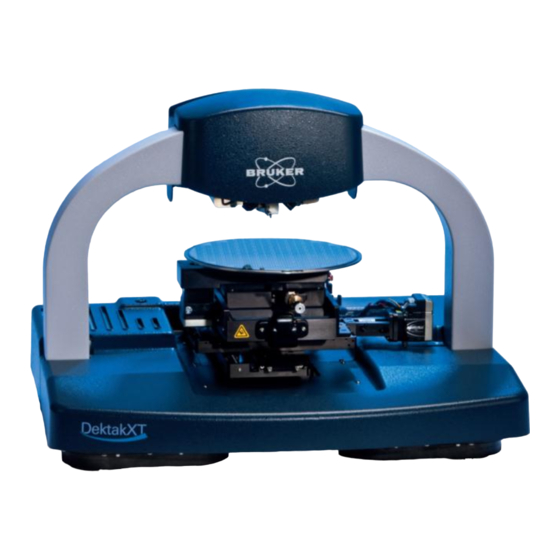
Stylus profiler
Hide thumbs
Also See for DektakXT:
- User manual (83 pages) ,
- Operation manual (8 pages) ,
- Manual (7 pages)
Advertisement
Table of Contents
- 1 Table of Contents
- 2 Safety Precautions
- 3 Unpacking the System
- 4 Installing the Stylus Profiler
- 5 Installing the Computer and Powering up the System
- 6 Installing the Stylus
- 7 Taking a Test Scan Measurement
- 8 Electronically Configuring and Calibrating the Profiler
- 9 General Care and Maintenance
- 10 Declaration of Conformity
- Download this manual
Advertisement
Table of Contents

Related Manuals for Bruker DektakXT


Summary of Contents for Bruker DektakXT
- Page 2 EKTAK TYLUS ROFILER NSTALLATION AND AINTENANCE ANUAL P/N 980-389...
- Page 3 Offenders will be liable for damages. All rights reserved. All configurations and specifications are subject to change without notice. TRADEMARK NOTICE Vision is a registered trademark of Bruker Corporation. All other brand or product names are trademarks or registered trademarks of their respective holders. Bruker Nano Surfaces Business...
-
Page 4: Table Of Contents
ABLE OF ONTENTS Safety Precautions ............1 Unpacking the System . -
Page 6: Safety Precautions
If you purchased one of the vacuum sample fixtures (chucks), you will need a source of vacuum. The DektakXT must sit on a sturdy workbench or vibration 800-873-9750 isolation table. - Page 7 Have an another large table nearby to hold the computer components and DektakXT tool as they are unpacked. The shipping boxes for your DektakXT system appear in the picture that follows. You will have at least two boxes—one for the environmental enclosure and one for the system itself. If you purchased the computer and monitor from Bruker, you also will have one box for each of those items.
- Page 8 This is the box for the Dell computer. After you open the box, you will see two smaller boxes on top of the computer. This first box contains all of the cables, a mouse, documentation, backup CDs, and a shipping list. The smaller box contains the keyboard.
- Page 9 Remove the environmental enclosure and place it on a table near the final location of the DektakXT tool. This is the box that holds the DektakXT stylus profiler. The tool is very heavy, so you will need two people to lift it.
- Page 10 Do a complete inventory of all of the items shown on the checklist before discarding the packing materials. If anything is missing, recheck the boxes. If you have any questions, call 800-873-9750 Bruker Customer Service at...
-
Page 11: Installing The Stylus Profiler
INSTALLING THE PROFILER This section tells you how to install your new DektakXT stylus profiler. Make sure that the tool is sitting on the system’s final location with ample access to both front and back. The environmental enclosure should be sitting on a nearby table. - Page 12 IMPORTANT! Be sure to save all of the shipping straps, brackets, and screws in case you need to ship the tool to another facility in the future. Loosen the orange Velcro shipping strap that is attached to the top of the stage. Then slide it out of the slots in the two red shipping brackets and set it aside.
- Page 13 Place the screw through the plastic cable clamp and back into the stage. Tighten it. You will see two more shipping brackets on the front of the stage. Loosen the screws with a Phillips screw driver, remove the brackets, and re-tighten the screws.
- Page 14 While you are at the back of the tool, attach the cables before removing the other shipping brackets. The connector panel is located on the right side. There are three USB connectors, so find the three USB cables that shipped with the system. Your cables may look slightly different from the ones shown below, but this will not be a problem.
- Page 15 Locate the power supply, a rectangular black box.
- Page 16 Attach the round connector to the power connector on the tool. Take care to rotate the connector properly, so that the key fits. The last cable is the tan-colored one that is attached to the EMO box. Plug it in and then return to the front of the tool.
- Page 17 If you have a wafer sample fixture (chuck), you will need to mount that next. Although yours may not look exactly like this one, it will still mount with three screws. Using the appropriate hex head wrench, attach the sample fixture as shown. You will need to remove the head cover to gain access to the Z axis shipping bracket.
- Page 18 Lift up the right side first; this will be easier. Use the appropriate hex head wrench to remove the two silver screws. Remove the Z-axis shipping bracket. Use a small Phillips screwdriver to remove the two black screws from the bracket.
- Page 19 These two screws must be installed back in the holes in the Z axis bearing, as shown below. Now replace the head cover, lowering the left side first. Place the environmental over the fully assembled DektakXT tool. Make sure that the enclosure does not touch the edges of the DektakXT itself.
-
Page 20: Installing The Computer And Powering Up The System
INSTALLING THE COMPUTER AND POWERING UP THE SYSTEM Remove the software key from inside the Vision64 CD case. Insert the key into one of the USB ports in the back of the computer. - Page 21 Pick up the free ends of the three USB cables. Insert them in the USB ports. Set the keyboard and mouse next to the computer.
- Page 22 Insert these two USB cables in the remaining two ports on the back of the computer. Locate the cable for the monitor. Attach the cable to the connector on the video board in the computer. Be sure to tighten the screws.
- Page 23 Insert one of the power cords into the computer. Insert another power cord into the receptacle in the power supply.
- Page 24 If you rotate the monitor sideways, you will be able to easily access the connectors. Attach the other end of the cable and tighten the screws. Insert the third power cord in the monitor, and then rotate the monitor back to its normal position. If your system includes the air isolation feet, you will find the air line on the right side of the tool.
- Page 25 Plug all three power cords from the DektakXT tool into a power strip or three wall outlets. Turn on the power supply switch. On the EMO box, make sure the emergency red button is released by rotating it slightly clockwise. Then press the white button.
- Page 26 The head on the bridge moves to its upper limit. The system stops with the stylus in the Tower Up position. • The scan stage initializes. The Vision64 Welcome screen appears, followed by the Vision64 Instrument tab, which includes the DektakXT Live Video Display and Measurement Options window, as shown on the next page.
-
Page 27: Installing The Stylus
INSTALLING THE STYLUS The DektakXT system comes with a tool that magnetically holds the stylus. This tool and one or more styli (if ordered) were shipped in the same box that held the DektakXT profiler. The following picture shows the stylus installed on the sensor head of the DektakXT tool. - Page 28 Front of tool Locate the stylus exchange tool that came in the same box as the DektakXT tool. If its green circle is visible, rotate the thumbscrew in either direction to disengage the magnet and replace the green circle with a gray one.
- Page 29 Place the stylus exchange tool underneath the sensor head on the DektakXT profiler. Holding the stylus exchange tool by the sides, align the alignment pins on its top with the outside of the front of the sensor head.
-
Page 30: Taking A Test Scan Measurement
DektakXT User Manual. If you are not satisfied with the results, check the index of the User Manual or consult the DektakXT online Help. If these steps do not solve your problem, contact Bruker Customer Service at 800-873-9750. -
Page 31: Electronically Configuring And Calibrating The Profiler
On the Instrument tab of the Ribbon in Vision64, click one of the following icons to open its associated dialog box. For instructions on making the settings in each dialog box, see the DektakXT User Manual and the DektakXT online Help.
Need help?
Do you have a question about the DektakXT and is the answer not in the manual?
Questions and answers